Tagged: HydraSDR

RTL-SDR Blog Review of the HydraSDR

HydraSDR is a soon to be released software-defined radio based on the same design as the popular Airspy R2 SDR. However, compared to Airspy, HydraSDR claims to have "Enhanced PCB layout and RF front end with superior power/noise filtering, improved temperature dissipation and peak temperature management," as well as various other improvements. HydraSDR also has the distinction of being made in the USA, whereas Airspy is made in China.

Recently, Benjamin Vernoux, creator of HydraSDR and former collaborator on the Airspy R2 project, sent us a review unit of the HydraSDR. This post is a review of the HydraSDR. However, because the HydraSDR is based on the Airspy R2 and competes directly with it, the two units will be heavily compared.

HydraSDR is launching on Digikey.com for US$189 and the Airspy R2 is available from iTead and other distributors for US$169.

Design Review

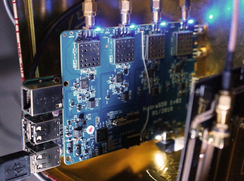
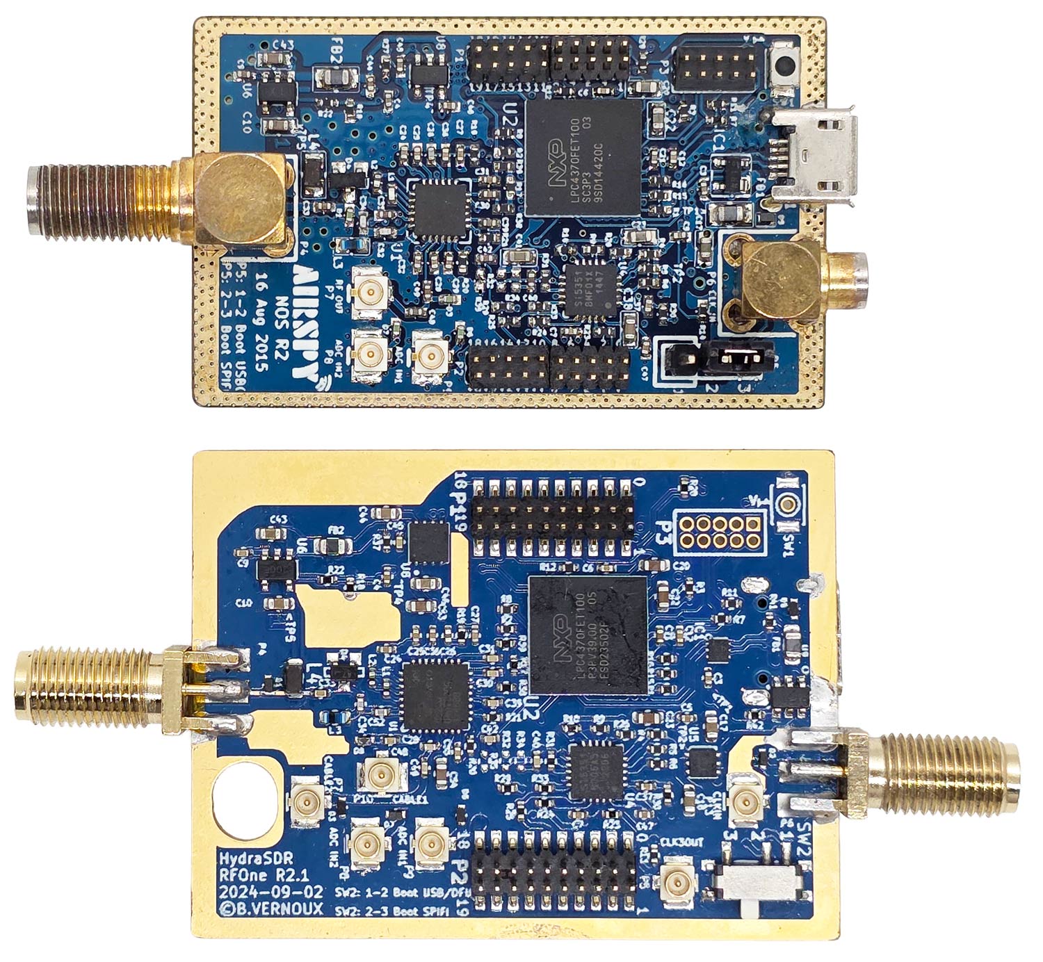
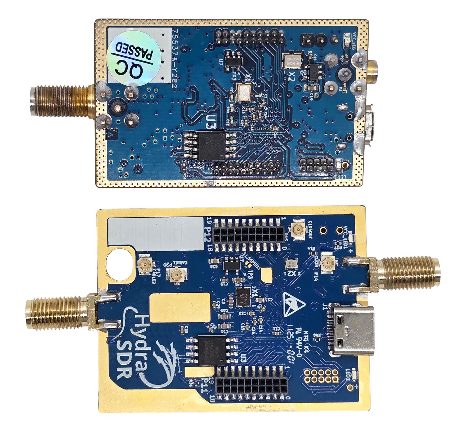
The design of the HydraSDR is very similar to the Airspy R2, which is already known to be a high-performing SDR. Both are based on the LPC4370 microcontroller and its built-in ADC, and they both use similar firmware. The circuit layout, from the top and bottom views, is also almost identical. Benjamin notes that the internal layout has been improved and that several components, such as LDOs, have been upgraded to better ones with reduced noise.

One larger change is that HydraSDR uses a Rafael R828D tuner, instead of the Rafael R860T tuner that the Airspy uses. Both tuners are very similar in terms of operation and performance as they are based on the same design and technology. The R828D has two additional RF input pins; however, on the HydraSDR, they are unused but are routed to two uFL connectors on the bottom of the PCB for advanced users.

Airspy (Top) and HydraSDR (Bottom) PCB Top Side
Airspy (Top) and HydraSDR (Bottom) PCB Bottom Side

Both the HydraSDR and Airspy come in a black anodized aluminum extruded enclosure. The Airspy's enclosure is more compact, but the HydraSDR enclosure is purposely oversized to accommodate up to three HydraSDR PCBs.

However, additional holes for two extra SMA ports and two extra USB-C ports have not been pre-drilled, so we assume the 3x unit may be a separate product coming out in the future. The HydraSDR also utilizes an SMA port for the optional CLK-IN port, unlike the MCX port on the Airspy.

Airspy (Left) and HydraSDR (Right) Side Profile

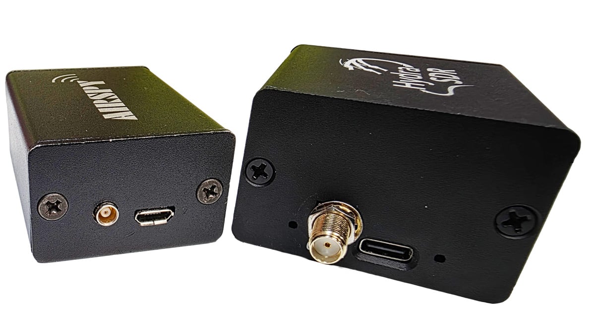
A major win for the HydraSDR is its use of a USB-C connector, whereas the Airspy R2 still uses a micro USB connector. (We note that it is a USB-C connector, but not USB3.0, it is still USB2.0).

The microUSB connector on the Airspy R2 is less robust and can easily disconnect if bumped, even with brand-new cables. The connection on the HydraSDR is rock solid, and no amount of reasonable bumping of the cable can disconnect it.

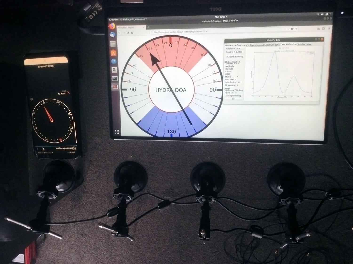
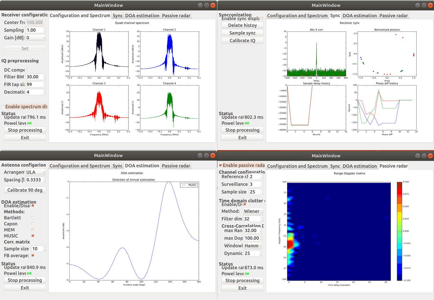
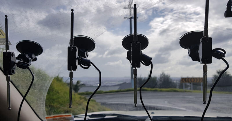
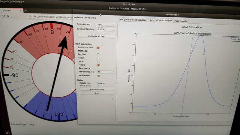
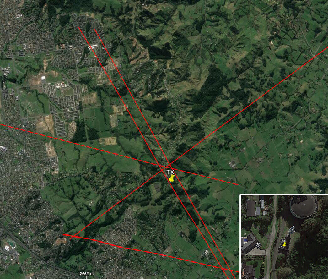
The HydraSDR spec sheet also mentions its suitability for phase-coherent applications, such as radar. However, although you can run all three from the same clock, from what we can see, specialized firmware, software, and external signal and/or noise source hardware would still be required for sample and phase alignment, as the system can not be naturally coherent. We're unsure whether the company will be directly supporting coherent use cases or if coherence is left as an exercise for the customer. 

Software

Both Airspy and HydraSDR use the same USB VID/PID identifiers, so most software should recognize them as the same device.

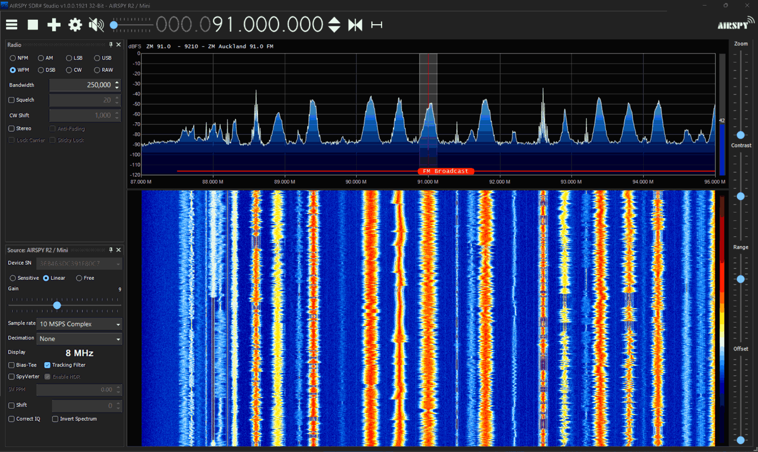
We decided to see if it would run in SDR#, the official software of Airspy. Upon selecting the device as an Airspy R2 in SDR#, we were able to see it work and operate just like a genuine Airspy R2. We want to note that Youssef has mentioned that, in his view, using non-Airspy products like the HydraSDR with the Airspy source would be in violation of SDR# terms, but we will use it in this review for comparison purposes.

HydraSDR Running in SDR# as an Airspy R2 Device

This is interesting because in SDR++, the software recommended by HydraSDR, selecting Airspy R2 as the device results in the device being unable to connect. Currently, SDR++ does not support HydraSDR in its latest releases; however, support is being developed.

For now, until SDR++ officially supports HydraSDR, Benjamin has released a custom fork of SDR++ that will be available on the HydraSDR website.

HydraSDR Running in SDR++ (HydraSDR Fork)

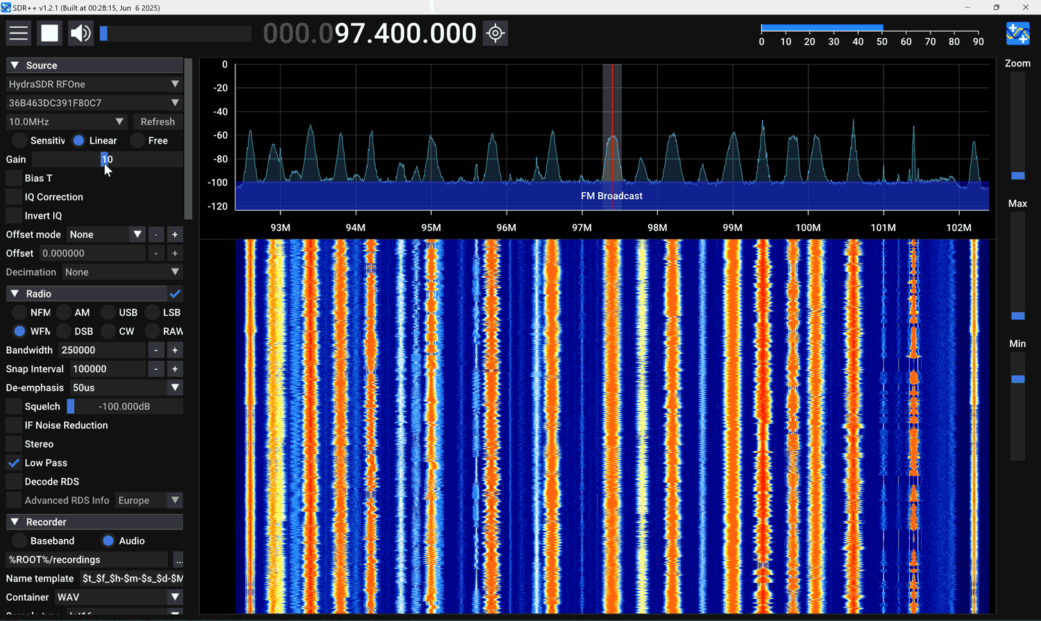
We note a few differences between SDR++ and SDR#. SDR# restricts the visible bandwidth of Airspy devices to 8 MHz, as this hides the edges, which contain aliased signals. SDR++ does not hide the sides. SDR# also has an 'HDR' (high dynamic range) mode for Airspy devices, whereas SDR++ does not. More on HDR mode is discussed under the testing heading. 

When HDR mode was turned OFF, no differences in performance between SDR# and SDR++ were noticed.

We are also aware that HydraSDR is now supported by gr-osmosdr (GNU Radio source block), SatDump (satellite decoding software), and URH (Universal Radio Hacker). 

We also found that HydraSDR runs as an Airspy in SDR-Console V3. Official Airspy software, such as SpyServer and adsb_spy, also work with HydraSDR. We suspect that most software that supports the Airspy will be compatible.

Testing

No Antenna Test

In this test, we connected each SDR to a dummy load and used SDR# to look for signals. If the SDR is shielded well, no signals should be received.

We noticed that the HydraSDR has excellent shielding and is very well protected against signals entering through paths other than the antenna. The Airspy was able to receive a strong TV channel without any antenna, indicating that it has shielding issues.

HydraSDR (Left) Airspy (Right) No Antenna
HydraSDR (Left) Airspy (Right) No Antenna Connected

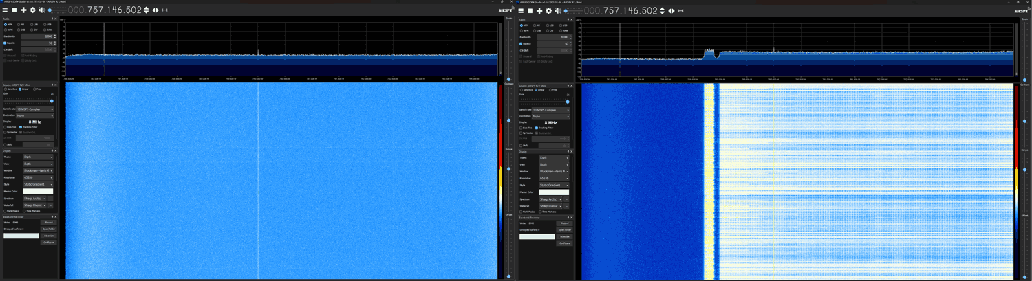
Across the spectrum, the HydraSDR also has a cleaner spectrum with lower power levels on most internal spurs.

Real World SNR Tests

In this test, we received real-world signals with each SDR connected to a roof-mounted Discone, which was in turn connected to a splitter. We increased the gain settings to optimize each SDR for best SNR, which is typically just before it overloads and creates images.

We noticed that the gain distribution on the HydraSDR was slightly different from that of the Airspy, as the HydraSDR would overload on a lower gain setting compared to the Airspy. When optimizing for SNR we found that a gain setting 1-3 notches higher on the Airspy was required.

Once optimized, we found that results were very similar, with a slight 0.5 - 1 dB sensitivity edge going to the HydraSDR; however, this may be within chip-to-chip variances, so we can't say for certain if one is more sensitive than the other.

HydraSDR (Left) Airspy (Right) Same SNR on BCFM in SDR#
HydraSDR (Left), Airspy (Right). Same SNR on BCFM in SDR#
HydraSDR (Left), Airspy (Right). Same SNR on BCFM in SDR++
HydraSDR (Left), Airspy (Right). Slightly better SNR for the HydraSDR at 457 MHz.

Real World Comparison SDR++ vs SDR# 1921

HydraSDR recommends using SDR++, whereas Airspy recommends using the Airspy native software SDR#. While HydraSDR currently works on SDR#, we're not sure if this will continue, as SDR# could possibly block the use of clones and spinoffs. So, it seems fair to compare HydraSDR with SDR++ and Airspy with SDR#.

Under normal operation, with moderate strength signals, both programs appear to give nearly identical performance in terms of audio quality and signal SNR.

However, Youssef has pointed out that SDR# (and SDR-Console) has a special mode called HDR (high dynamic range) available for Airspy products. HDR mode works by optimizing the DSP chain specifically for the Airspy hardware whenever decimation is used. With HDR mode on, we can push the gain setting much higher than we would have otherwise without experiencing overload, resulting in a better SNR.

We are currently aware that only SDR# and SDR-Console V3 implement the Airspy HDR mode tweaks, and SDR++ does not.

Comparing performance between two different programs can be a bit tricky because each uses a slightly different FFT algorithm, resulting in different SNR values being calculated. SDR++ consistently calculates a somewhat higher SNR for the same signal.

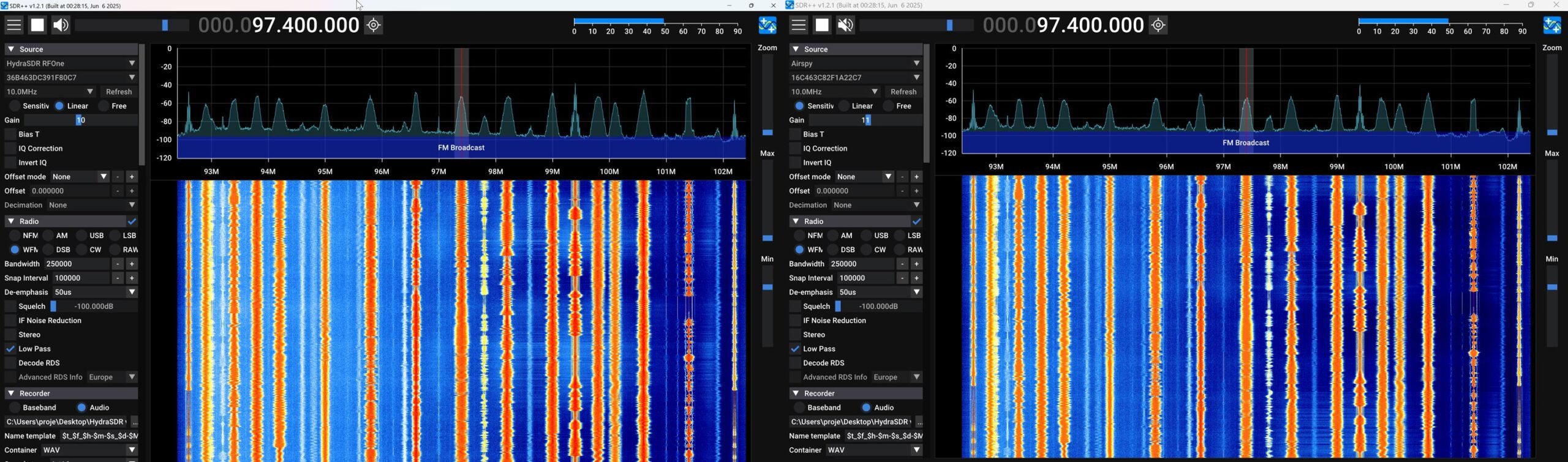
To illustrate the effect of the Airspy HDR mode, we will use two SDR# instances and disable HDR mode for the HydraSDR, simulating the effect of using it in SDR++, which does not have HDR mode. 

HydraSDR with HDR Mode OFF (Left), Airspy (Right) HDR Mode ON

This test showed a rather dramatic +7 dB improvement with HDR mode on. With HDR mode on we were able to increase the gain much further without overload. In the screenshot we increased the gain as far as possible to optimize the SNR on each receiver as much as possible.

For an audio comparison that directly compares Airspy on SDR# vs HydraSDR on SDR++, here is an audio file of the Airspy running SDR# with HDR mode ON, 16x decimation, receiving a weak signal sandwiched between strong signals.

And here is the audio file of SDR++ with 16x decimation receiving the same signal.

Both signals were optimized for the best SNR possible which was just before the SDRs overloaded and displayed intermodulation products. There is a clear difference in audio quality that can be heard, with SDR # emerging as the winner. Note that these HDR improvements may only be seen in a high dynamic range environment (when strong signals are mixed with weak signals) and when decimation is used .

Conclusion

With the Airspy R2 starting to feel a bit dated, the HydraSDR looks to be a great addition to the choice of available SDRs. However, we consider it to be essentially a spinoff of the Airspy with some minor changes made to improve performance and usability. The improved shielding and USB-C port are particularly notable enhancements that we love. Compared against the Airspy, HydraSDR is clearly the better hardware choice.

But if you already have an Airspy R2, there are not enough improvements here to consider the HydraSDR as a next-generation upgrade worth purchasing. That said, if you're looking for a new SDR made in the USA, the HydraSDR should be on your radar.

The Airspy maintains some software advantages, such as official software support and compatibility with SDR#’s and SDR-Consoles HDR mode, which excels in strong signal environments. However, the HydraSDR is directly compatible with the Airspy and currently functions as one in SDR#, allowing it to benefit from HDR mode as well. But this compatibility relies on SDR# not actively blocking it. It's also important to note that Youssef has mentioned that, in his view, using the HyraSDR in SDR# would be in violation of the SDR# licensing agreement, as would loading the HDR enhancements in SDR-Console V3 with HydraSDR (note that we have not verified the legality of this claim).

We also note that Benjamin wants to emphasize that HydraSDR is not designed for use with SDR#, and only SDR++ and other HydraSDR software should be used with it. 

Disclaimer

We have no financial interests in either Airspy or HydraSDR (apart from reselling the YouLoop). The Airspy R2 used in this review was provided to us back in 2015 as a free review unit, and HydraSDR was provided to us recently as a free review unit. Transparency note: Certain parties have claimed that we gave an unfair review to the HydraSDR because they claim that we take referral credit from sales of Airspy units. This is not true. Several years ago, when Airspy was the main recommended upgrade to the RTL-SDR, we briefly trialled a referral program with Airspy, but that program ended many years ago. Any leftover referral links from old blog posts are no longer active. The only Airspy product we sell on our store is the YouLoop antenna, which is unrelated to the SDRs themselves. Some parties have also pointed out that parts of the original review have been removed, and they claim a lack of transparency. In a previous iteration of the review, we mentioned our thoughts and speculation regarding IP law, but removed these sections due to legal threats.

HydraSDR RFOne: A New Upcoming SDR Similar to the Airspy R2

Recently, we have heard news about a new upcoming SDR called the HydraSDR RFOne, created by Benjamin Vernoux, who also worked on the design of the Airspy. The HydraSDR RFOne appears to be very closely based on the Airspy R2 design, and it has very similar specs, including a 24-1800 MHz RX range, 12-bit ADC, and up to 10 MSPS sampling rate output, giving 9 MHz of spectrum.

While HydraSDR is very similar to the Airspy R2 in design, as it uses the same main LPC4370 and the same overall design and layout, there are a few minor changes. The HydraSDR RFOne uses a Rafael R828D tuner chip, instead of the Rafael R820T2 tuner. The R828D has three input pins; however, it appears that only one pin is connected to the SMA input port. The other two ports are connected to uFL connectors on the PCB, which are inaccessible from the metal enclosure.

A second interesting feature is that it comes with a much larger enclosure that can house up to three HydraSDR boards in one. Also, a USB-C connector is used instead of the microUSB (we note that the device would still be USB2.0, not USB3.0).

Another differentiating point is that HydraSDR will be made in the USA, versus China, where the Airspy R2 is made. This may be good for US customers now that the Trump-China tariffs have been implemented. But we have recently seen that iTead, Airspy's Chinese manufacturing partner, recently opened a US store with US stock. So it seems that the retail price of the Airspy will not appear to be affected by tariffs.

HydraSDR with a Single Board
HydraSDR with a Three Boards

You can find more information about the HydraSDR at https://hydrasdr.com. This is still a 'coming soon' landing page; however, if you enter your email, you will be sent a PDF file with the full spec sheet and multiple photos. Pricing for the HydraSDR does not yet appear to have been released.

Over on X, a few early reviewers have already received samples, as we can see some early tests in these posts.

HydraSDR Pinout
HydraSDR Pinout

KerberosSDR Preview: A 4x Coherent RTL-SDR for Direction Finding, Passive Radar and more

KerberosSDR is now available for pre-order over on Indiegogo!

Over the last few months we've been working on a 4-input coherent RTL-SDR called 'KerberosSDR' (formerly known as HydraSDR) that is designed to be a low cost way to get into applications such as RF direction finding, passive radar, beam forming and more. It can also be used as a standard 4-channel SDR for monitoring multiple frequencies as well.

Phase coherent RTL-SDRs have been worked on and demonstrated several times over the past few years, but we've been disappointed to find that so far there hasn't been any easy way to replicate these experiments. The required hardware has been difficult to build and access, and the software has been kept as unreleased closed source or has been too complicated to install and use. With KerberosSDR we aim to change that by making phase coherent applications easier to access and run by providing ready to use hardware and software.

Thanks to our developer Tamás Peto, a PhD student at Budapest University of Technology and Economics whom we hired via the ad in our previous post, and the Othernet (formerly Outernet) engineering team who are our partners on this project, we've been able to build a working system, and demonstrate coherent direction finding and passive radar working as expected (demo videos below). We plan to eventually release Tamás' code as open source so that the entire community can benefit and build on it. Also if KerberosSDR turns a profit, we plan to reinvest some of the profits into continually improving the software and expanding the list of use cases.

KerberosSDR will be usable for coherent applications from ~80-100 MHz up to 1.7 GHz (as a standard receiver it will work down to 24 MHz like a regular RTL-SDR). The lower coherent limitation is due to the phase calibration board, and could be improved by custom creating a larger calibration PCB.

At the moment we are finalizing our prototype, and plan to begin final production within the next 2-3 months.

If you have any interest in KerberosSDR, please sign up to our Kerberos mailing list

Subscribe to our KerberosSDR Announcement

Please select all the ways you would like to hear from RTL-SDR Blog:

You can unsubscribe at any time by clicking the link in the footer of our emails. We use MailChimp as our marketing platform. By clicking below to subscribe, you acknowledge that your information will be transferred to MailChimp for processing. Learn more about MailChimp's privacy practices here.

Direction Finding

KerberosSDR can be used to find the bearing towards a signal using it's coherent direction finding capabilities. The software by Tamás currently implements several direction finding algorithms such as Bartlett, Capon, Maximum Entropy (MEM) and MUSIC. In the video below we show a quick test of the direction finding system working with a HackRF being used as a signal source, and four dipole antennas connected to KerberosSDR in a linear array. The MUSIC algorithm is used.

KerberosSDR Direction Finding Test

In the image below we also attempted to find the direction towards a known TETRA transmitter. We were able to confirm the direction with an Android compass app that points towards the known transmitter location. As the two angles match, we can be confident that Kerberos is finding the correct direction to the transmitter.

Finding the direction of a TETRA Transmitter

Passive Radar

KerberosSDR can also be used for passive radar. Normal radar systems work by transmitting a pulse of RF energy, and listening to the reflections from objects like planes, cars and ships. Passive radar works by using already existing transmitters such as those for FM/TV and listening for reflections that bounce of objects.

With a simple passive radar system you need two directional antennas and two coherent receivers. One antenna points at the transmitting 'reference' tower, and the other at the 'surveillance' area where you want to listen for reflections. It's important to try and keep as much of the reference signal out of the surveillance antenna as possible, which is why directional antennas like Yagi's are used.

The result is a doppler vs time delay graph, where the reflection of aircraft, cars, ships and other objects can be seen. The doppler gives you the speed of the object relative to your antenna and the transmitting tower, and the time delay gives you the distance relative to your antenna and the transmitter tower.

Below is an example time lapse video of KerberosSDR being used for passive radar. The reference antenna points towards a DVB-T transmitter at 588 MHz, and the surveillance antenna overlooks a small neighborhood, with aircraft sometimes flying over. The antennas we used were two very cheap TV Yagis.

You can constantly see the reflections from vehicles at small doppler values (low speeds), and every now and then you see an aircraft reflection which shows up at much higher doppler (speed) and further time delay (distance) points. 

More information about KerberosSDR

KerberosSDR includes:

  • 4x Coherent R820T2 based RTL-SDR dongles with standard 24 MHz - 1.7 GHz frequency range
  • On board GPIO switched wide band noise source for sample sync and phase calibration
  • Special phase calibration PCB for 4x inputs. Required to make the Kerberos phase coherent.
  • On board USB Hub, so only one USB port is required on the PC
  • Shielded metal enclosure

KerberosSDR can also be extended to 8x receivers by daisy chaining two boards together, so that their clocks and noise sources are connected. We've also taken into account undesirable effects such as heat related PLL drift which can be an issue for phase coherence.

At the moment we are also investigating whether singleboard computers like the Raspberry Pi 3 or Tinkerboard can be used, and there will be a header available for powering them via the Kerberos PCB. In the future we also plan to work on optimizing the code and potentially using CUDA/OpenCL GPU optimizations for passive radar so everything runs smoothly.

Once released we plan to have extensive tutorials and documentation that show exactly how to set up and replicate direction finding and passive radar experiments with low cost antennas.

Screenshots of KerberosSDR software:

Screenshots of each KerberosSDR software screen

Remember, if you're interested please sign up to the KerberosSDR mailing list for announcements and the chance to get in early with the cheaper first 100 units.

Be on the look out for more interesting demos that will be posted in the coming weeks!

[the_ad id="14114"]

Update: Please note that due to a Trademark complaint, we have changed the name of this unit from HydraSDR to KerberosSDR.

KerberosSDR Updates: 27 August 18

This week we've managed to get the KerberosSDR demo software made by Tamás Peto functioning on a TinkerBoard. The TinkerBoard is a US$60 single board computer. It's similar to a Raspberry Pi 3, but more powerful. We've also tested the app running on the Raspberry Pi 3 and Odroid XU4. The Pi 3 is capable of running the software but it is a little slow, and the Odroid XU4 is a little faster than the TinkerBoard. In the future we hope to further optimize the code so even Raspberry Pi 3's will be smooth.

In the video below we used a circular array of four whip antennas connected to KerberosSDR. The TinkerBoard is connected to KerberosSDR and is set up to generate a WiFi hotspot, which we connect to with an Android phone and a Windows laptop. The Windows laptop connects to the TinkerBoard's desktop via VNC, and the Android phone receives an HTML/JavaScript based compass display via an Apache server running on the Tinkerboard. With this setup we can wirelessly control and view information from KerberosSDR and the TinkerBoard.

We've also tested the KerberosSDR system on a real signal, and have found it to work as expected. More demo's of that coming later.

For more info on KerberosSDR please see our previous announcement post.

KerberosSDR Direction Finding Test 2: Tinkerboard + Circular Array

KerberosSDR Prototype
KerberosSDR Prototype with TinkerBoard Running Computations

KerberosSDR Updates: 4 September 2018

In this post we'll show an experiment that we performed which was to pinpoint the location of a transmitter using KerberosSDR's coherent direction finding capabilities. RF direction finding is the art of using equipment to determine the location of a transmitting signal. The simplest way is by using a directional antenna like a Yagi to try and determine the bearing based on signal strength. Another method is using a pseudo-doppler or coherent array of antennas to determine a bearing based on phase information.

For the test we tuned the KerberosSDR RTL-SDRs to listen to a signal at 858 MHz and then drove to multiple locations to take direction readings. The antennas were set up as a linear array of four dipole antennas mounted on the windshield of a car. To save space, the dipoles were spaced at approximately a 1/3 the frequency wavelength, but we note that optimal spacing is at half a wavelength. The four dipole antennas were connected to KerberosSDR, with a laptop running the direction finding demo software. 

Low cost direction finding array mounted to vehicle windshield.

Our open source demo software (to be released later when KerberosSDR ships) developed by Tamás Peto gives us a graph and compass display that shows the measured bearing towards the transmitter location. The measured bearing is relative to the antenna array, so we simply convert it by taking the difference between the car's bearing (determined approximately via road direction and landmarks in Google Earth) and the measured bearing. This hopefully results in a line crossing near to the transmitter. Multiple readings taken at different locations will end up intersecting, and where the intersection occurs is near to where the transmitter should be. 

KerberoSDR SDR Directing Finding DOA Reading

In the image below you can see the five bearing measurements that we made with KerberosSDR. Four lines converge to the vicinity of the transmitter, and one diverges. The divergent reading can be explained by multipath. In that location the direct path to the transmitter was blocked by a large house and trees, so it probably detected the signal as coming in from the direction of a reflection. But regardless with four good readings it was possible to pinpoint the transmitting tower to within 400 meters.

In the future we hope to be able to automate this process by using GPS and/or e-compass data to automatically draw bearings on a map as the car moves around. The readings could also be combined with signal strength heatmap data for improved accuracy.

This sort of capability could be useful for finding the transmit location of a mystery signal, locating a lost beacon, locating pirate or interfering transmitters, determining a source of noise and more.

KerberosSDR pinpointing a transmitters location

KerberosSDR Updates 7 September 2018

For this test we parked our car to the side of a highway and pointed a cheap DVB-T Yagi antenna towards a DVB-T transmission tower, and another cheap Yagi down the road. The video shown below displays the results captured over a 5 minute period. The blips on the top half of the display indicate vehicles closing on our location (positive doppler shift), and the blips on the bottom half indicate objects moving away (negative doppler shift). 

DVB-T Antennas In Car

The resolution of each individual vehicle is not great, but it is sufficient to see the overall speed of the highway and could be used to determine if a road is experiencing traffic slowdowns or not. When larger vehicles pass by it is also obvious on the display by the brighter blip that they show. The display also shows us that the highway direction coming towards us is much busier than the direction moving away.

In the future we'll be working on optimizing the code so that the display updates much faster and smoother. It may also be possible in the future to use the third and fourth tuners to obtain even greater object resolution.

KerberosSDR Updates 27 September 2018

In this post we're showing some more passive radar demos. The first video is a time lapse of aircraft coming in to land at a nearby airport. The setup consists of two DVB-T Yagi antennas, with KerberosSDR tuned to a DVB-T signal at 584 MHz. The reference antenna points towards a TV tower to the west, and the surveillance antenna points south. Two highlighted lines indicate roughly where reflections can be seen from within the beam width (not taking into account blockages from mountains, trees etc).

The second video shows a short time lapse of a circling helicopter captured by the passive radar. The helicopter did not show up on ADS-B. On the left are reflections from cars and in the middle you can see the helicopter's reflection moving around.

We are expecting to receive the final prototype of KerberosSDR within the next few weeks. If all is well we may begin taking pre-orders shortly after confirming the prototype.