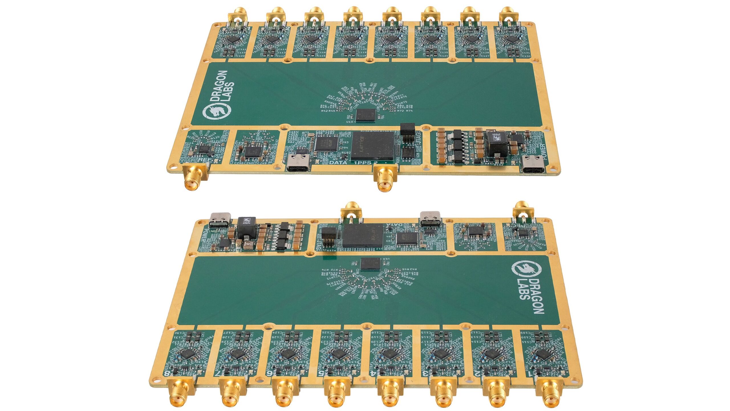
Dragon Labs have recently announced that the CR-8 model is getting ready for crowdfunding on CrowdSupply. The CR-8 is an 8-channel coherent software-defined radio with a 12-bit ADC, a tuning range of 25 MHz to 1750 MHz, and 8 MHz of bandwidth per channel. A coherent SDR unlocks various applications such as radio direction finding, beamforming, and antenna diversity.
The CR-8 was originally designed for a Master's thesis by Alexandre Rouma, who is also the creator of the popular SDR++ software, which is commonly used by RTL-SDR enthusiasts.
The core of the build appears to consist of R860 tuners for each channel and an MCP3721-200 analog-to-digital converter (ADC). The MCP3721-200 is a chip commonly used for radar, imaging, and cellular base station applications, as it naturally provides aligned samples with built-in fractional delay recovery, making it ideal for coherent applications. A seperate signal source on the PCB provides the needed signal for the phase calibration of the tuners.
SDR++ and SatDump will natively support the CR-8, and there is also a GNU Radio source block. While the C API is open source, they note that the firmware will be closed source.
Pricing has yet to be announced, but we found a recent comment from the team indicating a target price of US$500 - $600 for the bare PCB, with a CNC-milled enclosure available as an optional add-on.
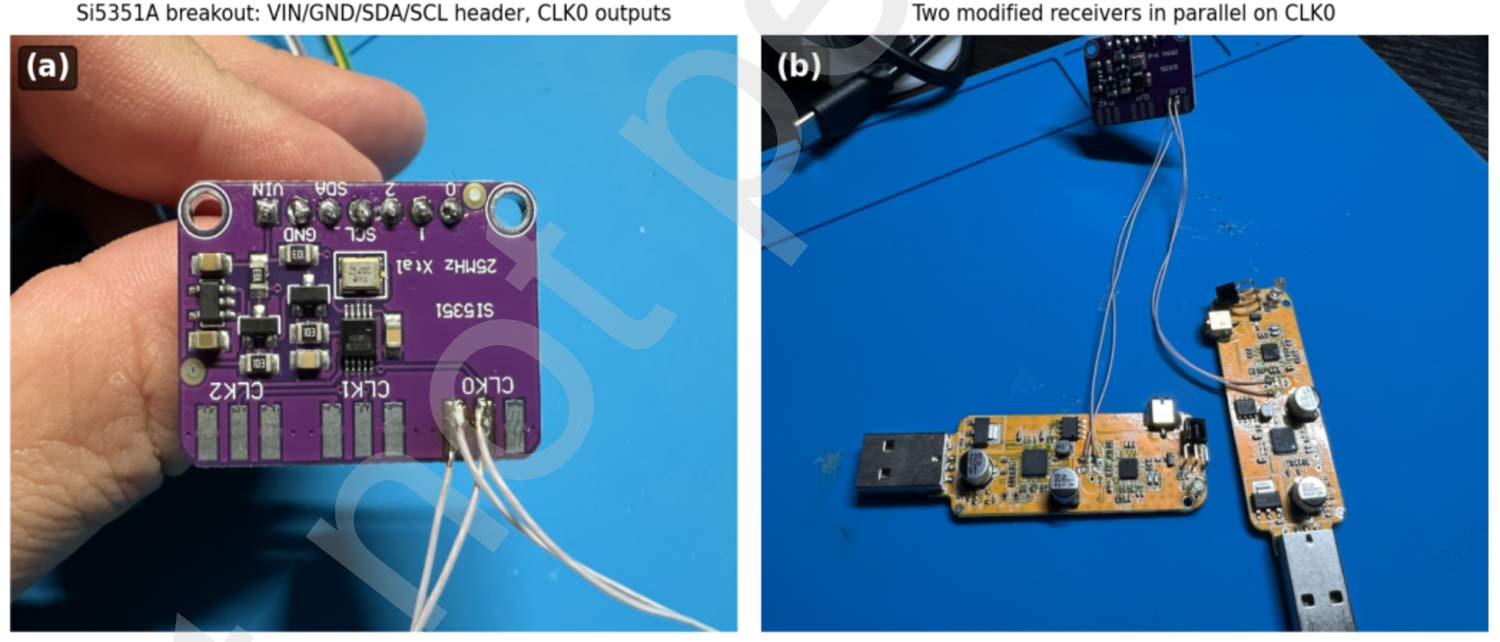
Modifying RTL-SDR dongles to run from the same clock source to create a phase-coherent receiver is something that has been done for many years. The original experiments from 2015 by Tatu Peltola and others are what inspired the creation of the KerberosSDR and KrakenSDR coherent RTL-SDR radio systems for radio direction finding.
Recently, Mykhailo Shumilov, an independent researcher in Ukraine, wrote a paperon running RTL-SDR dongles from the same clock, which may be of interest to those working on coherence experiments. In his experiments, he uses an Si5351A as the reference clock and two RTL-SDR dongles. While his paper doesn't cover any new ground, he presents concrete measurements confirming the phase coherence-stabilizing effect of running two RTL-SDR dongles from the same clock.
AI-Disclaimer: The paper author notes that AI was used to aid in the writing of the paper.
Running two RTL-SDR dongles from a shared clock for phase coherence
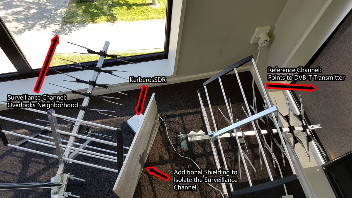
KerberosSDR is our four tuner coherent RTL-SDR product made in collaboration with Othernet. With KerberosSDR applications like radio direction finding and passive radar are possible, and our free open source demo software helps to make it easier to get started exploring these applications. In this post we explore how a simple passive radar setup can be used to measure how busy a neighborhood is in terms of vehicular traffic.
Passive radar makes use of already existing strong 'illuminator' signals such as broadcast FM, DAB, digital TV and cellular. When these signals reflect off a moving metallic object like an aircraft or vehicle, it distorts the signal slightly. By comparing the distorted signal to a clean signal we can determine the distance and speed of the object causing the reflection. Wide reaching digital signals like DVB-T and DAB are often the best illuminators to use. Wideband cellular signals can also be used to detect more local targets.
In a simple passive radar system we use two directional antennas such as Yagi's. One Yagi points towards the broadcast tower and receives the clean non-distorted reference signal. This is known as the reference channel. A second Yagi points towards the area you'd like to monitor for reflections, and this is called the surveillance channel.
In our setup we point the reference channel Yagi towards a 601 MHz DVB-T transmitter roughly 33 km away. A second Yagi is placed on a vantage point overlooking a neighborhood. The Yagi's used are cheap DVB-T TV Yagi's that can be found in any electronics or TV retail store (or on Amazon for ~$30 - $60 USD). In the software we used a bandwidth of 2.4 MHz and adjusted the gains for maximum SNR.
It is important that the surveillance channel is isolated from the reference signal as much as possible. We improve the isolation simply by placing a metal sheet next to the surveillance Yagi to block the reference DVB-T signal more. Note that putting the antennas outside will obviously result in much better results. These walls and windows contain metal which significantly reduce signal strength. We also added our RTL-SDR Blog wideband LNA to the surveillance channel powered by a cheap external bias tee to improve the noise figure of the surveillance channel.
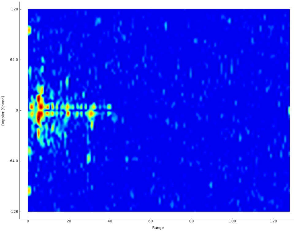
The resulting passive radar display shows us a live view of objects reflecting. Each dot on the display represents a moving vehicle that is reflecting the DVB-T surveillance signal. In the image shown below the multiple colored objects in the left center are vehicles. The X-Axis shows the distance to the object, and the Y-Axis shows the doppler speed. Both axes are relative to the observation location AND the transmit tower location.
Vehicles on the Passive Radar Display
When there are more moving cars on the road during the day and rush hours, there are more blips seen on the passive radar display. Larger vehicles also produce larger and stronger blips. By simply summing the matrix that produces this 2D display, we can get a crude measurement of how busy the neighborhood is, in terms of cars on the road since reflections are represented by higher values in the matrix. We logged this busyness value over the course of a day and plotted it on a graph.
The resulting graph is as you'd intuitively expect. At 6AM we start to see an increase in vehicles with people beginning their commute to work. This peaks at around 8:30AM - 9am with parents presumably dropping their kids off to the neighborhood school which starts classes at 9AM. From there busyness is relatively stable throughout the day. Busyness begins to drop right down again at 7PM when most people are home from work, and reaches it's minimum at around 3am.
Traffic Busyness detected with KerberosSDR Passive Radar
One limitation is that this system cannot detect vehicles that are not moving (i.e. stuck in standstill traffic). Since the doppler speed return will be zero, resulting in no ping on the radar display. The detection of ground traffic can also be distorted by aircraft flying nearby. Aircraft detections result in strong blips on the radar display which can give a false traffic result.
It would also be possible to further break down the data. We could determine the overall direction of traffic flow by looking at the positive and negative doppler shifts, and also break down busyness by distance and determine which distances correspond to particular roads. In the future we hope to be able to use the additional channels on the KerberosSDR to combine passive radar and direction finding, so that the the blips can actually be directly plotted on a map.
If you want to try something similar on the KerberosSDR software edit the RD_plot function in the _GUI/hydra_main_window.py file, and add the following simple code before CAFMatrix is normalized. You'll then get a log file traffic.txt which can be plotted in excel (remember to convert Unix time to real time and apply a moving average)
SDRPlay have recently published a video demonstrating how the new RSPduo diversity feature in SDRUno can be used to cancel local interference. The SDRplay RSPDuo is a 14-bit dual tuner software defined radio capable of tuning between 1 kHz - 2 GHz. It's defining feature is that it has two receivers in one radio, which should allow for interesting phase coherent applications such as diversity. The RSPDuo's diversity feature allows us to either combine two antenna signals together for an up to 3 dB increase, or for removal of an unwanted noise source via subtraction of signals.
In the video they show a broadcast AM signal that has it's SNR reduced by being on top of a local electrical noise source. The use a Bonito Mega-dipole on tuner 1, and a Bonito Mini-whip on tuner 2. The Mini-whip appears to receive the local interference stronger, so can be subtracted away from the Mega-dipole's signal with the diversity function. The result is improved SNR, and the noise is almost entirely cancelled.
There are 2 very practical applications for diversity software. The first is MRC (Maximum Ratio Combination) Diversity which, in order to be effective, needs two antennas presenting the same signal with some degree of diversity. Then there is this second impressive application which is becoming more and more useful due to the growing number of domestic sources of interference.
This is possible in an RSPduo, due to the coherent nature of the combined tuner streams being presented to the computer for processing.
Using Diversity in SDRplay's SDRuno to Cancel Local Interference
As promised we announced the release to KerberosSDR mailing list subscribers first, so that they'd be the first to get the initial discounted early bird units. However due to much higher than expected interest, we have released a few "second early bird" units at a still discounted price of $115 + shipping. We're only going to release 300 of these so get in quick before the price jumps up to $125. Our pre-order campaign will last 30 days, and afterwards the retail price will become $150.
If you weren't already aware, over the past few months we've been working with the engineering team at Othernet.is to create a 4x Coherent RTL-SDR that we're calling KerberosSDR. A coherent RTL-SDR allows you to perform interesting experiments such as RF direction finding, passive radar and beam forming. In conjunction with developer Tamas Peto, we have also had developed open source demo software for the board, which allows you to test direction finding and passive radar. The open source software also provides a good DSP base for extension.
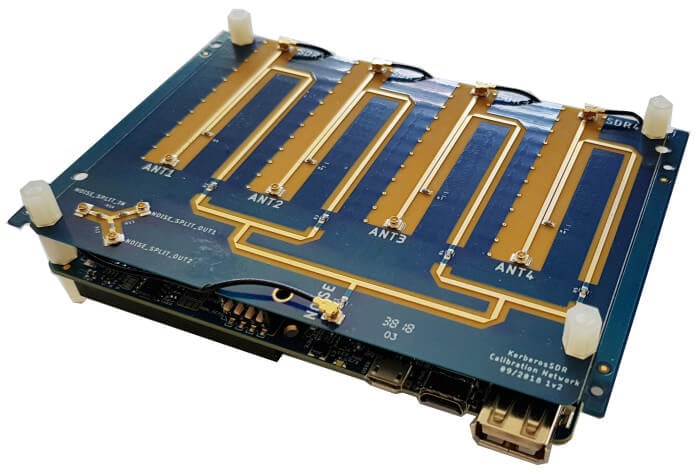
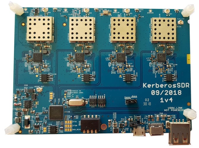
KerberosSDR with Calibration Board Attached (Metal Enclosure with SMA connectors Not Shown)KerberosSDR Main Board (Metal Enclosure with SMA connectors Not Shown)
KerberosSDR is our upcoming low cost 4-tuner coherent RTL-SDR. With four antenna inputs it can be used as a standard array of four individual RTL-SDRs, or in coherent applications such as direction finding, passive radar and beam forming. More information can be found on the KerberosSDR main post. Please remember to sign up to our KerberosSDR mailing list on the main post or at the end of this post, as subscribers will receive a discount coupon valid for the first 100 pre-order sales. The list also helps us determine interest levels and how many units to produce.
In this post we're showing some more passive radar demos. The first video is a time lapse of aircraft coming in to land at a nearby airport. The setup consists of two DVB-T Yagi antennas, with KerberosSDR tuned to a DVB-T signal at 584 MHz. The reference antenna points towards a TV tower to the west, and the surveillance antenna points south. Two highlighted lines indicate roughly where reflections can be seen from within the beam width (not taking into account blockages from mountains, trees etc).
The second video shows a short time lapse of a circling helicopter captured by the passive radar. The helicopter did not show up on ADS-B. On the left are reflections from cars and in the middle you can see the helicopter's reflection moving around.
We are expecting to receive the final prototype of KerberosSDR within the next few weeks. If all is well we may begin taking pre-orders shortly after confirming the prototype.
KerberosSDR is our upcoming low cost 4-tuner coherent RTL-SDR. With four antenna inputs it can be used as a standard array of four individual RTL-SDRs, or in coherent applications such as direction finding, passive radar and beam forming. More information can be found on the KerberosSDR main post. Please remember to sign up to our KerberosSDR mailing list on the main post or at the end of this post, as subscribers will receive a discount coupon valid for the first 100 pre-order sales. The list also helps us determine interest levels and how many units to produce.
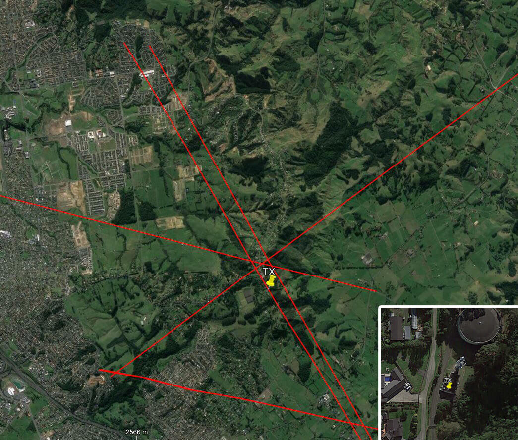
In this post we'll show an experiment that we performed which was to pinpoint the location of a transmitter using KerberosSDR's coherent direction finding capabilities. RF direction finding is the art of using equipment to determine the location of a transmitting signal. The simplest way is by using a directional antenna like a Yagi to try and determine the bearing based on signal strength. Another method is using a pseudo-doppler or coherent array of antennas to determine a bearing based on phase information.
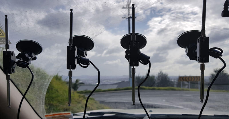
For the test we tuned the KerberosSDR RTL-SDRs to listen to a signal at 858 MHz and then drove to multiple locations to take direction readings. The antennas were set up as a linear array of four dipole antennas mounted on the windshield of a car. To save space, the dipoles were spaced at approximately a 1/3 the frequency wavelength, but we note that optimal spacing is at half a wavelength. The four dipole antennas were connected to KerberosSDR, with a laptop running the direction finding demo software.
Low cost direction finding array mounted to vehicle windshield.
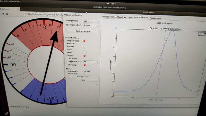
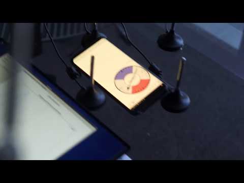
Our open source demo software (to be released later when KerberosSDR ships) developed by Tamás Peto gives us a graph and compass display that shows the measured bearing towards the transmitter location. The measured bearing is relative to the antenna array, so we simply convert it by taking the difference between the car's bearing (determined approximately via road direction and landmarks in Google Earth) and the measured bearing. This hopefully results in a line crossing near to the transmitter. Multiple readings taken at different locations will end up intersecting, and where the intersection occurs is near to where the transmitter should be.
KerberoSDR SDR Directing Finding DOA Reading
In the image below you can see the five bearing measurements that we made with KerberosSDR. Four lines converge to the vicinity of the transmitter, and one diverges. The divergent reading can be explained by multipath. In that location the direct path to the transmitter was blocked by a large house and trees, so it probably detected the signal as coming in from the direction of a reflection. But regardless with four good readings it was possible to pinpoint the transmitting tower to within 400 meters.
In the future we hope to be able to automate this process by using GPS and/or e-compass data to automatically draw bearings on a map as the car moves around. The readings could also be combined with signal strength heatmap data for improved accuracy.
This sort of capability could be useful for finding the transmit location of a mystery signal, locating a lost beacon, locating pirate or interfering transmitters, determining a source of noise, for use during fox hunts and more.
KerberosSDR pinpointing a transmitters locationKerberosSDR Prototype
KerberosSDR (formerly HydraSDR) is our upcoming 4-input coherent RTL-SDR. It's designed for coherent applications like RF direction finding, passive radar, beam forming and more, but can also be used as a standard 4-channel SDR for monitoring multiple frequencies. In this post we demonstrate the direction finding application running on the TinkerBoard.
Reminder: If you have any interest in KerberosSDR, please sign up to our KerberosSDR mailing list. Subscribers to this list will be the first to know when KerberosSDR goes on preorder, and the first 100 sales will receive a discounted price.
KerberosSDR Updates
This week we've managed to get the KerberosSDR demo software made by Tamás Peto functioning on a TinkerBoard. The TinkerBoard is a US$60 single board computer. It's similar to a Raspberry Pi 3, but more powerful. We've also tested the app running on the Raspberry Pi 3 and Odroid XU4. The Pi 3 is capable of running the software but it is a little slow, and the Odroid XU4 is a little faster than the TinkerBoard. In the future we hope to further optimize the code so even Raspberry Pi 3's will be smooth.
In the video below we used a circular array of four whip antennas connected to KerberosSDR. The TinkerBoard is connected to KerberosSDR and is set up to generate a WiFi hotspot, which we connect to with an Android phone and a Windows laptop. The Windows laptop connects to the TinkerBoard's desktop via VNC, and the Android phone receives an HTML/JavaScript based compass display via an Apache server running on the Tinkerboard. With this setup we can wirelessly control and view information from KerberosSDR and the TinkerBoard.
We've also tested the KerberosSDR system on a real signal, and have found it to work as expected. More demo's of that coming later.