Tutorial: Setting up a Low Cost QRP (FT8, JT9, WSPR etc) Monitoring Station with an RTL-SDR V3 and Raspberry Pi 3
QRP is amateur radio slang for 'low transmit power'. QRP digital modes such as FT8, JT9, JT65 and WSPR are modes designed to be transmit and received across the world on low transmit powers (although not everyone uses only low power). The special design of these modes allows even weak signals to be decodable by the receiving software. Released in 2017, FT8 has shown itself to now be the most popular mode by far with JT9 and JT65 taking a backseat. WSPR is also not as active as FT8, although WSPR is more of a beacon mode rather one used for making contacts.
Apart from being used by hams to make contacts, these weak signal modes are also valuable indicators of the current HF propagation conditions. Each packet contains information on the location of the transmitter, so you can see where and how far away the packet you've received comes from. You also don't need to be a ham to set up a monitoring station. As an SWL (shortwave listener), it can be quite interesting to simply see how far away you can receive from, and how many countries in the world you can 'collect' signals from.
This tutorial is inspired by dg0opk's videos and blog post on monitoring QRP with single board computers. We'll show you how to set up a super cheap QRP monitoring station using an RTL-SDR V3 and a Raspberry Pi 3. The total cost should be about US $56 ($21 for the RTL-SDR V3, and $35 for the Pi 3).
With this setup you'll be able to continuously monitor multiple modes within the same band simultaneously (e.g. monitor 20 meter FT8, JT65+JT9 and WSPR all on one dongle at the same time). The method for creating multiple channels in Linux may also be useful for other applications. If you happen to have an upconverter or a better SDR to dedicate to monitoring such as an SDRplay or an Airspy HF+, then this can substitute for the RTL-SDR V3 as well. The parts you'll need are as follows:
- RTL-SDR V3 (or upconverter, or other HF & Linux capable SDR)
- Raspberry Pi 3 (or other SBC with similar performance)
- Internet connection
- Band filter (optional but recommended)
- HF antenna (this could be as simple as a long wire)
Examples of QRP Receivers with an RTL-SDR
One week of #FT8 monitoring with the @rtlsdrblog V3 dongle using direct sampling on 30m with a 90ft longwire. 3151 unique calls, 2836 grids and 86 countries. ADIF from #pskreporter and mapped with @GridTracker . pic.twitter.com/1c826gDoce
— Johnny (@cuoops) June 15, 2018

Setting up the Raspberry Pi 3
In this tutorial we use a Raspberry Pi 3, but any SBC (single board computer) with similar or better performance could probably be substituted. Here we'll first set up the Pi for remote desktop connections via RealVNC.
- First as usual for any Pi installation, burn a fresh copy of Raspbian Stretch (or newer if reading in the future) to an SD card, insert the SD card into the Pi, plug in a keyboard and mouse, HDMI monitor and power.
- Once you get to the desktop open a terminal and type in "sudo raspi-config". Here in the localisation settings change the timezone to UTC (localisation options -> time zones -> none of the above -> UTC), set up the keyboard for your locale, and enable VNC.
- In raspi-config also enable VNC under Interfacing Options.
- Using the Raspberry Pi RealVNC setup instructions, set up a RealVNC Viewer account, or if connecting over the local network, just write down your Pi's local IP by using "ifconfig" at the terminal. Note that after enabling VNC in the previous step you can access the RealVNC server settings to login in the top right of the Raspberry Pi taskbar.
- At this point if you like you can remove the HDMI monitor and connect to the Pi over VNC.
Installing Software
Install the following software on your Pi 3.
RTL-SDR Drivers
First we'll install the RTL-SDR drivers. We require the Keenerd drivers for the V3, as these are the only drivers that allow us to run the rtl_sdr software in direct sampling Q-branch mode, which is required for HF reception on the RTL-SDR V3.
sudo apt-get update
sudo apt-get install libusb-1.0-0-dev git cmake -y
git clone https://github.com/keenerd/rtl-sdr
cd rtl-sdr/
mkdir build
cd build
cmake ../ -DINSTALL_UDEV_RULES=ON
make
sudo make install
sudo cp ../rtl-sdr.rules /etc/udev/rules.d/
sudo ldconfig

echo 'blacklist dvb_usb_rtl28xxu' | sudo tee --append /etc/modprobe.d/blacklist-dvb_usb_rtl28xxu.conf
Now reboot to apply the blacklist, and plug in your RTL-SDR.
PulseAudio & MPlayer
We'll need PulseAudio to create virtual audio cables and we'll also install mplayer for playing the audio.
sudo apt-get install pulseaudio pavucontrol mplayer -y
CSDR
CSDR is a library of DSP functions that we'll use to set up a multi-channel receiver.
sudo apt-get install libfftw3-dev -y

cd ~
git clone https://github.com/simonyiszk/csdr
cd csdr
Before going any further, for the Pi 3 we recommend editing the Makefile and changing the PARAMS_NEON flags to the following. The Makefile can be opened with "sudo leafpad Makefile"
-march=armv8-a
-mtune=cortex-a53
-mfpu=neon-fp-armv8.
Also under PARAMS_RASPI set:
-mcpu=cortex-a53
-mfpu=neon-fp-armv8.
We're not sure if it actually does anything, but the idea is that this should help optimize the code for the Pi 3 CPU. For any other SBC, you'll want to check what these settings should be for your architecture.
Close and save the file, then run:
make
sudo make install
ncat
ncat is a TCP server that we'll use to help us set up a multi channel receiver.
sudo apt-get install nmap -y
Chrony
We'll use Chrony to adjust the time offset required by these QRP modes. Configuration will be discussed later.
sudo apt-get install chrony -y
WSJT-X
WSJT-X is the software that we'll use to decode FT8, JT9, JT65 and/or WSPR. To install it simply go to the WSJT-X page in Chrome, download the .deb file for the Raspberry Pi 3, and then double click on the downloaded file in the folder to begin the install process.
JTDX (Optional)
JTDX is another decoder that is derived from WSJT-X. Some say it decodes better than WSJT-X and has more features. However, we've found that JTDX uses significantly more CPU resources, so multichannel decoding with it on the Pi 3 is difficult. At the time of this tutorial post, there is no ready make .deb installation file for JTDX on the Pi 3 so it must be compiled manually.
The following compilation instructions are based on N0KEG's tutorial which now appears to be a little outdated.
# Install the prerequisites
sudo apt-get install build-essential subversion git automake libtool libusb-dev gfortran gfortran-5 g++ g++-5 libusb-1.0-0-dev texinfo cmake asciidoc asciidoctor libqt5serialport5 libqt5serialport5-dev libfftw3-dev libqt5multimedia5 libqt5multimedia5-plugins libqt5multimediawidgets5 qtmultimedia5-dev libudev-dev pavucontrol wget

# Enables multi-threaded compilation
export MAKEFLAGS='-j 4'

# Requires a temporarily enlarged swapfile to compile a large file
sudo fallocate -l 2G /swapfile && sudo chmod 600 /swapfile && sudo mkswap /swapfile && sudo swapon /swapfile

# Download, compile and install the latest hamlib
cd ~
mkdir ~/hamlib-prefix && cd ~/hamlib-prefix && git clone git://git.code.sf.net/u/bsomervi/hamlib src
cd src
git checkout integration
./bootstrap
./configure
make
sudo make install
sudo ldconfig

# Download an install JTDX
cd~
wget https://www.release.jtdx.tech/Windows/Source%20code/src18.1.0.85.zip
mkdir ~/jtdx-prefix && mkdir ~/jtdx-prefix/build && mkdir ~/jtdx-prefix/src
unzip src18.1.0.85.zip
mv wsjtx/* ~/jtdx-prefix/src/

cd ~/jtdx-prefix/build
cmake -D CMAKE_PREFIX_PATH=~/hamlib-prefix ../src
cmake --build .
sudo cmake --build . --target install
GridTracker (Optional)
Download the Raspberry Pi version of GridTracker from https://tagloomis.com/downloads using Chrome. This will allow you to visualize your QRP spots on a map on the Pi itself. It's optional, as you can use the PSKreporter.info site to do the same online.
cd ~/Downloads
tar -xzf GridTracker-Linux-Arm-1.18.0604.tar.gz -C ~
Audio Piping Setup
We need to initially create virtual audio sinks for each frequency that you want to simultaneously monitor. The example below will set up a two virtual audio sinks that load on boot. To set up another, simply add more lines from Virtual 2 and and so on. First open the pulseaudio default.pa file:
sudo leafpad /etc/pulse/default.pa
Add the following lines to the end of the file:
load-module module-null-sink sink_name=Virtual0 sink_properties=device.description="Virtual0"
load-module module-null-sink sink_name=Virtual1 sink_properties=device.description="Virtual1"
We also recommend disabling PulseAudio logging, as this seems to be a large user of CPU cycles.
sudo leafpad /etc/pulse/daemon.conf
Now find "log-level" and change it to "log-level = error". Remove the semi-colon on the log-level line too. Save and exit.
; log-target = auto
log-level = error
; log-meta = no
You can now reload pulseaudio either by rebooting, or running "pulseaudio -k" at a command line.
RTL-SDR Setup
Now in a terminal window run the command below to set up an RTL-SDR TCP server with ncat. In this example the center frequency is set to 14.1 MHz (14100000 Hz). Change this to whatever frequency band you want to monitor. There is a full list of various QRP bands available here. Just remember to offset the center frequency by a few hundred kHz from the actual signal frequency to help avoid the center DC spike.
rtl_sdr -s 1200000 -f 14100000 -D 2 - | csdr convert_u8_f | ncat -4l 4952 -k --send-only --allow 127.0.0.1
In the rtl_sdr command -s is the sample rate, -f is the center frequency and -D 2 sets the Q-branch direct sampling mode.
On ncat -4l sets the TCP IPv4 mode, 4952 is the port, -k allows for multiple connections to be made, --send-only ensures that the server only sends data and does not receive, and --allow 127.0.0.1 ensures that only local connections can be made.
In a second terminal window/tab run the command below to generate a SSB USB channel that monitors the 20M FT8 channel at 14.074 MHz. Note that the "(14100000-14074000)" part sets the monitoring frequency as "(center frequency - tuned frequency)". In this example we're monitoring 14.074 MHz which is the 20M FT8 frequency. If you are monitoring a different band, and used a different center frequency, then change the offset frequency here. The various csdr commands set up a USB SSB decoder. Further information about the use of csdr can be found on the csdr GitHub page https://github.com/simonyiszk/csdr. Note that we reduced the 'transition bandwidth' in the fir_decimate_cc command from 0.005 which was used in the csdr example on their GitHub page, down to 0.05. This reduces CPU usage at the expensive of possibly more interference, but in our case we noticed no problems.
ncat -v 127.0.0.1 4952 | csdr shift_addition_cc `python -c "print float(14100000-14074000)/1200000"` | csdr fir_decimate_cc 25 0.05 HAMMING | csdr bandpass_fir_fft_cc 0 0.5 0.05 | csdr realpart_cf | csdr agc_ff | csdr limit_ff | csdr convert_f_s16 | mplayer -nocache -rawaudio samplesize=2:channels=1:rate=48000 -demuxer rawaudio -
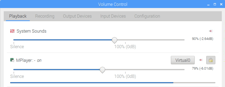
Open pavucontrol either by going to the Raspberry Pi Start Menu -> Sound & Video -> PulseAudio Volume control, or by simply typing "pavucontrol" in at the command line. Click on the Playback tab, and set MPlayer to use the "Virtual 0" audio sink.
Fixing the Time Delay
QRP modes (especially FT8) require the computer's clock to be accurate. This is because signals are expected to be transmitted and received at specific time intervals. Most people use NTP to synchronize their computer clocks to an accurate time. Raspbian automatically syncs to NTP by default if there is an internet connection.
However, the problem is that RTL_SDR, CSDR, and mplayer all running together create an unacceptable time delay from input to output of about 2 - 3 seconds on a Pi 3. Most of the delay comes from the buffering on mplayer which helps prevent underruns when the CPU spikes. WSJT-X expects the packets to be received in the correct time frame, and will not decode them if there are more than about +/- 2 seconds out.
To fix this we need to cheat the clock a bit, and set our system time to always be a few seconds in the past. Thanks to dg0opk for letting us know about this method which involves replacing Raspbians default NTP software with Chrony which is much more configurable. Chrony should have already been installed before in the previous section, installing it automatically disables NTP and activates Chrony. Open it's config file with the following:
sudo leafpad /etc/chrony/chrony.conf
On the first command, edit it to include an offset of about -2.5 seconds.
pool 2.debian.pool.ntp.org iburst offset -2.5
Save and close the config file, then restart the Chrony server with the following.
sudo invoke-rc.d chrony restart
WSJT-X Setup
Now open WSJ-T or JTDX and in File -> Settings -> Audio tab set the Soundcard Input to be "Virtual0.monitor".
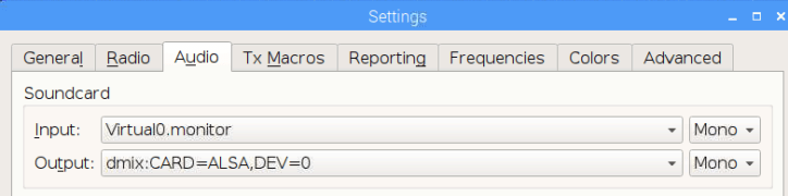
In WSJT-X set the mode to FT8, and you should now be now decoding signals as they come in.
Alternatively you could have opened JTDX instead, using "jtdx" at the terminal. The interface for setting the input sound card is identical.
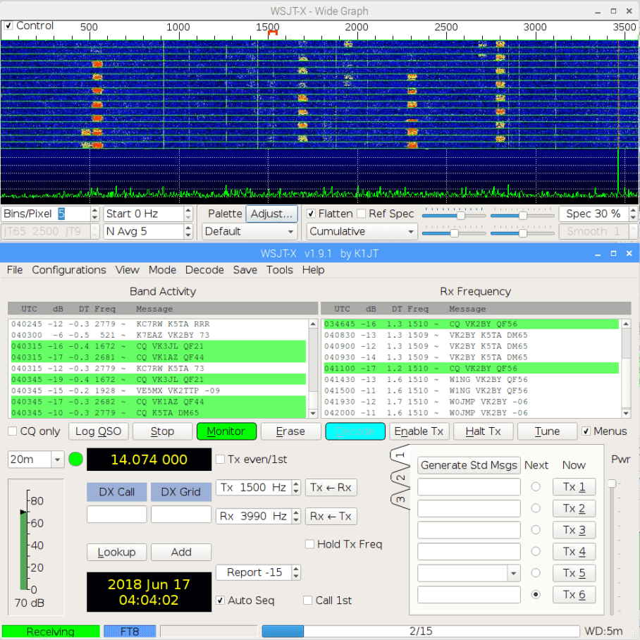
If you don't get any decodes, but are seeing signals in the spectrum, try playing with your time offset in Chrony. You should be able to see if the packets are arriving too early or too late in the WSJT-X waterfall. Once you start getting decodes, adjust the offset time accordingly to try and get the "DT" column values to as close to zero as possible. The DT column lets you know the time offset from perfect timing. E.g. -0.5 indicates that the packet was received 0.5 seconds earlier than expected.
Set up WSJT-X to Report to PSKReporter
WSJT-X can report your spots to pskreporter.info/pskmap, which is a site that aggregates QRP spots from all around the world. Here you can compare your receiver with nearby ones to see how good your antenna and setup is, and to show off how many countries you've received from.
To set it up simply enter your callsign and maidenhead grid details in the General settings of WSJT-X, and then place a check in "Enable PSK Reporter Spotting" under the Reporting tab.
If you're not a ham, you can still contribute to the site as an SWL (shortwave listener). Your callsign can be "hamprefix/SWL/city". There is an example given at https://pskreporter.info. You can find your countries hamprefix here. You can get your Maidenhead grid location from this calculator. Just use the first 4 characters it gives you.
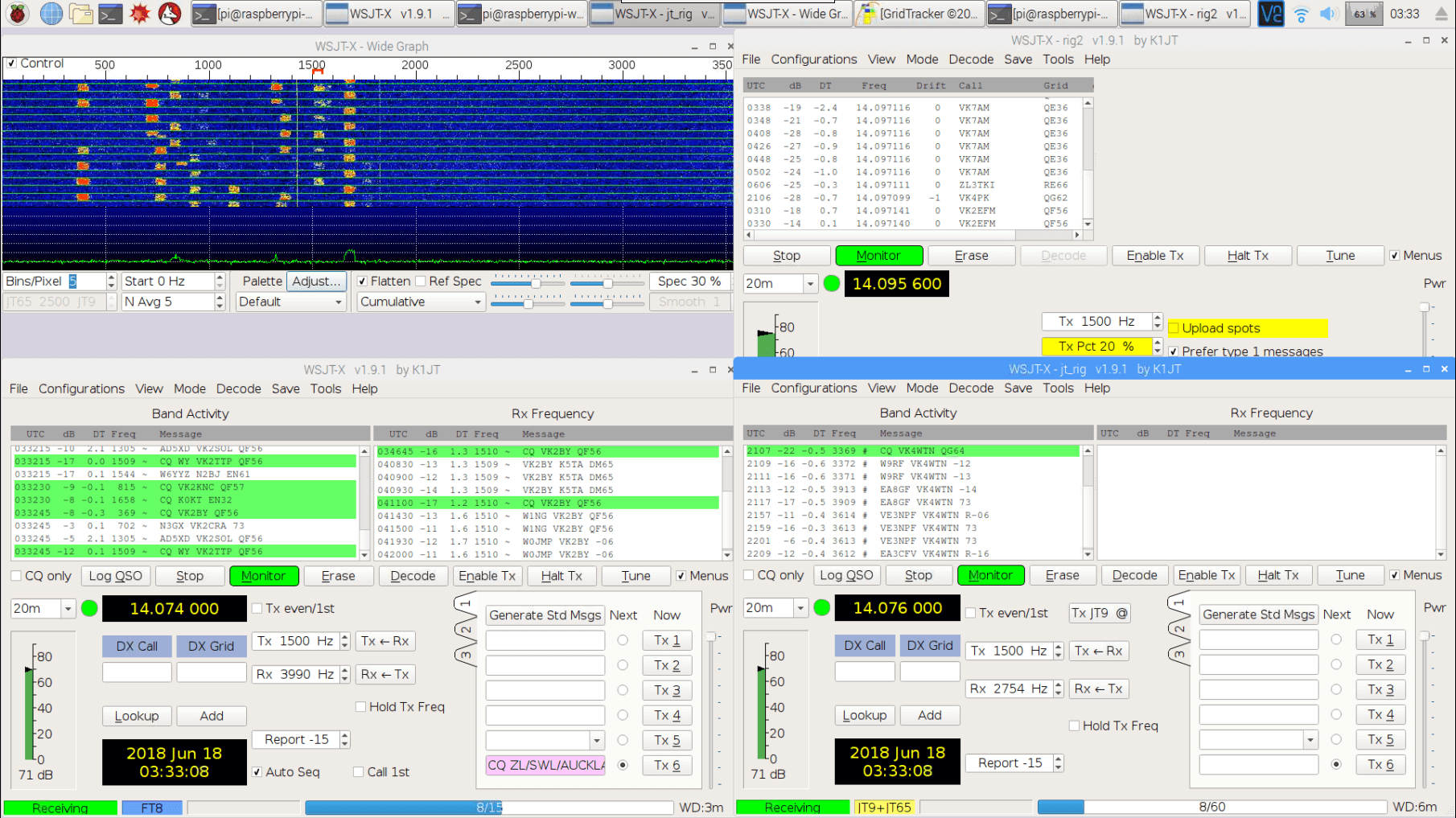
Monitoring Multiple Channels
FT8 + JT9/JT65
Here we'll show how to add simultaneous monitoring for additional QRP modes like JT65, JT9 and WSPR. First we'll show how to set up dg0opk's method that was described in his YouTube video for monitoring just FT8, JT9 and JT65. Since the JT9 and JT65 bands are only a few kHz away from FT8, we can simply open a second instance of WSJT-X, get it to listen to the same audio as the FT8 decoder, and just expand the decoding bandwidth in WSJT-X.
- To do this first open a second instance of wsjt-x by typing in the terminal "wsjtx -r jt_decode".
- In WSJT-X advanced settings, increase the receiver bandwidth to 4500 Hz.
- Set the mode to JT9+J65, and in the waterfall window change the "JT65 2500 JT9" setting to "JT65 4500 JT9".
FT8 + JT9/JT65 + WSPR
Now to monitor WSPR, we'll need to open an actual second channel because the maximum bandwidth that WSJT-X can monitor is 6000 Hz, and WSPR is 28.1696 kHz above the FT8 frequency in the 20m band.
Open a second terminal window and run the ncat command again, making sure to change the tuned frequency. In the example below we change it to the 20m WSPR frequency of 14.0956 MHz.
ncat -v 127.0.0.1 4952 | csdr shift_addition_cc `python -c "print float(14100000-14095600)/1200000"` | csdr fir_decimate_cc 25 0.05 HAMMING | csdr bandpass_fir_fft_cc 0 0.5 0.05 | csdr realpart_cf | csdr agc_ff | csdr limit_ff | csdr convert_f_s16 | mplayer -nocache -rawaudio samplesize=2:channels=1:rate=48000 -demuxer rawaudio -
Open pavucontrol either by going to the Raspberry Pi Start Menu -> Sound & Video -> PulseAudio Volume control, or by simply typing "pavucontrol" in at the command line. Here set the new player to use the "Virtual 1" audio sink.
Open a third instance of wsjt-x with "wsjtx -r wspr". Then set the input soundcard to "Virtual1.montor" and the mode to WSPR. You should be now set up.
On a Raspberry Pi 3 we've been able to successfully open and run two channels and three decoding instances of WSJT-X. If using JTDX we can really only open one or two instances due to its high CPU usage.
Grid Tracker
GridTracker is a nice piece of software that will automatically plot your spots on a map. To use it after installing it using the optional instructions further up, just run ./GridTracker from the command line.
To set up WSJT-X for GridTracker simply go into the Reporting tab of the settings window, and enable "Accept UDP Requests".
Unfortunately it seems that running GridTracker with the two channels and three decoders may be a bit too much for the Raspberry Pi 3 B CPU to handle. If you start seeing missed decodes and buffer underruns in mplayer close GridTracker.
![]()
Tips and Lessons Learned
- We initially tried using sox play and aplay as the audio player. These didn't initially add any large latency, so adjusting the clock wasn't required. However, over time the players would start to display underruns every now and then. Over time the more it underran, the more the latency increased. We're not sure why. If you're running on faster hardware that never underruns, then this may be an easier solution.
- FT8 is definitely the most popular mode and we recommend starting with that. JT9 and JT65 are almost dead.
- Band filters can really help improve reception on the V3. You can find DIY kits from SV1AFN on eBay, or from qrp-labs.com. They require a bit of modification to add a connector however.
- We've had the receiver running stable for 3 days, but the long term stability of the system hasn't been tested yet. Although dg0opk has indicated that his similar setups have been running stable for over half a year.
- You must use an HF antenna. This might simply be a long length of wire (at least about 5 meters). If you're using the multipurpse dipole kit from our RTL-SDR V3 set, then you'll need to extend the length of the arms for HF using two lengths of wire. Simply clamp on about 5 meters or more wire to each leg of the dipole.
- We used a Raspberry Pi 3B. The newer 3B+ may offer improved performance. Overclocking the Pi may also help.


Hi, trying to set this up on a Pi 3, copy paste the rtl-sdr command does not work. After some editing I noticed the –command options are shown as large – sign and pasted that way. So now I am running this command:
rtl_sdr -s 1200000 -f 14100000 -D 2 – | csdr convert_u8_f | ncat -4l -p 4952 -k –send-only –allow 127.0.0.1
This at least starts the rtl_sdr with no errors. I now also get a blue waterfall instead of black in wsjt-x
Um, like every other guide for connecting the Phaser to WSJT-X, this one does NOT SHOW THE RADIO SETTINGS EITHER. Come on guys, get a clue, WSJT-X does not do this for anyone. You have to enter radio settings. What are they for the Phaser????????
i cant get mpalyer to show up in audio devices.
Anyone gotten this to work with an AirspyHF+?
sink_properties=device.description=”Virtual0″ gives:
pi@raspberrypi:~ $ pulseaudio
E: [pulseaudio] main.c: Unknown command: sink_properties=”device.description=’Virtual0PJB’ ”
E: [pulseaudio] main.c: Failed to initialize daemon.
pi@raspberrypi:~ $
I had a fatal error running make on csdr. Missing fftw3.h
Corrected with: sudo apt-get install libfftw3-dev
I should add that I DID all of the steps to this point, icluding:
echo ‘blacklist dvb_usb_rtl28xxu’ | sudo tee –append /etc/modprobe.d/blacklist-dvb_usb_rtl28xxu.conf
and just to check:
cat /etc/modprobe.d/blacklist-dvb_usb_rtl128xxu.conf
blacklist dvb_usb_rtl128xxu
OK, I figured out how to detach the driver:
sudo rmmod dvb_usb_rtl28xxu
It seems to be running though I have yet to decode anything. I need to replace my antenna.
Question: if I want to try to monitor 6m, would the rtl_sdr and ncat commands look like this:
rtl_sdr -s 1200000 -f 50513000 -D 2 – | csdr convert_u8_f | ncat -4l 4952 -k –send-only –allow 127.0.0.1
ncat -v 127.0.0.1 4952 | csdr shift_addition_cc `python -c “print float(50513000-50313000)/1200000″` | csdr fir_decimate_cc 25 0.05 HAMMING | csdr bandpass_fir_fft_cc 0 0.5 0.05 | csdr realpart_cf | csdr agc_ff | csdr limit_ff | csdr convert_f_s16 | mplayer -nocache -rawaudio samplesize=2:channels=1:rate=48000 -demuxer rawaudio –
OK, I had to upgrade to Raspbian Buster which has set me back a bit. Now when I issue the rtl_sdr command, I get:
Using device 0: Generic RTL2832U OEM
Detached kernel driver
Found Rafael Micro R820T tuner
Enabled direct sampling mode, input 2
Enabled direct sampling mode, input 2/Q.
Sampling at 1200000 S/s.
Tuned to 14100000 Hz.
Tuner gain set to automatic.
Reading samples in async mode…
Allocating 15 zero-copy buffers
Signal caught, exiting!
Signal caught, exiting!
Short write, samples lost, exiting!
User cancel, exiting…
Reattached kernel driver
Any help would be appreciated.
Got as far as:
rtl_sdr -s 1200000 -f 14100000 -D 2 – | csdr convert_u8_f | ncat -4l 4952 -k –send-only –allow 127.0.0.1
Found 1 device(s):
0: Realtek, RTL2838UHIDIR, SN: 00000001
Using device 0: Generic RTL2832U OEM
Kernel driver is active, or device is claimed by second instance of librtlsdr.
In the first case, please either detach or blacklist the kernel module
(dvb_usb_rtl28xxu), or enable automatic detaching at compile time.
usb_claim_interface error -6
Failed to open rtlsdr device #0.
How do I detach the old driver so that this will run?
I have reached the same issue. Did anyone fix this till now?
Pulse audio wont load “Establishing connection to PulseAudio. Please wait…”
Please check the line above “-mtune=coretx-a53”
That looks like a typo to me.
Thanks!
Thanks, have fixed that up.
By reading through this guide and the comments section I’m now up and running on 2m with the following single command line:
rtl_sdr -s 1200000 -f 144165000 -g 60 – | csdr convert_u8_f | csdr fir_decimate_cc 25 0.05 HAMMING | csdr bandpass_fir_fft_cc 0 0.5 0.05 | csdr realpart_cf | csdr agc_ff | csdr limit_ff | csdr convert_f_s16 | mplayer -nocache -rawaudio samplesize=2:channels=1:rate=48000 -demuxer rawaudio –
Note:
My particular USB dongle is -9KHz off the desired frequency; until I realised this (by visualising the spectrum with the SDR software Gqrx) I was using the stated 2m FT8 frequency of 144174000 to no avail.
I have this running well on a Raspberry Pi 2B (a01041) with WSJT-X v2.0.0
Andy, M0CYP
From N1OFZ:
Would like to use this to monitor FT8 on 6m and possibly 2m. So I’m trying to modify your setup but I don’t think I’m quite there yet as I’m not decoding anything. First I modified the rtf_sdr line to read: rtl_sdr -s 1200000 -f 50313000 – | csdr convert_u8_f | ncat -4l 4952 -k –send-only –allow 127.0.0.1
I removed the -D 2 as since it’s VHF and the dongle should receive this freq natively. Let me know if this is incorrect thinking. I then modified the cat line as follows: ncat -v 127.0.0.1 4952 | csdr shift_addition_cc `python -c “print float(50313000-50287000)/1200000″` | csdr fir_decimate_cc 25 0.05 HAMMING | csdr bandpass_fir_fft_cc 0 0.5 0.05 | csdr realpart_cf | csdr agc_ff | csdr limit_ff | csdr convert_f_s16 | mplayer -nocache -rawaudio samplesize=2:channels=1:rate=48000 -demuxer rawaudio –
After a bit of playing with things I have it working on 6m. First remove the -D 2 from the rtf_sdr line as I have done in my prior comment. Second remove “csdr shift_addition_cc `python -c “print float(50313000-50287000)/1200000″` | ” from the ncat line and it works! To figure this out I ran my transmitting FT8 setup into a dummy load. I ran the dongle into the whip antenna that came with it. I used gqrx to determine that the dongle/pi was receiving properly as well as the audio redirects. My dongle was receiving dead on freq! It had been running for more than a day so I assume it should not drift. I then fired up wsjt and was still not seeing my signal. So I looked at the cdsr stuff again and figured that there was no reason to offset the frequency in my case (ymmv). As soon as I did that I immediately started decoding some local FT8 traffic!
Next on my list is to write a shell script to combine the rtf_sdr and ncat lines into one executable that also launches wsjt. By doing that I can also likely remove the ncat code as well. Has anyone tried to connect to the ncat stream remotely? I was thinking of remotely mounting the pi near the antennas and decoding the wsjt data in the shack. I guess it’s not really necessary as I can connect to the pi via vnc but I was thinking I could run the pi in cli mode and run two dongles, one for 6 and one for 2.
Using your suggested changes to the rtl_sdr and ncat commands to monitor 6m but not able to decode anything. It may be my antenna but perhaps someone could have a look here to see if this looks about right:
https://imgur.com/a/5oOvHuY
Thank! W2IHF
You might try running rtlsdr-wsprd (https://github.com/Guenael/rtlsdr-wsprd). No virtual audio or other add ons, and it consumes less than 5% of the Pi’s CPU
Already done, I wanted to receive the WSPR with this project …
My screenshot: https://it9ybg.blogspot.com/2018/07/monitoring-station-with-rtl-sdr-v3-and.html
I did everything on Raspberrypi2. The CPU works around 30% receiving only FT8. But I receive a few packages, the reception is very hard. I have also played with chrony but I receive little even the FT8 signals are present. In WSPR no decoding with signals present. Some idea?
What’s your DT like on the decoded messages?
I partly solved my problem with FT8 mode. I increased the string to the value of -3: pool 2.debian.pool.ntp.org iburst offset -3. Now the DT of the received signals is almost zero. The FT8 mode is now ok. I relaunch WSJTX with only WSPR mode (1 instance only) and, with the same settings, I do not see any wspr transmitting stations, even though the signals are strong in the waterflow. The HF antenna is a 20-meter rotating dipole and a 40-meter dipole antenna. Tips? Do you think that JTDX is more sensitive in WSPR? Thank you
Thanks for this tutorial. Hadn’t realized that the blog v3 was actually this good in direct sampling mode. My v3 FT8 monitor is running great right now even without a filter.
1) Try this in the modprobe file:
alias snd-card-0 snd-aloop
options snd_aloop id=loop0
This is also the only parameter that is required
(this renames the device name so I can use pcm “hw:loop0,0,0″ instead of the default name:”Loopback”).
index parameter fixes the device number, so that it shows as card 8 when you type in aplay -l.
enable=1,1 enables the two loopback cards and pcm_substreams sets the number of pcm-s on each card.
2&3) I’m not sure why the first one does not work and the second does, both are the same
and I have tried it here without issues.
Do note that this is not optimal as can be seen from the aplay output: “Slave: Linear Integer Linear Float conversion PCM (FLOAT_LE)”
You either run it with: aplay -v -r 96000 -f FLOAT_LE -D wsjtx_alsa or you can change the
slave parameters in the asound.conf to match your sample rate and format.
3) If you want multiple programs to read from the device you will have to create a “dmix”
device for it.
This config is the absolute bare bones, as I’m piping the inputs and outputs to Jack and I wanted the least amount of buffering and latency. You can find an example of how to do it
here: “https://alsa.opensrc.org/Jack_and_Loopback_device_as_Alsa-to-Jack_bridge”
Just note that the author (and every other tutorial online) missed the fact that every subdevice is full duplex, so they all do a sub optimal setup.
Great tutorial, I haven’t used csdr before so this is quite useful for my setup.
A tip: you can remove PulseAudio and probably reduce CPU usage by using snd_aloop.
A part of my setup: https://pastebin.com/DPHTHiQk
Thanks for the tip! I tried your config and it does seem to save the 20% CPU that PulseAudio sucks up on the Pi3. If I use aplay with straight ALSA it also seems to fix the constant underrun problems I had before with aplay, and the time delay is much less.
But i’m having some problems with setting up the full system, hopefully you can help.
1) More of a question: “options snd_aloop index=8,9 id=loop0,loop1 enable=1,1 pcm_substreams=8,1” doesn’t seem to run on boot alsa.conf. I got around it by manually running “sudo modprobe snd_aloop index=6,7 id=loop0,loop1 enable=1,1 pcm_substreams=8,1”
I had to change index=8,9 to index=6,7 for it to recognize the command. What exactly is the index specifying? Also If I change the index in alsa.conf, it still won’t run on boot.
2) Trying to use “aplay -v -r 48000 -f S16_LE -Dlinrad_alsa” always gives me a “hardware is busy error”
3) “aplay -v -r 48000 -f S16_LE -Dwsjtx_alsa” works fine, and in WSJTX I select “wsjt_jack” to listen to it which works perfectly. But if I open a second instance of WSJTX and try to listen to wsjt_jack again (to monitor JT9+JT65), it gives an error “Error in Sound Input: Requested input audio format is not supported on device).
Sorry for the top post answer, browser restart …