Using our new Dipole Antenna Kit
Over on our store we now sell our dongles with a receive only dipole antenna kit that replaces the older magnetic whip style antennas from the previous kit. This was done for a few reasons
- We believe that the dipole kit is much more versatile and will enable beginners to get better reception straight away
- Magnets of any type are difficult to ship as they are not allowed by many airmail carriers.
While the magnetic whip still works perfectly fine, the dipole kit should make it easier to get the antenna outside or in a better position away from noisy computers/electronics, and it also allows for a simple v-dipole configuration for satellite reception.
The units are currently in stock at our Chinese warehouse either bundled with an RTL-SDR or as an individual antenna set.
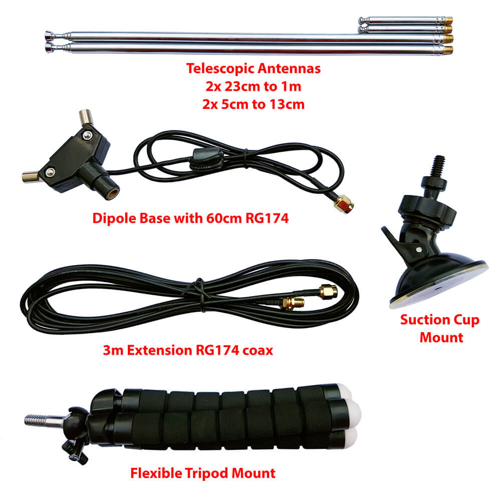
This post is a guide on how to use the dipole antenna set in various configurations. First we'll show and explain about what's included in the set:
- 1x dipole antenna base with 60cm RG174 cable and SMA Male connector. This is the dipole base where the telescopic antennas connect to. The short run of RG174 is decoupled from the base elements with a ferrite choke. This helps to prevent the feed line from interfering with the dipole radiation pattern. The dipole has a 1/4 inch female screw on the bottom, which allows you to use standard camera mount products for mounting.
- 1x 3 meter RG174 coax cable extension. This coax cable extension allows you to mount the antennas in a place that gets better reception. E.g. outside on a window, or higher up.
- 2x 23cm to 1 m telescopic antennas. The telescopic dipoles are detachable from the dipole base via a M5 thread which allows for greater portability and the ability to swap them out. These long telescopic antennas cover VHF to UHF.
- 2x 5cm to 13cm telescopic antennas. These smaller antennas cover UHF to 1090 MHz ADS-B, and even still work decently up to L-band 1.5 GHz frequencies.
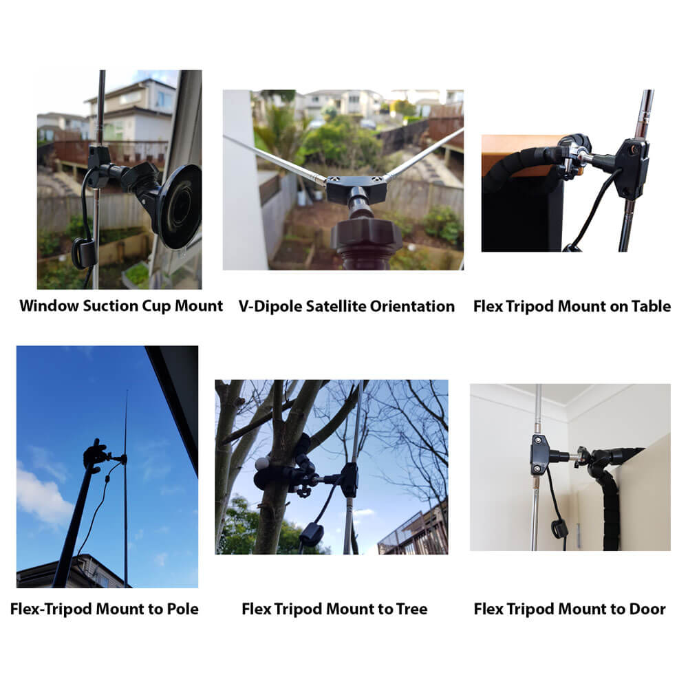
- 1x flexible tripod mount with 1/4" male screw. This piece allows you to mount the dipole on a variety of different locations. E.g. a pole, tree branch, desk, door, window sill. The legs of the tripod are bendy and rubberized so can wrap securely around many objects.
- 1x suction cup mount with 1/4" male screw. With this mount you can mount the dipole on the outside of a window, on a wall, car roof/window, or on any other smooth surface. To use first clean the surface with window cleaner or isopropyl alcohol. Then place the suction cup on the cleaned surface and close the lever to activate the suction.
Dipole Orientation
Signals are normally transmitted with either horizontal, vertical or right hand/left hand circular polarization (RHCP/LHCP). This is essentially the 'orientation' of a signal, and an antenna with the same polarization should be used too for best performance. A dipole can be used in either vertical or horizontal polarization, just by orienting it either vertically or horizontally.
If you mismatch vertical and horizontal polarization or RHCP and LHCP you'll get an instant 20dB loss. If you mismatch vertical/RHCP, vertical/LHCP, horizontal/RHCP, horizontal/LHCP you'll only get a 3dB loss.
For vertical polarization, in theory it does not matter which way around you orient the antenna as long as it's vertical. However in practice, you may get slightly better results by having the element connected to the center coax conductor pointing UP. You can confirm which element is connected to the center conductor by temporarily removing the black lid on the dipole base (it can be easily pried off with a nail or flat head screwdriver).
There are also ways to optimize the radiation pattern with dipoles. For example for LEO VHF satellites you can use a V-dipole configuration. You can also make a somewhat directional antenna by using a bent dipole configuration. Some more examples of dipole configurations can be found on KK4OBI's page on bent dipoles.
Terrestrial Signal Reception
Most signals broadcast terrestrially (on Earth) are vertically polarized.
To use the dipole for vertically polarized signals, all that you need to do is orient the elements vertically (up and down).
In theory there is no up and down for the dipole when used in the vertical orientation. However in practice you may find slightly better performance when the 'active' element points up. The active element is the one connected to the center conductor. You can check which element is connected to the center conductor by removing the top cap on the dipole base. This will let you look inside at the connections.
Satellite Reception
The dipole can be used in a V-Dipole configuration for polar orbiting satellite reception. See Adam 9A4QV's post where he wrote about how he discovered that it was possible to use dipoles in this configuration for excellent satellite reception. The idea is to use the dipole in horizontal polarization. This gives 3dB loss on the RHCP satellite signals, but also nicely gives 20dB loss on terrestrial signals which could be overloading your RTL-SDR.
For 137 MHz satellites like NOAA and Meteor M2 extend the larger antenna elements out to about 53.4 cm each (about 2.5 sections). Angle the dipole so it is horizontal and in a 'Vee' shape, at about 120 degrees. Place the dipole in the North-Source direction.
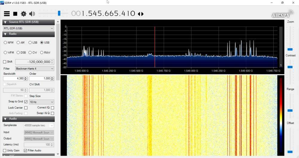
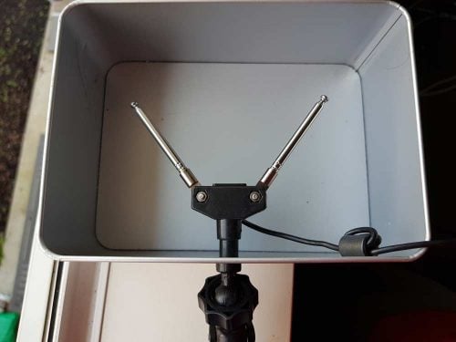
With an appropriate L-band LNA like the Outernet LNA the dipole can also somewhat work to receive L-band satellites. Using the smallest antenna collapsed, use a V-dipole configuration and point it towards the L-band satellite. Ideally use a reflector too. In the image below we used a simple cookie tin as a reflector. A hole was drilled into the center and the mount used to clamp in the antenna. This together with the Outernet LNA was enough to receive AERO and STD-C.


Choosing the Antenna Element Length
Like with the whip you can use an online calculator to calculate the optimal length for your frequency of interest. We recommend this dipole calculator. The exact length does not matter too much, but try to get the lengths as close to what the calculator says as you can. With the dipole you want both elements to be the same length.
In reality extending the antenna to almost any random length will work just fine for most strong signals. But if you're really trying to optimize those weak signals you'll want to fine tune the lengths.
Basically the longer the antenna, the lower it's resonant frequency. The shorter the antenna, the higher the resonant frequency. You want to be close to the resonant frequency. Remember that there is about 2cm of metal inside the antenna itself which needs to be added on. Below is a cheat sheet for various lengths and frequencies. Note that the length refers to the length of one side of the dipole only (e.g. the length that you need to extend each element out to).
- Large Antenna, 5 Sections, 100cm + 2cm is resonant @ ~70 MHz
- Large Antenna, 4 Sections, 80cm + 2cm is resonant @ ~87MHz
- Large Antenna, 3 Sections, 60cm + 2cm is resonant @ ~115 MHz
- Large Antenna, 2 Sections, 42cm + 2cm is resonant @ ~162 MHz
- Large Antenna, 1 Section, 23cm + 2cm is resonant @ ~ 285 MHz
- Small Antenna, 4 Sections, 14cm + 2cm is resonant @ ~445 MHz
- Small Antenna, 3 Sections, 11cm + 2cm is resonant @ ~550 MHz
- Small Antenna, 2 Sections, 8cm + 2cm is resonant @ ~720MHz
- Small Antenna, 1 Section, 5cm + 2cm is resonant @ ~1030 MHz.
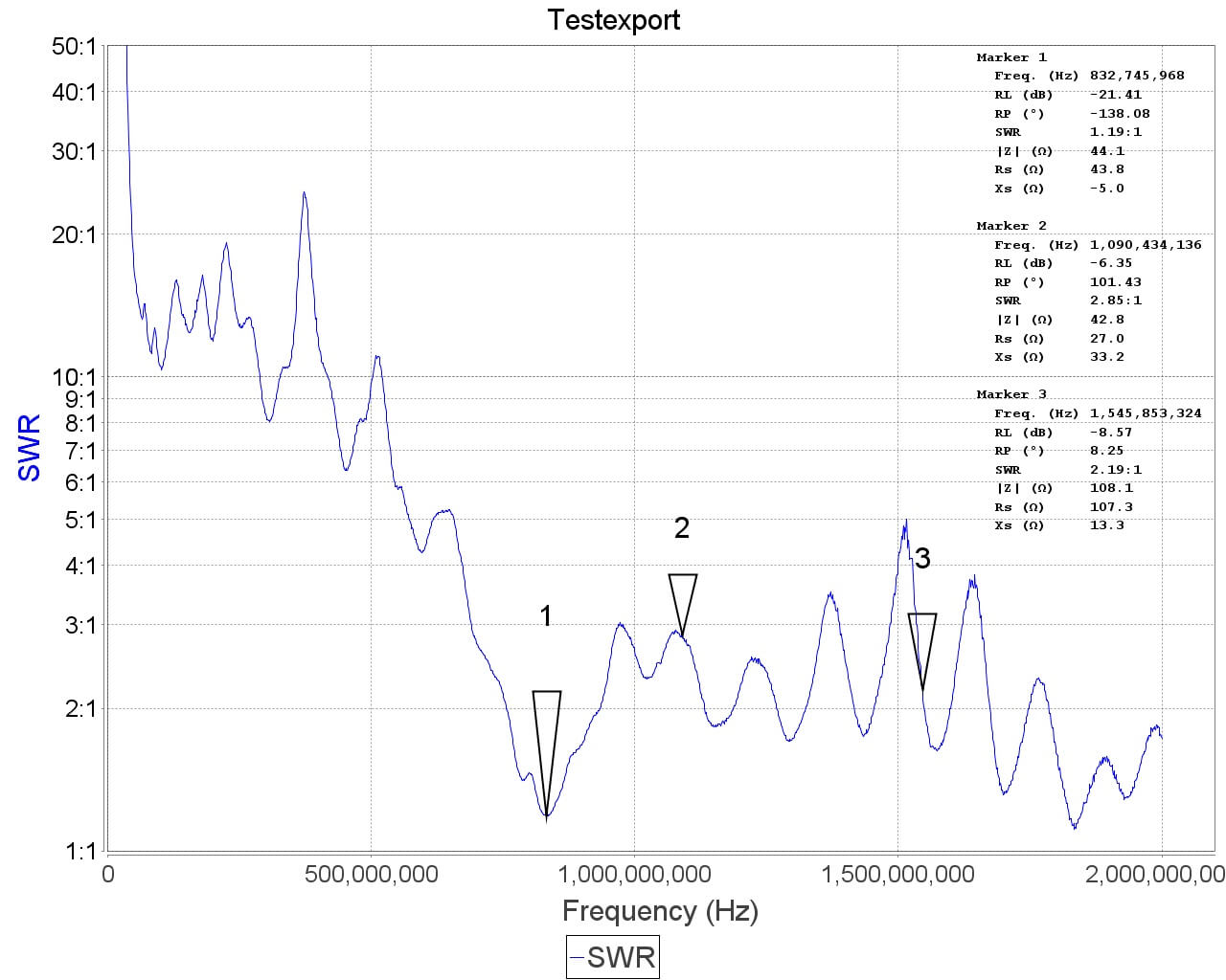
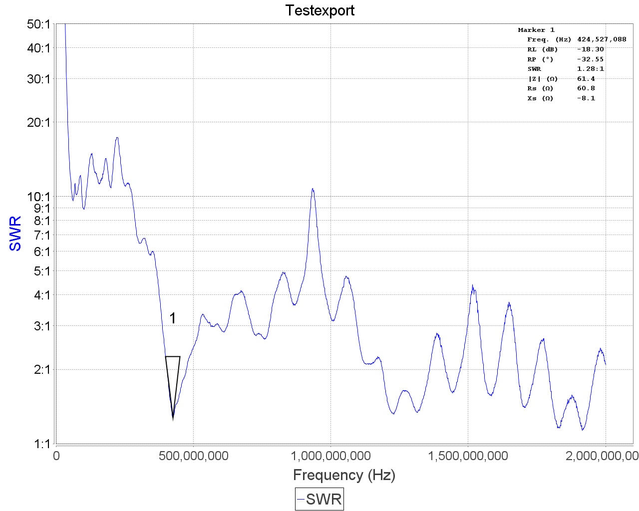
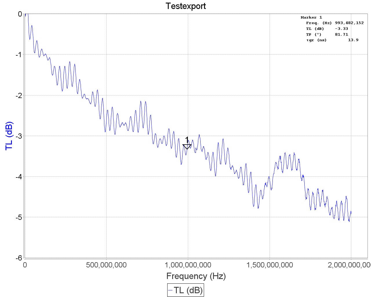
See the SWR plots at the end for a more accurate reading of the resonance points. But in most cases no matter what you extend the length to the SWR should be below 5 at most frequencies which results in 2.5 dB loss or less. More accurate info on VSWR loss graphs can be found in this document from the ARRL "Understanding SWR by Example" (pdf).
Using the Mounts
The suction cup mount allows you to easily place the antenna on a window, or any smooth surface. To use it first clean the surface thoroughly with isopropyl alcohol or glass cleaner. Then apply the suction cup and close the lever to lock it in place. The lever requires some force to push down, and this ensures a strong grip. You can then angle the antenna in the orientation that you need using the ball socket. Once in place close the ring to lock the ball socket in place.
The flexible tripod mount is useful to mounting the dipole to almost everything else. Including tables, doors, poles, trees etc. The legs of the tripod have a flexible metal wire inside and rubber sheath so they can be bent into a position to grip almost anything.
Note that the mounts and RG174 extension allow you to more easily use the dipole antennas outside or in a better indoors position (e.g. on a Window). But please note that like our older magnetic whip we do not recommend permanently mounting this antenna outdoors. This antenna is designed to be a portable antenna that you put up and take down at the end of the day - not for permanent outdoor mounting. It is not protected against water, not grounded so cannot handle a lightning strike and could be damaged with dirt and grime build up. For permanent outdoor mounting you could conceivably fill the inside and hinges of the dipole with silicon putty or maybe even hot glue and ground the antenna yourself, but we have not tested this. The stainless steel antennas won't rust, but dirt and grime could gum up the collapsing mechanism.
Tightening the hinge
Once you've got the orientation of the dipoles the way you want, you might want to tighten the hinge so the elements don't move so easily anymore. To do this simply take a small screwdriver and tighten the screw on the hinge.
ESD Bleed Resistor
Note that our older antennas had a 100kOhm ESD bleed resistor between the two elements. This is no longer the case on newer models. The purpose of the resistor was to slowly bleed any ESD buildup to ground.
We decided to improve ESD protection on the dongle instead, so the ESD bleed resistor is not longer required and is now omitted on newer productions.
Sample VSWR Plots


Other Notes
Note that this is NOT an antenna designed for TXing. It is an RX antenna only. So please do not TX with it unless you really know what you are doing as you could damage your TX radio.


These kits are very cheaply made and should not sell for more than $10, they would be ok at that price. Unfortunately many unscrupulous sellers gouge people for 2-3 X this much for these. Buyer beware of who you are dealing with, and SHOP AROUND before you buy anything these days.
Is it safe to transmit with an amateur radio (e.g., YAESU VX-6R) near the RTL-SDR antenna (e.g., within 1 meter)? Amateur radios usually have a default transmit power of 5-10W. Will this damage the RTL-SDR? Especially when the RTL-SDR is monitoring almost the same frequency.
not an expert, but also a ham.
No, it’s not safe. Transmitting 5–10 W from a handheld like the Yaesu VX-6R within ~1 m of an RTL-SDR antenna can easily overload or permanently damage the SDR’s very sensitive front end, especially if the SDR is monitoring the same or a nearby frequency. Even small amounts of coupled RF can exceed the SDR’s safe input level; to avoid damage, keep several meters of separation (preferably 5–10 m), use strong band-pass filtering or an RF limiter, or disconnect the SDR antenna while transmitting.
73! PU2XIK
can I use a long wire to suppliment the included attena
Yes, I did. The included one is not near long enough for a lot of applications.
which antenna should be used below 30 MHz
Ham Radio 40m=7.0-7.3 MHz | 20m=14.0 MHz-14.3 MHz | 10m=28.0 MHz -29.7Mhz
The dipole has very poor reception characteristics outdoors.
Is it possible to use a loop antenna or will the RTL-SDR USB stick be destroyed due to overload?
or what possibilities do you have to receive these frequencies?
You can use Mla 30 plus which is a loop antenna
Folks apols for the naivety of my question; shall I install drivers for a Mac (Intel processor; an iMac)? I am not super clear about this from the instructions above
On Mac the drivers are usually embedded within the package file. So no need to install anything other than the software you choose. I recommend SDR++ or GQRX.
The ferrite choke is too far the coax from the antenna. This causes common mode current to flow along the coax (from the antenna to the ferrite choke) and can degrade the dipole performance.It was probably easier for them to manufacture that way. Move the choke towards the antenna, about an inch away. Also extend the coax at the right angle from the center of the dipole if possible. To move the choke carefully re-feed twin loops through the ferrite towards the antenna. I love this antenna, well done!
Hi, in my dipolo antenna bought with your kit I have a100k Ohms resistor connected between the two conductors. It is correct? In some photos by other users I don’t see any resistor.
Thank you.
Yes it’s correct. Some older sets have the resistor, which is a simple ESD bleed resistor. On newer units we no longer include the resistor, as we now rely on improved ESD protection within the dongle itself.
good morning and happy holidays! in my dipole (which has the resistor) if I touch one side of the antenna with a tester tip I get conductivity both if I touch the central pin of the connector with the other tip of the tester and if I touch the outside of the connector… like it’s shorted it would seem…is that correct?
Guido,
I suspect this might be a manufacturing defect. If you reach out to them via email, they may be able to help by sending a replacement dipole. They did for me. Send a supporting photo if possible.
Your instructions say, “However in practice, you may get slightly better results by having the element connected to the center coax conductor pointing UP. You can confirm which element is connected to the center conductor by temporarily removing the black lid on the dipole base.” But when I looked at mine, it appears both elements are connected to the coax wire.
Both dipole elements should be connected to the coax, but there are two wires in the coax to differentiate between.
One wire is in the center, and surrounded by a white plastic sheath. That’s the center conductor.
The other is the shield wire, and it is wrapped around the outside of the white plastic sheath.
So in the dipole the center conductor connects to one element, and the shield wire connects to the other element.
Wow, thanks for a speedy response on an old thread. To my aged eyes it appears all wire strands are touching the contacts for both elements. https://photos.app.goo.gl/hTj79PVpf6Ky1SbY9 Keep in mind you’re having a dialogue with a total newbie.
Hi there, just jumping in and looking at your photo, center center conductor looks to be on the left, and the grounding wires sheath looks to be on the right. I may be wrong of course, but in case you were still stuck. Cheers!
Thanks Doyle, since the exposed strands looked like they were touching each other, I slipped a small piece paper between them to insulate, then I used an ohm meter to solve the which-is-which problem. Should have thought of that much sooner actually. Thanks again.
Ah yes this is something else. Looks like a defect when the factory manufactured it. The outer coax braid should not be touching the other side. You can push it over so it doesn’t touch, or just contact us at admin rtl-sdr.com for a replacement to be sent out.
I am trying to locate a connector for the device. What is the female connection?
The replacement unit arrived. Thank you very much.
You can easily use a multimeter to determine which element is connected to the center conductor. It is easier to do this with the shield. Just set up your multimeter for conductivity or resistance. Touch one lead to the shield collar and determine which antenna element is connected to the shield. Then the OTHER element will be connected to the center wire.
These SDR’s are cheap crummy Chinese Junk
What kind of cheap crummy junk are you?
Can I assume the example of 80cm implies measuring the telescopic element from tip to socket screw-in point, and 2cm to the swivel nut?
The link to the dipole calculator is not working. Here is an alternative:
https://www.omnicalculator.com/physics/dipole
I think you can start with GQRX. THat’s what I’m using on Linux and, I don’t klnow a lot about Mac but It’s running a Linux Kernel in the background.
For other informations (installation, use, …), there are plenty of tutorials. Google is your friend 😉
MacOS does not use a Linux Kernel, it uses the XNU Kernel: https://github.com/apple/darwin-xnu
I am an absolute beginner at anything Ham related. But I thought I’d buy an RTL-SDR v3 as a beginning step.
Things I’d like to know.
What is in your opinion the best online source for learning about Ham and/or SDR and antennas?
Also, will an HDTV antenna work for my purposes?
What’s the best software to use? I have an OSX Macbook Pro
Best place to start learning about Ham is ARRL.ORG
To determine if an HDTV antenna will work, we have to know what you are trying to do. Pretty much any antenna will allow you to receive something, but matching the frequency and polarization to the signal of interest will give the best results.
I use Airspy software.
I am an absolute beginner at anything Ham related. But I thought I’d buy an RTL-SDR v3 as a beginning step.
Things I’d like to know.
What is in YHO the best online source for learning about Ham and/or SDR and antennas?
Also, will an HDTV antenna work for my purposes?
What’s the best software to use? I have an OSX Macbook Pro
I new to radio. I have my RTL-SDR setup and for basic testing FM radio fine but AM not coming in. Tired both sets of antennae and repostioned the antennae many, many different way. Is it a setting in the SDR# that I am missing?
For AM reception see “Feature 1: Direct Sampling HF Mode” at https://www.rtl-sdr.com/rtl-sdr-blog-v-3-dongles-user-guide/. Also you’ll probably need a different antenna such as an AM loop antenna commonly used by stereo receivers or better yet a passive tunable loop antenna such as the AN-100 or AN-200.
You can also get an upconverter to convert the lower HF frequencies to VHF or UHF.
You will need a much longer antenna then the RTL-SDR dipole for good performance on HF or AM broadcast. A long piece of hookup wire works fine.
Bought a two foot section of 1/4 inch threaded pipe hanging rod and an adapter and have managed to make a 2 foot standoff for the dipole while on the little suction cup mount. I was afraid it would be too heavy for the suction cup but it has stayed up in place for over two days now in the wind.
Just a thought on a future enhancement to the antenna kit!
Re the RTL Dipole antenna kit….Can this antenna set be used with the Hackrf One? If so…. Can it be directly connected or does other protection equipment need to be in-between the antenna and Hackrf One? I am a newbie, have purchased the above antenna set, and am now having doubts about what I am doing. Thanking repliers inanticipation.
Hey just bought this set, never tinkered in radio yet thank you for making it affordable to get into
I m trying to interface a late model SDR to a 9db hi-gain external aerial. The down feed is RG6.
My problem is: I cannot find a suitable connector.
It appears to me a miniature SMA connection but searches for SMA-RG6 always bring up the large SMA connector. I can’t even make suitable mix- and match designs so I am stuck. Please advise. Thanks
You may need a SSMA to SMA adapter if it is “mini-SMA”.
What is the best way to position the dipole for analog tv in the US? I’m using it as a temporary setup until we move when we have a roof antenna.
In the US over the air TV is horizontal polarized. Analog is gone but digital TV is here.
Will the dipole antenna work with 433 MHz devices (for like door and window and PIR motion sensors), and if so what is the best configuration for that?
Yes. You wanna use an antenna that’s 0.165m. I found this website helpful for giving you a scaled image. https://sheldont.github.io/Antenna-Length-Calculator/
My bad, turns out those graphics aren’t to scale so I wrote my own. https://codepen.io/Haggleforth/full/yyBPwxN
Run it in a fullscreen debug mode for maximal length. If the antenna’s length is bigger than the diagonal of the viewport it’ll divide by 2 until it fits.
If you read the console messages, it’ll tell you the full length in inches.
Thanks for the information – would it be possible for you to pass me the data for the VSRW plot for the long extended antenna? I’ve included my email in “notify me of response”, if you can’t access/see that let me know. I’m working on a class project and would like quantifiable VSRW values per frequency.
Hello, this antenna is not for HF right?
Can I use the “base” and add something like a wire acho side to make my own HF dipole?
The included elements aren’t long enough for HF. But your thinking is right. You could indeed extend the length by clamping in much longer wires to make an HF dipole.
Thanks admin
admin
Good day people, I have constructed the QFH antenna.Please is it ok connecting the QFH antenna directly to the V3 RTL with out any limiting resistor or balun. Secondly, I am having a challenge getting the SMA connector, So is it also ok opening up the dipole antenna(that came with V3 RTL) and connecting the QFH feed to it with the resistor and balun intact before connecting it to the V3 RTL.
Yes you can connect a QFH directly to the V3, and you could repurpose the dipole base into a connector for your QFH without problems..
Not bad, but the threads were damaged on the long dipole elements, so they don’t screw in easily. Also, the dipole doesn’t fit the threads on the tripod for some reason.
Please contact us at admin rtl-sdr.com if your kit has a defect. We’ve seen about a ~1.7% defect rate over the last few batches which IMO is too high, but we’re working hard with the factory to reduce defects.
I am also having the same problem. One of the elements isn’t threaded at all. Very unfortunate as this was a gift for my 9 year old son. It looks like I’ll need a replacement part.
You cross threaded them ya incompetent knucklehead. hahahahahahhahagahahaha.
Evidently you don’t know who you’re talking to, nor what you’re talking about. This is a very old post. I was in contact with the supplier here who was nice enough to confirm this was not my issue. There was a bad batch that was sent out and needed to be replaced. I sent photos to the supplier as proof of no threading whatsoever, and they confirmed the issue. They sent me a replacement kit without charge – which didn’t have the issue. So Bill_SFFS perhaps next time you should check your attitude before making a fool of yourself…
Billy_SFFS,
No need for those types of comments. You can see yourself out.
Guys, don’t feed the trolls, they are sufficiently plentiful here…
Let them starve !
This antenna is quite good at RDFing. It arrived today and I’ve already tracked down a 937 MHz transmitter 15 km away and a 450 MHz signal 85 km from me.
I hope that you are still working on the triple coherent receiver project – this dipole is good, but a proper RDF setup would be better!
A really nice, and much-needed versatile antenna kit! I have two questions about it:
1) In vertical dipole mode, doesn’t it matter which dipole points up (i.e., shouldn’t the grounded element point down to the earth)?
2) Would this type of antenna work better with a balun, and if so, could I modify this kit to work with one?
Thank you.
Sorry about the delayed reply
1) Yes the grounded element should be pointing down. You can confirm which element connects to which part of the coax by removing the top cap on the dipole base (it’s easy to remove and put back).
2) A balun could help if you have a specific frequency that you’re interested in. The dipole already has a choke on it to help prevent the cable being used as an antenna element.
Thanks for this kit the antenna is working perfectly. I mount it up on my porch as a v-dipole as NOAA comes over, and then back to a vertical dipole for everything else. Works waaay better than the little whip I got with my old dongle and even better than the pizza pan planar disk in my attic sometimes.
Anyone had succes with this dipole antenna and weather satellites? I made sure that the satellite NOAA15, NOAA18 or NOAA19 are in reach (website: https://in-the-sky.org/satpasses.php?day=16&month=11&year=2017&mag=900&group=1&anysat=v2&s=NOAA+15&dl=dl), oriented the dipole antenna in 120degress horizontally facing north/south outside on my balcony with clear sky. Tuned the RTL-SDR onto around 137MHz with gqrx (FM mode) but I don’t see a single peak that resembles a weather satellite signal. I was watching around from 135MHz up to 139MHz but nothing. Only thing I see are plenty of AM communication from nearby planes. Anyone had luck with this dipole antenna?
Yeap, it works fairly well. You should calculate the exact length for both elements of dipole (don’t forget to substract 1 cm from both elements, because 2 cm is in the base). Place the antenna horizontally in V position, 120°, then you want to reduce sample rate of your dongle to filter out airband signals. Then you need to adjust gain parameters (for GQRX on Linux/Mac OS use r820tweak utility from github) or turn AGC on (may cause overloads – 8 bit is 8 bit). For the best results use LNA, such as LNA4ALL, but switch off AGC in this case and adjust gain manually.
I get nice pictures with this dipole with both v3 dongle and Airspy R2 being located near the airport. Rule of the thumb – tackle with gain settings.
Amigo,pienso que necesitas filtrar las frecuencias que interfieren con un dispositivo específico para esa frecuencia.
I got lucky when bought it on last Monday. I didn’t expect it’s selling out so fast.
I got one question though. Will if perform well if I put it onto the window from the inside (in vertical polarization of course)? I just don’t want to squeeze the coax with window frame to get it onto the outside part.
Oh come on I’ve waited since the first time you wrote about this for buying it and it’s sold out in hours 🙁
Please try to make it again available in less than 1-2 months as you wrote…
Already sold out!
$10 is too cheap for this package.
I’d pay nearly that for the bendable tripod, that’d be awesome for PCB yagis etc on the go. Great deal for sure!
Ouch, the initial demand was a lot higher than expected! Working on getting more made asap.
Firefox does not display the images and if i save them IrfanView tells me why
Hmm interesting, looks like IE and FireFox both have incompatibility problems with the new webp standard. Only Chrome renders them properly if they’ve been converted. I’ve turned webp conversion off for now.
Safari is still broken, but I can view it with Chrome. Looks like a great product that solves a lot of my problems. Looking forward to ordering when available.
Same here in Firefox. Search WebP on Wikipedia. Excerpting:
WebP is an image format employing both lossy and lossless compression. It is currently developed by Google, based on technology acquired with the purchase of On2 Technologies.
Both Google and (previously) On2 are NOT to be TRUSTED in my opinion. Why is the admin delving into this nonsense in the first place? What value is added that outweighs the risk of touching anything associated with Google? Google is out of control (yep, you can’t even get away from them, even in Firefox). Why add to the problem?
Thanks admin for this antenna set, I’ve bought it right away:)
I previously bought 2 RTL-SDR from your site, and so screwed the 2 telescopic antennas to where it fits perfectly (3 mm diameter screw). The dipole was then taped into a window. This dipole was the only SMA one I found, so now I’m greatful you provide yours.
Nice, but the antenna you linked is an antenna with RP-SMA. Did you use an adapter for that? If you connected it directly to the RTL-SDR i’d expected it to work very poorly as RP-SMA has no center pin on the male connector.
Well it definitely have a pin in the center, and looks exactly like your antenna kit connectors. I think Amazon got the description wrong, here is the description and photo from the manufacturer site : http://www.delock.de/produkt/88878/merkmale.html?setLanguage=en
sweet, my old analog tv antenna 🙂