Category: RTL-SDR

Receiving Digital Amateur TV from the ISS with an RTL-SDR

The international space station (ISS) is currently testing transmission of a DVB-S digital video signal. At the moment only a blank test pattern is transmitted, but one day they hope to be able to transmit live video properly for the purposes of making live contact with astronauts, and possibly to stream video of scientific experiments, extravehicular activities, docking operations, or simply live views of the Earth from space.

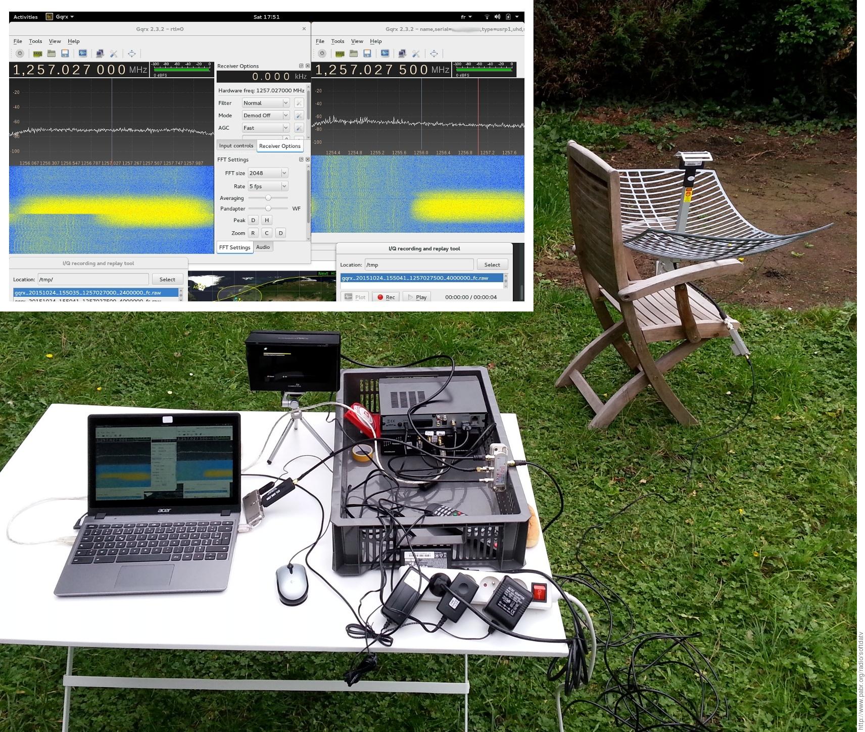
Over at www.pabr.org the author Pabr has been experimenting with using an RTL-SDR dongle for the reception of these digital amateur TV (DATV) signals. Over on Reddit he also posted some extra information about his work:

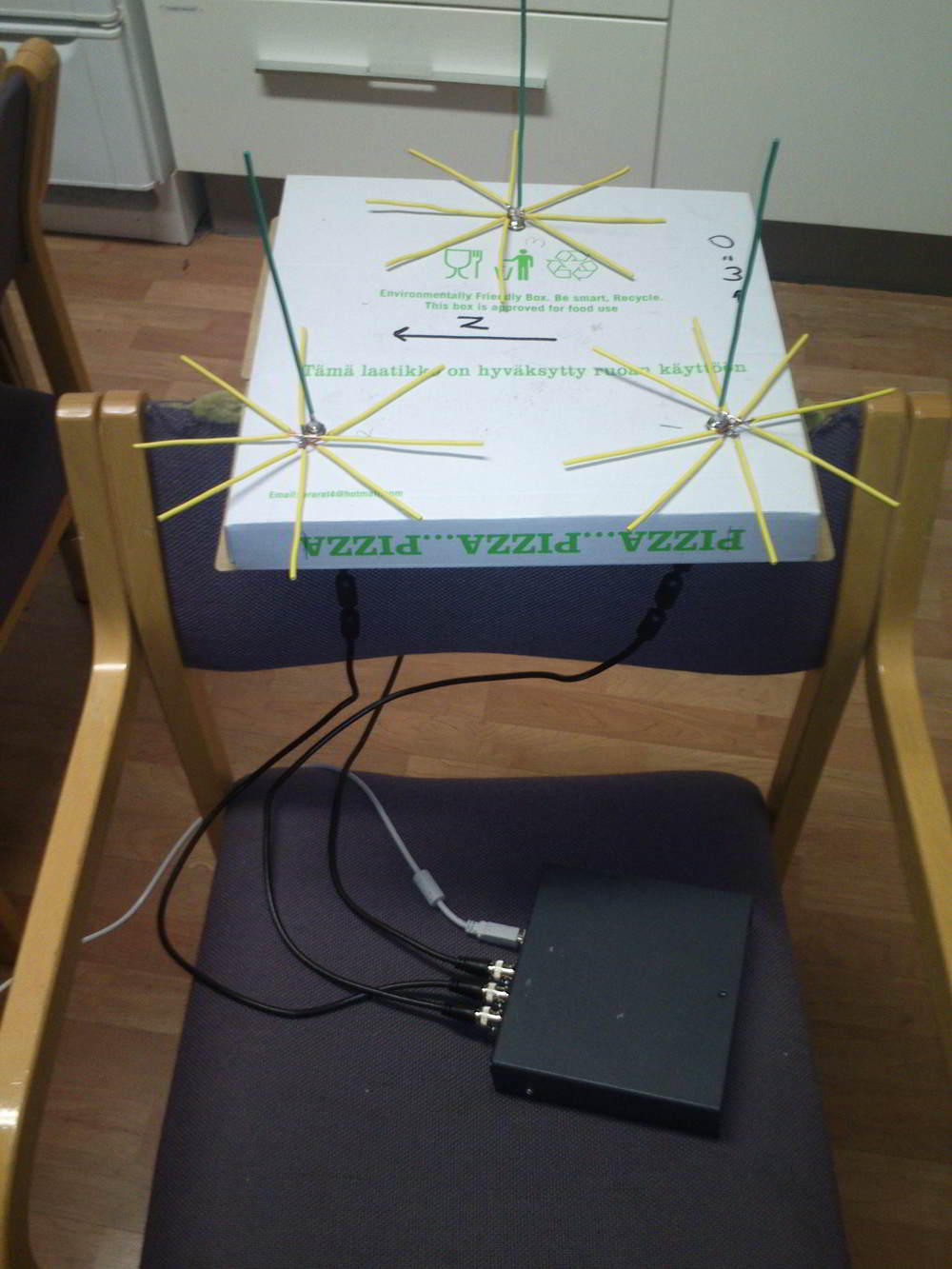
I have been able to receive DVB-S broadcasts from the ISS (known as HamVideo or HamTV) with a high-gain 2.4 GHz WiFi antenna ($50), a custom downconverter ($65), a R820T2 dongle, and a software demodulator (Edmund Tse’s gr-dvb). I used to think this could only be done with much more expensive SDR hardware.

It is commonly known that rtl-sdr dongles do not have enough bandwidth to capture mainstream satellite TV broadcasts, but the ISS happens to transmit DVB-S at only 2Msymbols/s in QPSK with FEC=1/2, which translates to 2 MHz of RF bandwidth (2.7 MHz including roll-off).

Before anyone gets too excited I should mention that:

  • This was done during a favourable pass of the ISS (elevation 85°)
  • With a fixed antenna, only a few seconds worth of signal can be captured
  • Demodulation is not real-time (on my low-end PC)
  • Currently the ISS only transmits a blank test pattern.

I now believe the BoM will be less than $50 by the time the ISS begins broadcasting interesting stuff on that channel.

Pabr uses a 2.4 GHz parabolic WiFi antenna to receive the signal. He writes that ideally a motorized antenna tracker would be used with this antenna to track the ISS through the sky. Also since the DATV signal is transmitted at around 2.4 GHz, a downconverter is required to convert the received frequency into one that is receivable with the RTL-SDR. The DATV decoder is available on Linux and requires GNU Radio.

Receiving DATV from the ISS
Receiving DATV from the ISS with an RTL-SDR

An RTL-SDR Phase Correlative Direction Finder

Over on YouTube user Tatu Peltola has uploaded a video showing his RTL-SDR based phase correlative direction finder in action. This set up uses three RTL-SDR dongles and three antennas to measure phase differences and thus determine the direction towards a signal source. All three RTL-SDR’s must be coherent, meaning that all three of their 28.8 MHz clock signals must come from the same source. 

In the video Tatu walks around the three antennas with a handheld radio. An arrow on a laptop screen points in the direction of the transmitter.

A known problem with RTL-SDR’s is that even with the clock sources synchronized there is still an unknown cause of additional phase shift. To solve this problem Tatu writes:

Each rtl-sdr is fed from the same reference clock to make their phase shift remain constant. They still have unknown phase shifts and sampling time differences relative to each other. This is calibrated by disconnecting them from antennas and connecting every receiver to the same noise source. Cross correlation of the noise gives their time and phase differences so that it can be corrected.

The three antennas used for direction finding.
RTL-SDR phase correlative direction finder

RTL-SDR Heat Dissipation as seen by a Thermal Camera

The RTL-SDR is known to get quite hot during operation and when it gets too hot reception of frequencies over 1.2 GHz can be degraded. Marko Cebokli wrote into us at RTL-SDR.com to show us some thermal imaging pictures that he has made of the RTL-SDR PCB. The images clearly show that the hottest part of the PCB is the R820T chip. The RTL2832U chip stays cool and the only other hot component on the PCB is the voltage regulator. In the post Marko also explains his conclusions on why the reception fails at frequencies over 1.2 GHz when it gets too hot.

The images show that the top of the R820T chip reaches a temperature of 85 degrees Celsius after just 10 minutes of operation. The underside of the chip reaches 68.9 degrees Celsius. Marko writes that these temperatures may be even higher when the RTL-SDR is placed inside the plastic case.

In general the RTL-SDR runs fine at these temperatures, but cooling the R820T chip will improve performance when tuning into signals that are higher than 1.2 GHz, for example with L-band satellites. Other RTL-SDR enthusiasts have cooled their RTL-SDR’s with thermal pads, heatsinks, fans and oil.

The RTL-SDR PCB seen with a thermal camera

Another L-Band Antenna Build and comparing L-Band reception on the RTL-SDR, HackRF and SDRplay

Over on Reddit user killmore231 has made a post showing his comparison of L-Band reception with RTL-SDR, HackRF and SDRplay software defined radios. killmore231 built the L-band patch antenna which Adam 9A4QV showed how to build on his YouTube channel late last month.

When testing the antenna on his RTL-SDR he saw no reception of any L-band signals at all. The RTL-SDR requires an external LNA to properly receive signals at this frequency range, which he did not have. Next he tried it on his HackRF and saw that some signals were weakly visible. When he tried it on his SDRplay the L-band satellite signals were clearly visible, probably due to the SDRplay’s good sensitivity at this frequency range and the fact that it has a built in LNA. His results show that the SDRplay is a good SDR for receiving L-band satellites as it does not need an external LNA for decent reception. An external LNA may still be needed if a long run of coax cable is used however.

SDRplay reception of L-band satellite signals with no external LNA.
L-band patch antenna

Passively Cooling the RTL-SDR with a Thermal Gap Pad

John Mills recently wrote in to us at RTL-SDR.com to show us how he cools his RTL-SDR by using a thermal gap pad stuck to the entire bottom of the RTL-SDR PCB. A thermal gap pad is a soft pliable material that is often used to interface between electronic chips and heatsinks. The gap pad forms into tight hard to reach spaces and conducts heat towards the heatsink. It is not electrically conductive, so the entire bottom of the RTL-SDR can be stuck to the thermal gap pad, which is then stuck to a metal heat sink.

John uses a thermal gap pad made by Bergquist, with part number GP5000S35-0.100-02. This gap pad is 0.1 inches thick, is easily cut with a craft knife and is tacky so it easily sticks to the heatsink and RTL-SDR PCB. It has a thermal conductivity of 5W/m.k. John uses the pad to help to cool the R820T, RTL2832U and voltage regulator chips. It has been shown in some previous posts that by cooling the R820T chip increased sensitivity can be obtained, especially at frequencies above 1.2 GHz.

He writes that if there is sufficient interest then he may consider selling strips of it on eBay. You can contact him at sdr_AT_milairuk.co.uk.

Below we’ve posted images of Johns thermal pad cooled RTL-SDR’s, along with his comments on them in the captions.

Inside latest SDR / Latest SDR - "This is my latest version using a R820T2 version, and I have also fitted this with a TCXO. In this version I also used a 1Mohm and 47nF to ground the USB shield wire as in a previous post. This version only uses one metal spacer and the end  of the PCB is secured by two M2 nylon screws / nuts. Case from China RF on Ebay."
Open SDR – “Just held onto a heatsink with two pieces of string ! Then this sits on another larger heatsink using another piece of Gap Pad to hold it – this has been working in my garden shed now for over 2 years feeding ADSB data”
Diecast Box SDR – "in this one I have made two small threaded metal clamps, lined with gap pad and tightened just enough to keep the PCB in good contact with the gap pad underneath and the diecast box. I use small BNC to MCX pigtails off Ebay to connect to the antenna socket. I also remove the LED and place through the box as can be seen."
Diecast Box SDR – “in this one I have made two small threaded metal clamps, lined with gap pad and tightened just enough to keep the PCB in good contact with the gap pad underneath and the diecast box. I use small BNC to MCX pigtails off Ebay to connect to the antenna socket. I also remove the LED and place through the box as can be seen.”
Inside latest SDR / Latest SDR - "This is my latest version using a R820T2 version, and I have also fitted this with a TCXO. In this version I also used a 1Mohm and 47nF to ground the USB shield wire as in a previous post. This version only uses one metal spacer and the end  of the PCB is secured by two M2 nylon screws / nuts. Case from China RF on Ebay."
Inside latest SDR / Latest SDR – “This is my latest version using a R820T2 version, and I have also fitted this with a TCXO. In this version I also used a 1Mohm and 47nF to ground the USB shield wire as in a previous post. This version only uses one metal spacer and the end of the PCB is secured by two M2 nylon screws / nuts. Case from China RF on Ebay.”
Latest SDR - Outside
Latest SDR – Outside

Comparing RTL-SDR’s on L-Band Reception, Tuner Temperatures and Passive Cooling

Over on Reddit user MaxWorm has been doing some experiments with comparing various RTL-SDR dongles on L-band (1 – 2 GHz) reception. Previously we wrote a tutorial on decoding Inmarsat signals which are at around 1.5 GHz and noted that the R802T/2 dongles can have some trouble at these frequencies.

It is known that the R820T/2 is not as good as the older now rare and expensive E4000 tuners at frequencies above 1.5 GHz, and it is also known that sensitivity decreases as the temperature of the R820T/2 increases, especially at frequencies above 1.5 GHz.

MaxWorm tested an R820T, R820T2 and two E4000 sticks at receiving L-band frequencies. He found that one of the E4000’s performed the best, but surprisingly the other E4000 dongle was totally deaf in the L-band. The R820T and R820T2 dongles performed similarly – not as good as the best E4000, but not as bad as the worst. All tuners exhibited reduced signal strength when warm.

In another post MaxWorm also measured the temperature of the tuner chips in each of his units, and created a simple heatsink for one of his R820T2 dongles. His results show that the heatsink passive cooling works well, significantly cooling the R820T2 chip. His measurements are copied below:

R820T2 in Plastic case:
R820T2: 77°C top / 74°C bottom
RTL2832: 56°C top / 54°C bottom

R820T2 bare PCB:
R820T2: 62°C top / 63°C bottom
RTL2832: 43°C top / 42°C bottom

R820T2 in Alu-Case with Alu “L-Bridge” on Tuner:
R820T2: top 37°C / bottom 47°C
RTL2832: top 49°C / bottom 40°C

E4000 in plastic case:
E4000: 37°C top / 37°C bottom
RTL2832: 46°C top / 40°C bottom

bare E4000 PCB:
E4000: 37°C top / 32°C bottom
RTL2832: 40°C top / 37°C bottom

Other experimenters have previously applied fan cooling and oil cooling to RTL-SDR dongles to cool them and increase sensitivity.

RTL-SDR with heat sink to aluminium case.
RTL-SDR with heat sink on the R820T2 chip connectoed to the aluminium case.
L-Band Reception Results for an R820T, R820T2 and two E4000 dongles.

SDR# updated to revision 1400 & SDR Touch updated to V2.6

The popular SDR# software which is often used together with RTL-SDR dongles has recently been updated to revision 1400. This new revision brings an interesting new feature which automatically estimates and displays the peak, floor and signal to noise ratio (SNR) values of the currently tuned bandwidth. Watching the SNR metric is very useful when tuning the RF gain settings, as best reception is obtained when the SNR value is maximised. The author also writes that there have been several radical changes to the code that leverage the latest .Net 4.6 framework which should improve the signal processing quality, CPU usage, user experience and hardware support. The changelog is pasted below:

Enhanced the Center tuning mode and extended it for RTL-SDR;
Enhanced the spectrum display;
Changed the frequency labelling to use multiples of 2.5/5/10 or frequency steps;
Added Peak, Floor and SNR estimation for the selection;
Enhanced the defaults for better user experience;

We note that some plugins may break with this update so be sure to make a backup if upgrading. Vasili, one of the most active SDR# plugin programmers has updated most of his plugins to work on this new version now.

Revision 1400 of SDR# with SNR estimation.

In addition to this update, over on the Android OS the popular mobile app SDRTouch has been updated to version 2.6. This new version brings the following features and improvements:

  • Baseband recording and file playback
  • Direct sampling support for full-band receivers
  • Improved SSB image rejection
  • Fixed tuning step
  • Manual filter bandwidth
  • Improved accessibility
  • Bug fixes

Reverse engineering a wireless thermostat with an RTL-SDR

When Tom Taylors home heating boiler was replaced the builders also replaced the old wired rotary thermostat with a digital wireless one. It sounds good, but Tom soon discovered that the thermostat UI was terrible and that the buttons were horrible to press, making him prefer to shiver in the cold. So Tom decided to see if there was a smarter way to control the heating.

When Tom investigated the thermostat, he discovered that the wireless unit transmitted in the unlicensed 433 MHz band and that the thermostat only transmitted two commands, turn on or turn off. By using his RTL-SDR and the CubicSDR software on his Mac he was able to detect the short blip of the thermostat wireless signal. Next he recorded the on and off signals and opened the sound files in Audacity, an audio processing software tool. In Audacity he was able to compare the sound waveforms of the on and off signals.

From his analysis he discovered that each signal consisted of a preamble and then an on or off command which is repeated twice, presumably to reduce the likelihood of interference. Tom also discovered that the commands were encoded with pulse width modulation.

From this knowledge Tom was then able to use a cheap 433 MHz transmitter together with an Arduino microcontroller board and a short script to create identical on or off transmissions that control the boiler. Tom writes that his next steps are now to create a heating schedule based on his families shared calender, make a thermostat control loop and create a web connected interface with a Raspberry Pi.

The 433 MHz thermostat on/off signal detected with an RTL-SDR in the CubicSDR software