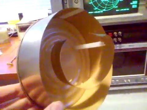
Over on YouTube user Adam Alicajic (creator of the popular LNA4ALL low noise amplifier) has uploaded a video showing the performance of a home made wideband helix antenna that he has created for receiving signals such as ones from L-Band Inmarsat satellites. See our tutorial for more information on receiving Inmarsat signals.
Adams helix antenna is built out of an old used can and is based on a 1.1 turn design. In the first of three videos he shows that the SWR of the antenna is all well below 2.0 from 1.5 GHz to 3 GHz. In the second video Adam shows the performance of the helix antenna on actual L-band signals being received with an RTL-SDR dongle. In the final video Adam compares the helix again a patch antenna and finds that the two receive with very similar performance.
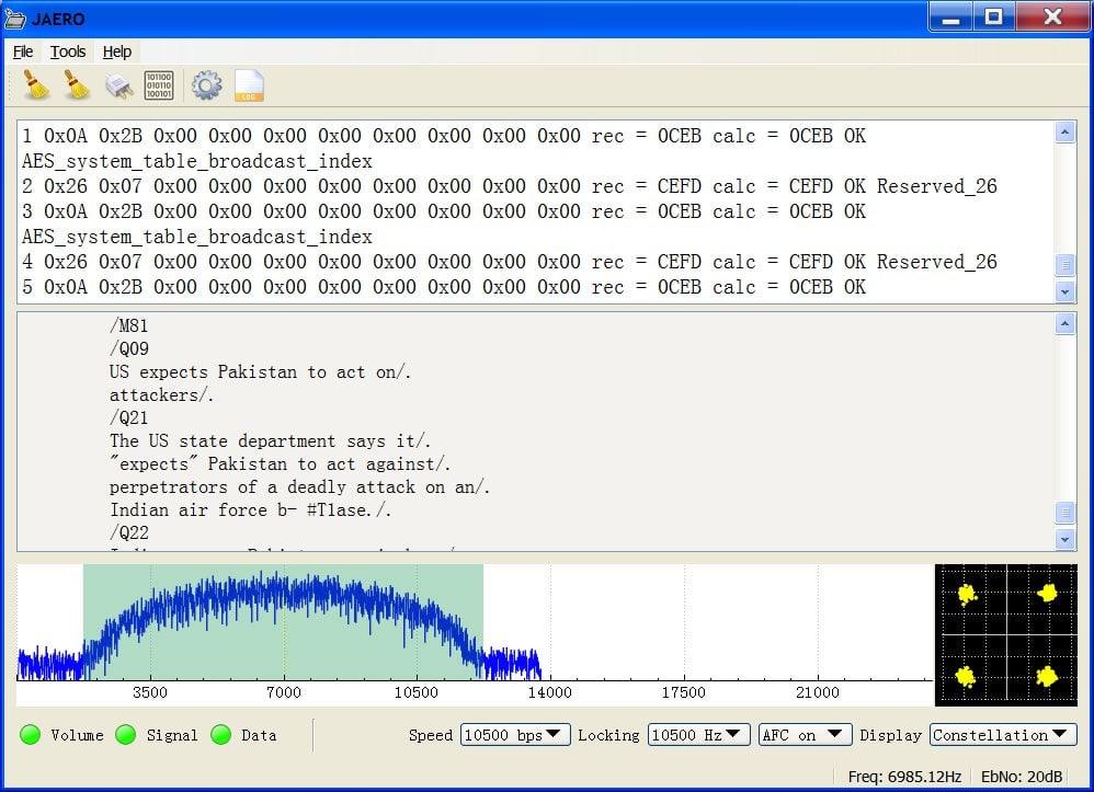
Over on YouTube Adam Alicajic (9A4QV – creator of the LNA4ALL and upcoming MIX4ALL) has uploaded a video showing his reception of AERO-H signals from an Inmarsat satellite. A few days ago we posted about how the JAERO decoder had recently been updated to be able to decode these AERO-H signals. These signals contain various messages meant for airplanes, but also sometimes contain news messages.
In the video Adam uses a satellite dish antenna together with his MIX4ALL, an RTL-SDR dongle and the JAERO software. With decent reception he is able to easily decode the AERO-H messages.
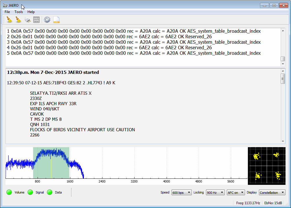
The JAERO decoder for AERO signals on Inmarsat satellites has recently been updated to version 1.03. This new version supports the decoding of 10.5k Aero-H and Aero-H+ signals. The author of JAERO Jonti writes that on these channels he’s seeing significantly more traffic than on the narrowband signals and that he was suprised to see that other non-aircraft messages such news was broadcast on this 10.5k signal. Jonti writes about his experience in developing the 10.5k decoder and his experience with receiving the messages in this post.
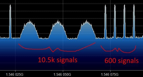
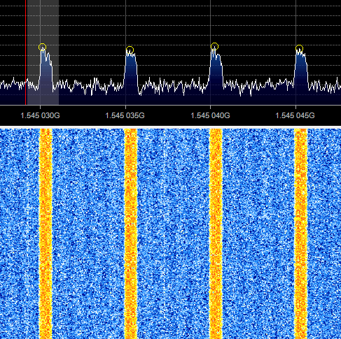
Jonti discovered that news updates are also broadcast on 10.5k AERO.What the 10.5k signals look like compared to the 600 signals.
If you like Jonti’s apps, then please remember to donate a small amount to him so that he can continue to work on them more. His PayPal donate button can be at the bottom of his main page.
Over on YouTube user Adam Alicajic has recently been uploading videos that show him testing a prototype of his upcoming product the MIX4ALL. The MIX4ALL is an RF downconverter which will allow the RTL-SDR to receive signals at around 1.5 GHz or higher. Although the RTL-SDR can already tune up to ~1.7 GHz, above about 1.2 GHz sensitivity is poor and some units have problems receiving when they get hot. The downconverter will convert a 1.5 GHz signal into a signal at around 250 MHz, where the RTL-SDR operates well. At around 1.5 GHz there are several satellite signals of interest including Inmarsat EGC, Iridium and AERO signals.
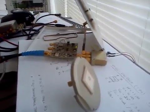
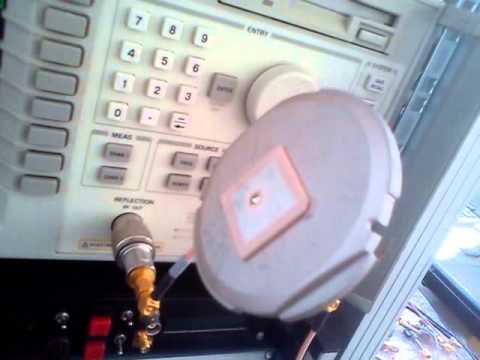
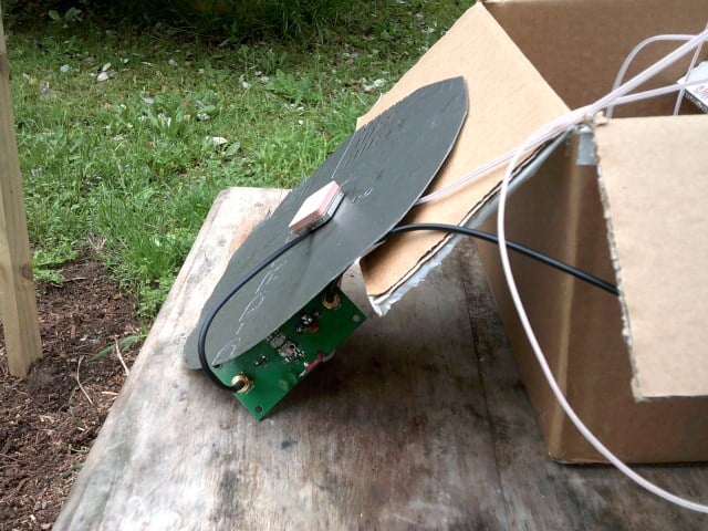
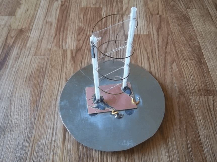
On one video Adam decided to use the MIX4ALL to test the difference between a GPS patch antenna and a home made air gap patch antenna. The GPS patch antenna was salvaged from an old GPS receiver and the patch antenna is the one discussed in this previous post. In the test Adam used the MIX4ALL and an RTL-SDR, and tested reception of Inmarsat signals. His results showed that the reception given by the GPS patch was very poor compared to the home made patch antenna.
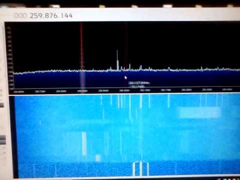
Comparing the GPS and DIY Patch antenna for the L-band INMARSAT
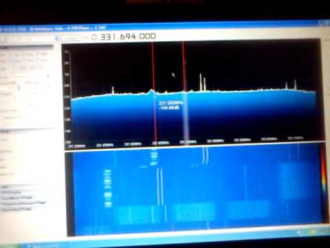
GPS antenna match on L-band 1575 MHz
Some other recent videos by Adam show him also testing his MIX4ALL with S-Band signals around 2.3 GHz and also receiving Alphasat XL.
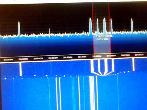
MIX4ALL receiving on S-band terestrial weak signals
Alphasat XL band spectrum using the converter and R820T dongle
Adam (9a4QV) is well known in the RTL-SDR community for creating and selling the LNA4ALL low noise amplifier and several filter circuits as well. Now Adam has uploaded on his YouTube channel a new video that shows a prototype of his latest upcoming RTL-SDR compatible product called the MIX4ALL. The MIX4ALL is a downconverter that will improve the ability of the RTL-SDR to receive satellite signals in the L-band which are usually at around 1.5 GHz.
It is known that the most common R820T/2 RTL-SDR’s are not very sensitive at 1.5 GHz, and some can even stop receiving properly at this frequency when they get too hot. A downconverter will simply convert the 1.5 GHz signals into a lower frequency which can be received much better by the RTL-SDR.
In the first video Adam shows the MIX4ALL being used with an RTL-SDR to receive various Inmarsat signals with a patch antenna. In the second video he shows reception of AERO-I signals.
Adam writes that he expects to be able to sell the MIX4ALL near the end of January 2016.
Back in August of this year we showed how it was possible to use an RTL-SDR dongle, satellite antenna, LNA and decoding software to receive and decode STD-C EGC signals from Inmarsat satellites. We also showed how it was possible to modify a low cost GPS antenna to use as a satellite antenna.
Now a radio hobbyist called Jonti has released a Windows decoder for the Inmarsat AERO set of signals. AERO is a system that provides a satellite based version of VHF ACARS (Aircraft Communications Addressing and Reporting System). ACARS is typically used by ground control and pilots to send short messages and is also sometimes used for telemetry.
Jonti writes:
JAERO is a program that demodulates and decodes Classic Aero ACARS (Aircraft Communications Addressing and Reporting System) messages sent from satellites to Aeroplanes (SatCom ACARS) commonly used when Aeroplanes are beyond VHF range. Demodulation is performed using the soundcard. Such signals are typically around 1.5Ghz and can be received with a simple low gain antenna that can be home brewed in a few hours in conjunction with a cheap RTL-SDR dongle.
In the advent of MH370, Classic Aero has become a well-known name. A quick search on the net using “Classic Aero MH370” will produce thousands of results. The Classic Aero signals sent from satellites to the Aeroplanes are what JAERO demodulates and decodes.
Unlike the usual VHF ACARS, with SatCom ACARS you can not receive signals from the Aeroplane only the people on the ground talking to the people in the Aeroplane. This means you do not get the airplanes reporting their position. Instead you tend to get weather reports, flight plans, and that sort of stuff. Just like VHF ACARS they usually use cryptic shorthand notation. For example “METAR YSSY 040400Z 08012KT 9999 FEW040 SCT048 23/09 Q1024 FM0500 05012KT CAVOK=” is the weather report for Sydney Airport in Australia in a format called METAR. It tells you the time, when the report was issued, the wind direction and speed, visibility, clouds, temperature, due point and air pressure. Then it says from 5 AM UTC the wind direction and speed and that the weather will be nice. There are sites such as Flight Utilities that can decode such information and display it in a more understandable format.
In his post Jonti also shows how he uses a modified GPS antenna to receive the AERO signals.
Jonti’s modified GPS antenna for receiving Inmarsat AERO
We gave JAERO a test and found that it decoded AERO signals easily, even with low signal strength. To use JAERO tune to an Inmarsat AERO signal in SDR# or a similar program using USB mode. JAERO will listen to the audio from the sound card or from a virtual audio pipe. We recommend setting the AFC (Automatic Frequency Control) setting on on if you find that your RTL-SDR drifts too much.
AERO signals can be found at around 1545 MHz. They only use about 800 Hz in bandwidth. See UHF satcoms page for a list of AERO frequencies.
The JAERO decoder.Some AERO signals.
Remember that some R820T/2 RTL-SDR dongles can have problems when receiving this high, especially when they heat up. If you find that your dongle gets deaf at these L-band frequencies try cooling the R820T/2 chip with a heatsink or fan. The Airspy or SDRplay RSP software defined radios are better choices for decoding signals this high, but the RTL-SDR will work fine if your signal strength is decent and the R820T/2 chip is kept cool.
If you are interested in VHF ACARS as well, then we have a tutorial about decoding that here.
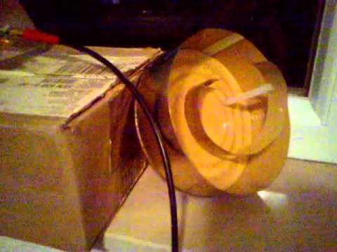
Previously in August of this year we wrote an article showing how to decode Inmarsat satellite STD-C NCS EGC messages with an RTL-SDR. Inspired by this article, RTL-SDR.com reader Mario Filippi, N2HUN has written in to show us how he built an L-band helical antenna to receive these signals. A helical antenna is one of the better choices for receiving Inmarsat signals as it will provide higher gain when compared to a patch antenna, however the disadvantage is that it is much larger. Of related interest, Adam 9A4QV also recently showed us a video detailing the correct dimensions for building an air gap patch antenna.
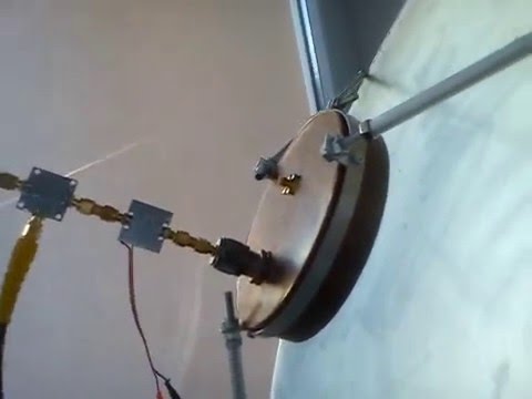
Mario’s Inmarsat antenna consists of a 90cm Ku band dish, a homebrew L-band LHCP helical antenna and an inline amplifier. He used the assembly instructions found on UHF Satcom’s page at http://www.uhf-satcom.com/lband and scavenged most of the parts from his junk box. To help others with the construction of a similar antenna Mario has also created a document detailing the construction of the antenna with several useful build images (.docx file).
Helical Inmarsat antenna feed for a 90cm Ku band dish
Mario has also recently given a presentation about the RTL-SDR to the Mid Atlantic States VHF Conference entitled “SDR Dongle for VHF/UHF Reception”. The presentation is an overview of the RTL-SDR dongle and many of its interesting applications, including several screenshots of software in action (dropbox) (mega mirror).
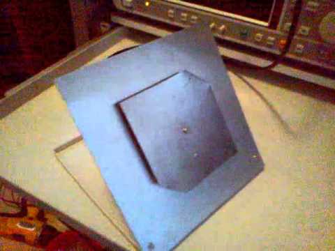
Over on YouTube Adam 9A4QAV (creator of the LNA4ALL and other RTL-SDR related products) has uploaded two videos showing his home made L-band patch antenna in action receiving Inmarsat-C and in the second video describing the construction of the antenna. Inmarsat is a geostationary satellite service that provides services such as satellite phone communications, broadband internet, and short text and data messaging services. Some of the messages on the Inmarsat STD-C NCS EGC channel are marine safety messages that are decodable with an RTL-SDR. This was discussed in our tutorial that we posted back in August. In that tutorial we used a prototype patch antenna that was supplied by Outernet.
Adam’s home made L-band patch antenna consists of two thin sheets of conductive metal, cut to the right dimensions which are described in the second video. We have recorded the dimensions here (though be sure to double check with the video for correctness):
Reflector Size: 170 mm x 170 mm Patch Size: 98 mm x 98 mm Corner Trim: 21 mm from top right and bottom left corners Coax Connection (Probe): 25 mm from bottom edge Height of patch from reflector: 7 mm
The corners of the patch need to be trimmed to give the patch antenna right hand circular polarization (RHCP), which is the polarization used by Inmarsat Satellites.
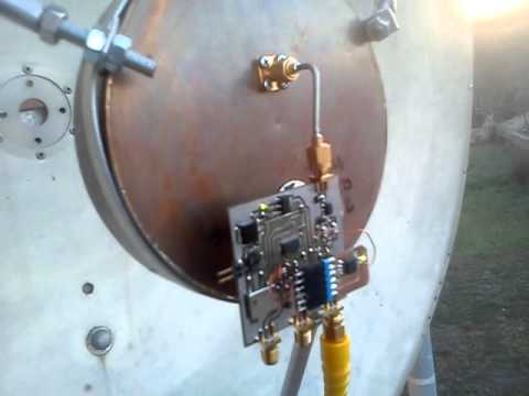
The first video shows the patch in action with Inmarsat-C being received. In this video he also uses a simple downconverter to shift the 1.5 GHz Inmarsat-C frequency down to 300 MHz, which avoids the problem of the RTL-SDR not working very well at 1.5 GHz and above. In the second video Adam explains the dimensions of the antenna.
Inmarsat-C reception - Patch antenna & d/converter conv gain 30db