Testing out the New Airspy HF+ Preselector
The Airspy team have recently been working on a preselector retrofit product for their HF+. The Airspy HF+ already has excellent dynamic range and sensitivity, but by adding a preselector they seek to improve performance enough to claim that the HF+ is as good as or even better than much more pricey SDRs like the Perseus by achieving dynamic range figures of more than 105 dBm.
A preselector is a filter or bank of filters that attenuates out of band signals. This is useful as radios can desensitize if an unwanted signal comes in too strongly. For example, if you are tuned to the 20m band, but there is a very strong MW signal, the SNR of your desired 20m band signal might be reduced. Radios with a natural high dynamic range design like the Airspy HF+ are less affected by this problem, but for the strongest of signals use of a preselector can still help.
The Airspy HF+ preselector needs to be soldered directly onto the HF+'s PCB, and once installed it automatically switches bands using GPIO expansion ports controlled automatically via tuning in SDR#, so no external switching is required.
The expected pricing of the HF+ preselector is US$49, and it will be ready for sale in a few weeks.
Measurements
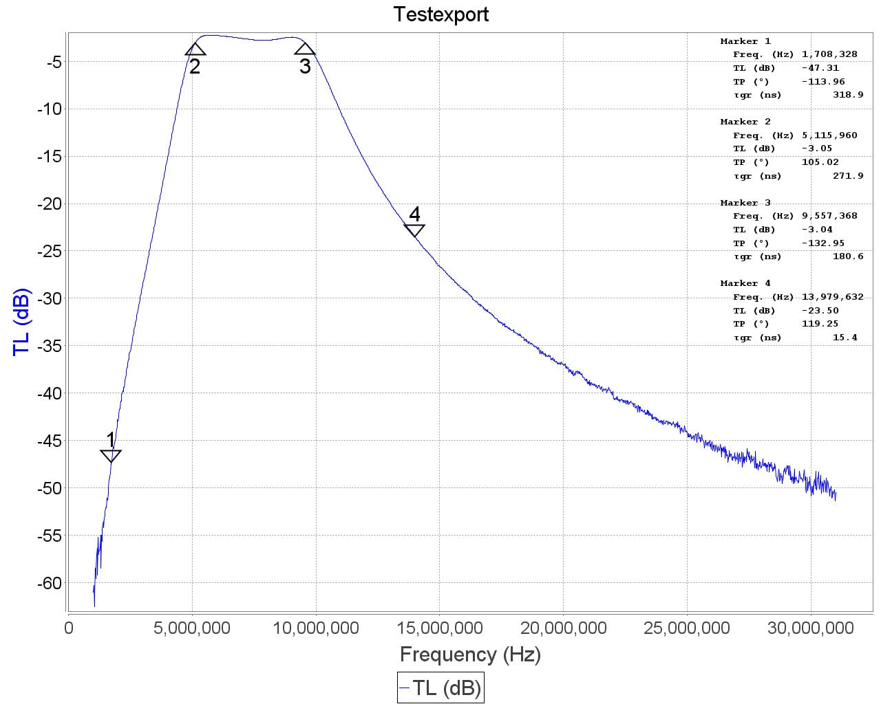
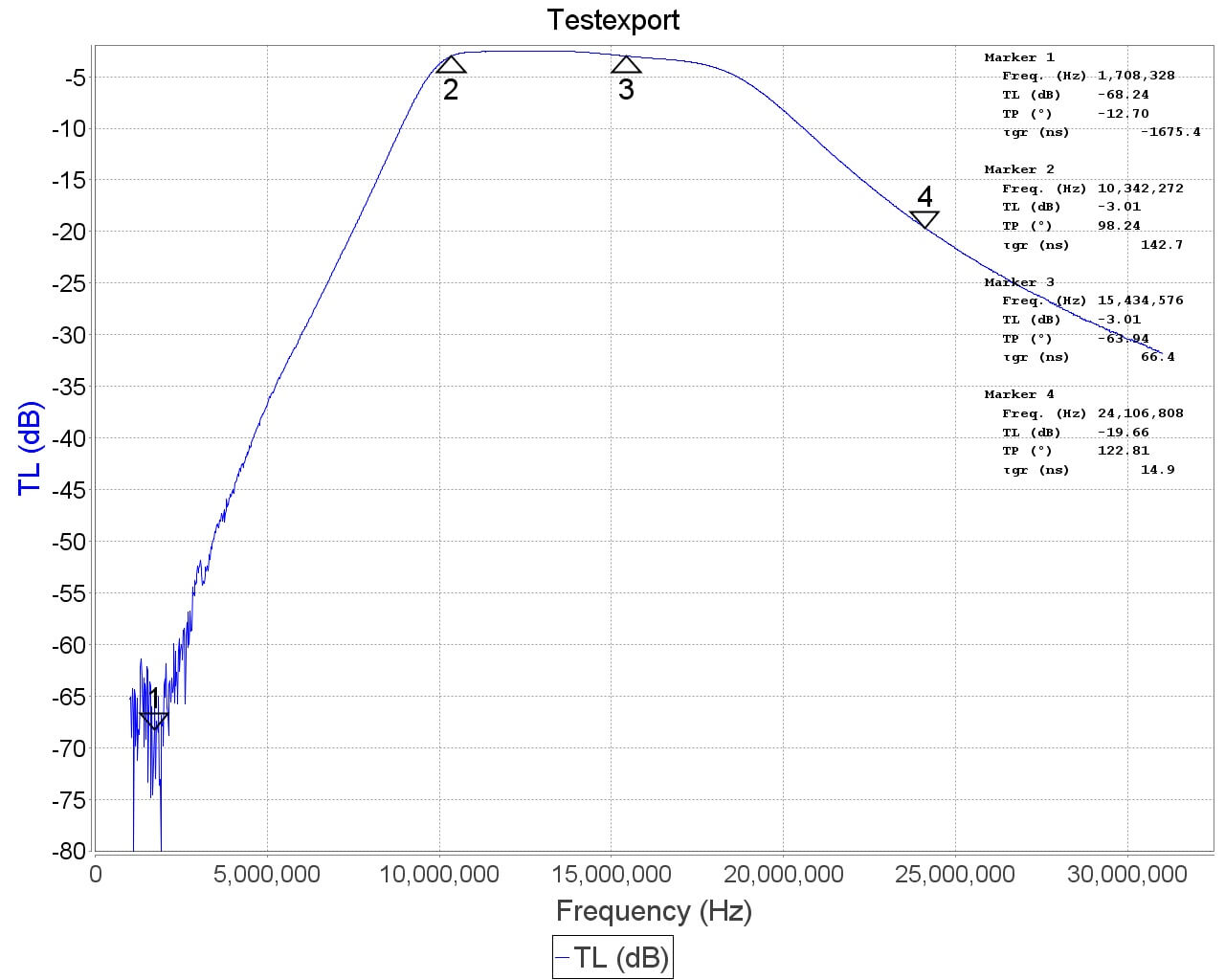
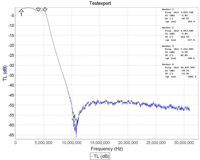
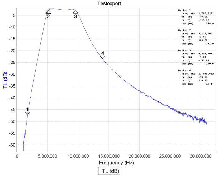
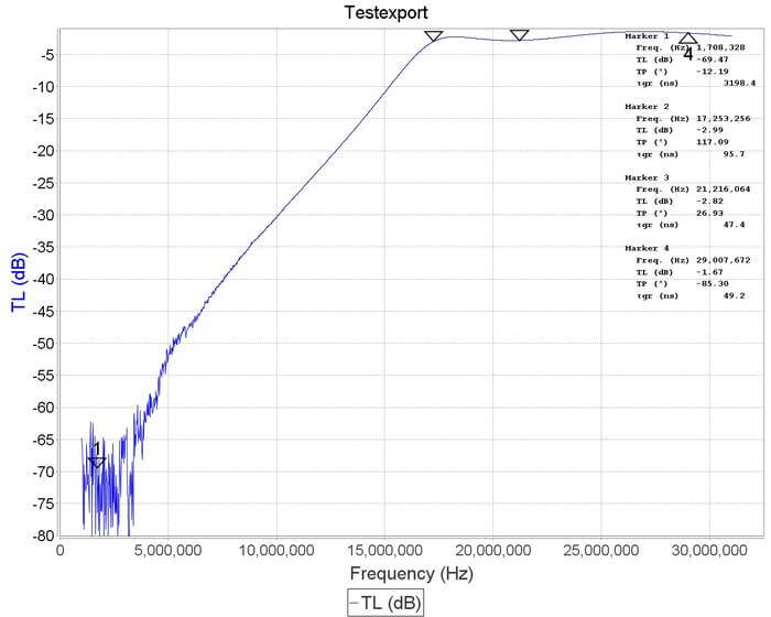
We received a prototype of the filter a few days ago and have been testing it out. From measurements on a VNA, we found that the preselector features four bands of operation:
- 0 - 5.2 MHz
- 5.2 - 10 MHz
- 10 - 17 MHz
- 17 - 30 MHz
Airspy have also provided us with a block diagram schematic which we show below.
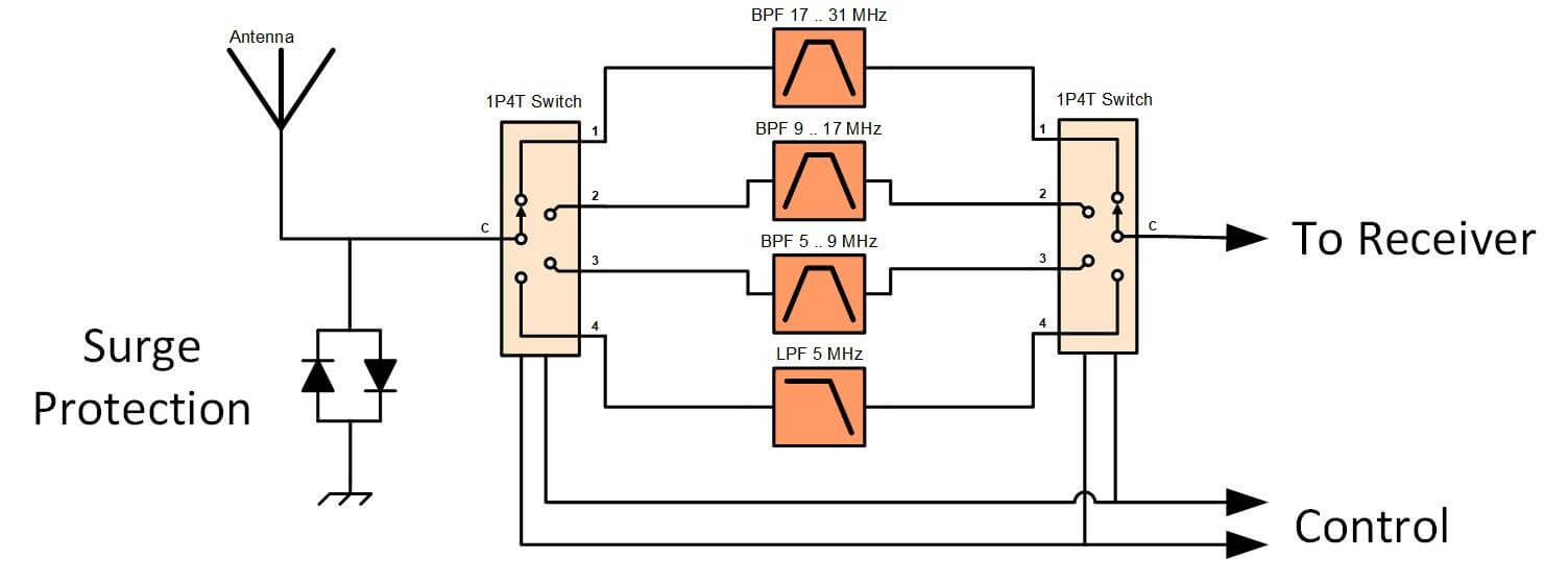
Insertion loss appears to be mostly below 3 dB with fairly steep skirts especially on the lower side. The top three filters do an excellent job at blocking out the broadcast AM band. Below are some VNA plots that show the filter responses.


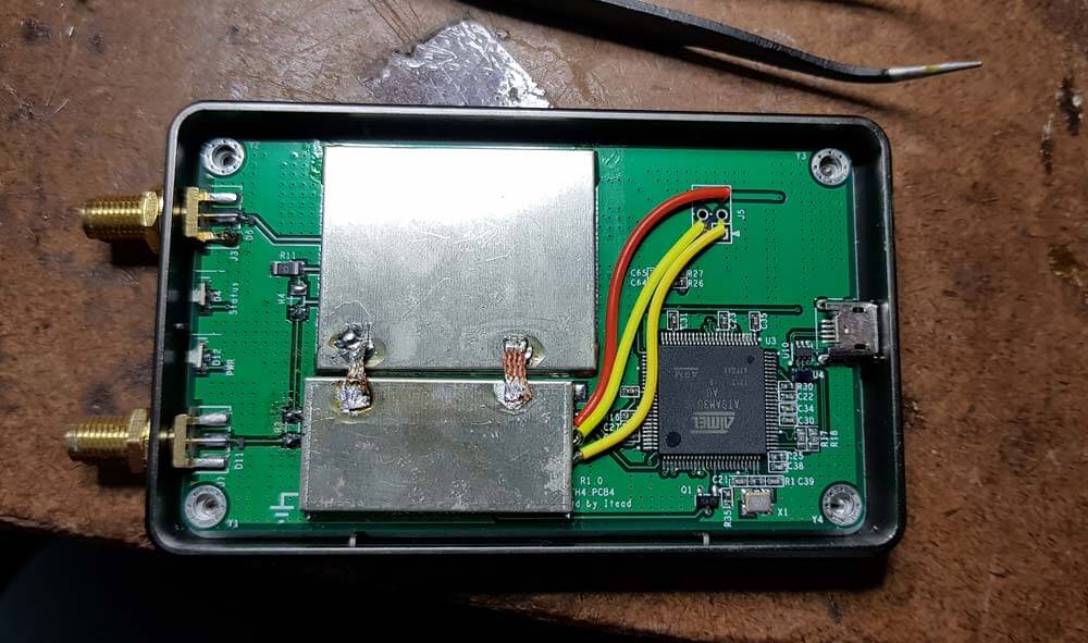
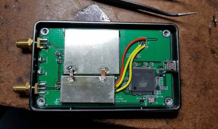
Installation
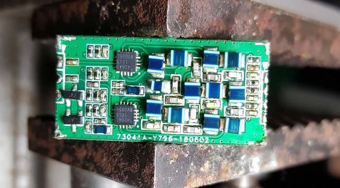
The preselector comes in a small 3.2 x 1.7 cm sized PCB that is fully covered with a metal shielding can. To install it you need to carefully solder it onto the HF+ PCB. This can be a little tricky since the pads are so small, but if you're experienced with soldering it shouldn't be an issue.
- First you need to open the HF+ and remove R3 from the HF+ PCB, which is a zero ohm resistor.
- The preselector PCB can then be positioned and the two IN and OUT pads soldered in place.
- Then you'll also need to connect the power and 2x GPIO lines to the preselector using wires.
- Now you need to bridge the two shielding CANs with a thick bit of wire. We simply used two cuts of copper solder braid to do this.
- Finally is also recommended to update the HF+ firmware to the latest version and download the latest version of SDR#.
Once soldered in place the preselector is ready to use, and the HF+ cover can be put back on. It is expected that the commercially sold versions of the preselector will come with detailed installation instructions.
In the first photo below we removed the shield to see what was inside, and the second photo shows it installed on the HF+ PCB.

Using it on a RTL-SDR V3
Whilst the preselector is designed for the Airspy HF+, there's no reason why it couldn't also be retrofitted onto other SDRs, such as our RTL-SDR V3, for use in improving direct sampling mode performance.
The V3 has spare GPIO ports that can be used to control the filter, and 5V for powering the filter could be tapped off the PCB as well. Currently we're considering making a breakout PCB for the filter than might aide with this.
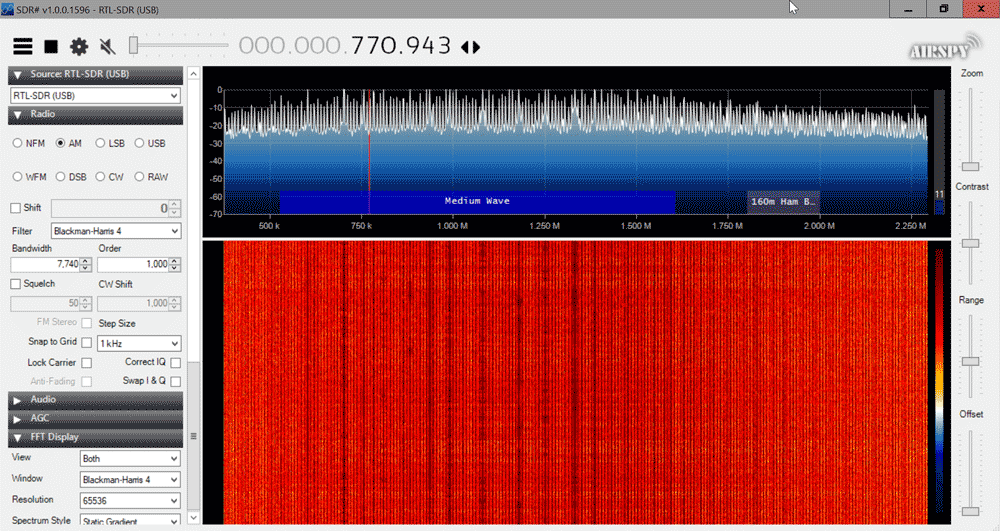
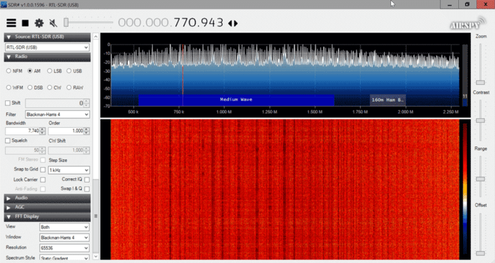
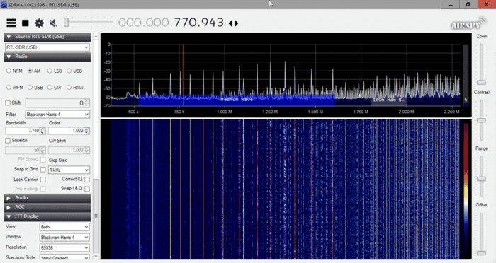
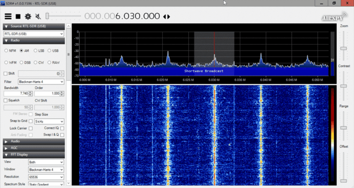
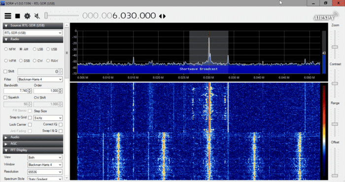
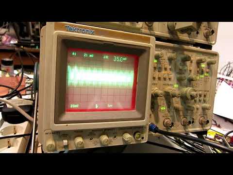
We did a quick test with the preselector connected to the RTL-SDR V3 running in direct sampling mode, and as expected performance is much better, especially above 5 MHz once the second filter kicks in. This is because the second, third and fourth filters all heavily attenuate the MW broadcast AM band, which is the main source of overload issues on HF.
The following screenshots show how much the filter was able to reduce the signal strength of AM broadcast when the second 5.2 - 10 MHz filter was turned on. This reduction was enough to prevent overload on all the higher bands.


HF+ Results
For the HF+ we tested by injecting a strong signal into two HF+ SDRs, one with the filter installed and the other without. The HF+ with the filter was routinely able to withstand much higher signal powers without any signs of overload occurring, and no degradation due to insertion loss was observed.
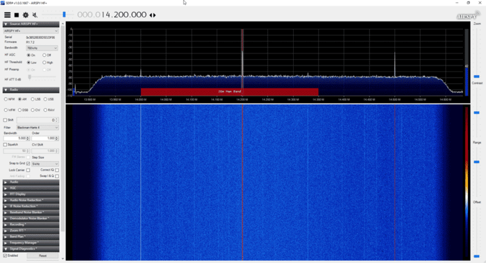
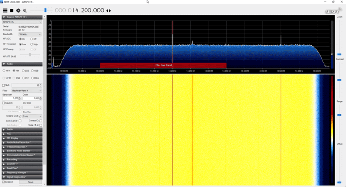
The screenshots below show an experiment with a weak desired signal injected at 14.2 MHz, and a strong unwanted signal being injected at 1.5 MHz. With the unwanted signal at 5 dBm, the filtered HF+ showed no signs of overload, whilst the unfiltered HF+ had the AGC kick in to increase the front end attenuation, reducing the signal strength by about 20 dB and raising the noise floor.


Other Reviews
Other reviewers have also received the preselector and have been testing it. Fenu radio has uploaded a short review, and plans to write more in the future. He's also made his HF+ with preselector available for public use via SpyServer (details in his post). In the video below Leif SM5BSZ reviews the preselector and runs through several tests while comparing it against the Perseus. His results seem to show that the Persues gets a +25 dBm IP3, whilst the HF+ with the latest firmware and preselector is able to obtain a respectable +10 dBm IP3.
Conclusion
For most people, the dynamic range of the HF+ is probably already more than enough, but if you are receiving very strong signals, the preselector can help get you get more performance out of the HF+. Of course the preselector cannot help if you have strong signals within the filter bands.
If you're looking to get the most out of your HF+ then the filter at only $49 is a pretty good deal. Just take note that you'll need to open the HF+ and be comfortable with soldering onto the PCB.


Beautiful – but it all makes no sense unless we get any idea if, when or where we can get it.
Exactly… would love to get one however they have not answered any emails I have sent asking for info.
I would like to know what ever happened to Airspy hf + pre-selector ???? Is it out for sale and if so were can I buy it ?????
The last mention I could find was at the bottom of this tweet from three months ago – https://twitter.com/lambdaprog/status/1045656859829587968
A standard preselector with many more steps ist the better way – outside…low price…
$49 isn’t a bad price – you forgot to add recovery of development costs to bring it to manufacture and the fact that it isn’t going to sell in tens of thousand units, so the overheads per unit will be much higher than most typical ‘consumer’ items.
However, I suspect that most HF+ users are unlikely to have a good enough antenna to warrant it as a standard fit. You really need to have a substantial antenna system to make full use of the existing HF+ dynamic range and only require additional filtering in a few specific cases such as a nearby BC transmitter.
Tell them Timmy-prog!
I’m not a programmer if that is what you mean ?
I’ve nothing to do with the product, but I do like knowing how hardware works (and how to bring a functioning product to market, without going bust), so I may study printed circuit board pornography a bit more than most.
With a 1000% recharge over the bill of materials + assembly we can easily undestand why this cm. 3×1.5 filter bank, essential in any respectable SDR receiver, was not inserted in the main pcb.
Looking at the above image I’m seeing components that look like what I’m tallied up the price for below using mouser/digikey, I’m guessing most of the components so take everything with a grain of salt.
Nice thick layer of cream:
~52x 20% tolerance passive components: ~14 inductors, ~27 capacitors, ~11 resistors
inductors ~4 cents each ($0.56 for 14)
capacitors ~3 cents each ($0.81 for 27)
resistors ~ 1 cents each ($0.11 for 11)
Thick layer of cream:
~52x 1% tolerance passive components: ~14 inductors, ~27 capacitors, ~11 resistors
inductors ~15 cents each ($2.1 for 14)
capacitors ~2 cents each ($0.54 for 27)
resistors ~0.3 cents each ($0.04 for 11)
Going bust:
~52x 0.1% tolerance passive components: ~14 inductors, ~27 capacitors, ~11 resistors
inductors ~50 cents each ($7 for 14)
capacitors ~25 cents each ($6.75 for 27)
resistors ~6 cents each ($0.66 for 11)
2x pe42641 SP4T RF switch ~$1 each
2x ?TVS diodes? ~2 cents each
1x PCB $1 maybe $2 – the PCB is small and looks like a two sided PCB with vias.
1x EMI metal shielding ~$1
assembly and testing $1 to $2 each
Typically you multiply the BOM by 3 to get the approximate price, because there is usually a 30% profit margin to creators and a 30-40% profit margin to the distributors.
If they are using 0.1% components, which is total overkill, the numbers look like they would be out of business soon.
If they are using 1% passives, they are probably making an extra $20 on each sale, which they will need to help cover people who, think they can install the board but can’t and, destroy their HF+.
If they are using 20% tolerance components. That would be a BOM of ~$7.5 and an extra $27 cream on top of the usual profit margins.
I’m not seeing 10x profit margins, but maybe my maths is not as good as yours. Oh and all of the above prices assumed that you were buying components in bulk, shipments of 10k each, so if you were making a one off, you could not make it that cheap, you would pay over $50 to make your own board.
Hi Everybody .
I live 11.5 miles from downtown Pensacola and I have a HF+ , the only out of band signals I saw was at 160 meters . That was fixed when Airspy released new Firmware last month . Now when I was using the V3 dongle I would have broadcast AM and FM band all over the place . So I got a MFJ 1020 C and it took care of two problems that you would have with direct sampling , out of band signals and no gain control . Would someone be so kind out their to tell me if their is gain control on the HF+ in the VHF mode .
Did you look at Fig.6 and Fig.7 of the data sheet?
The plotted lines do not stop at 0.1 GHz and don’t show significant increase of attenuation below 0.1 MHz so the insertion loss is somewhere between 0.35 dB to 0.5 dB.
Yes, i have seen that but your conclusion gives for granted that they gave a 100 MHz lower limit for no reason. In this case an important disclaimer is missing in the datasheet: “The manufactuter reserves the right to give misleading informations as the reader is supposed to have the knowledge to recognize them”
Part of the insertion loss is caused from the RF switch PE42641.
According to the datasheet it has a frequency range rated 100MHz- 3.0GHz but the datasheet does not show and reason for the 100 MHz lower limit mentioned only in the product’s specifications subtitle.
Usually what is specified as an operating range in a datasheet is what the company who created the part will test and guarantee correct operation during production. There is nothing stopping any company from buying the parts and retesting that they function correctly in the frequency range that they will use in a final product which could be totally outside the specification guaranteed by the part manufacturer. Calibrated test equipment that tests from DC to 3 GHz is more expensive (especially in terms of time) than that which only tests from 100 MHz to 3 GHz. And since their primary market is GSM, WCDMA, and wireless applications up to 3000 MHz, It is cheaper (especially in terms production run testing time) not to validate correct operation below 100 MHz which will only ever account for a tiny fraction of a percentage of their final sales.
That sounds reasonable Timmy!