PiTX works by modulating the GPIO pins on the Pi in such a way that it is able to produce FM modulation. The major problem with using this method of producing radio is that it creates large amounts of harmonics and interference outside of the intended transmit frequency. Interference like this is illegal and could potentially disrupt life critical radio systems such as emergency services, cellphones and air traffic control.
In order to cleanly transmit with PiTX an output RF filter should be used. Recently, the team over at TAPR.org have released a 20M WSPR TX filter shield. WSPR is pronounced “Whisper” and is short for “Weak Signal Propagation Reporter Network“. It is a type of amateur radio signal that can be broadcast and received around the world by using very low transmit power. Radio amateurs use it to see how far their signal can travel when using very low power (QRP) and to investigate signal propagation conditions.
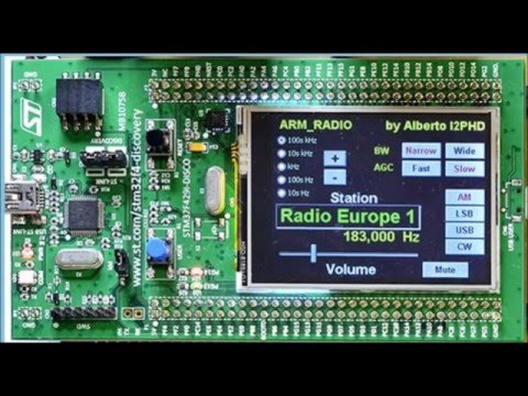
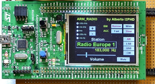
Back in November 2015 we posted about the ARM Radio, a minimalist direct sampling software defined radio that runs almost entirely on an ARM processor on a STM32F429 discovery board. It can tune from about 8 kHz up to 900 kHz, which covers the VLF, LF and some of the MF bands.
Now over on YouTube amateur radio hobbyist W9RAN has uploaded a video where he demonstrates an ARM Radio that he built. He shows the radio in operation with it clearly receiving some NDB’s and some AM broadcast stations.
I walked out to my car from Bunnings, and there was a new HSW Maloo parked in front of me with the owner staring at his key fob and shaking his head.
I said “let me guess, car won’t open?” and he said yeah, and he’d been trying for about 5 minutes. I said that I’d had the same thing happen to me a few months back in the same spot, and then went to open my car.
Nothing. No beep, door stayed locked. Looked around and there was another couple trying to get into their car as well (late model C Class).
It took about 5 minutes of me trying the door every 20 seconds or so before it opened. HSV owner was still there when I left. The only thing he and I could think of causing it was the mobile phone tower in front of Aldi.
After reading the post, user u/riumplus decided to go out to the same spot with his Funcube dongle SDR and see if there was any interference that might explain the issues. But he found no such interference. However, when he pressed the wireless entry on his own keyfob he noticed reflections from the main transmission that were coming from the buildings walls. He wrote:
Cyberspectrum is a monthly software defined radio meetup that is held in San Francisco. During this meetup presenters show and discuss their SDR related work. The 12th Cyberspectrum meetup is occurring right now and this time there will be presentations from amateur radio astronomer Marcus Leech from Canada and wireless security researcher Tobias Zillner from Austria.
There is a live stream on YouTube shown below, and after it finishes it will also be available for viewing:
Edit: Stream is over. Marcus Leech gave a nice talk that gave an overview or amateur radio astronomy and explained some of his set up where he uses RTL-SDR dongles as the receiver.
Cyberspectrum: Bay Area Software Defined Radio #12 (Dec 2015)
The overview of today’s presentations are as follows:
• Marcus Leech from SBRAC: “An integrated proof-of-concept ‘all-digital’ feed for 21cm radio astronomy”
We show ongoing work in designing and building a proof-of-concept ‘all digital’ feed for 21cm radio astronomy experiments. While many professional radio astronomy observatories are using “digitize at the feed” techniques, amateur experiments (and successes) in this are very close to non-existent.
Digitizing at the feed carries many advantages, including overall system gain stability, and the ability to carry signals over cheap ethernet-over-fiber links.
We’ll show an example feed arrangement that uses a differential radiometry approach, and does much of the initial processing right at the feed, including radiometry and spectral calculations, sending summary data to an ordinary PC host over ethernet.
Challenges and pitfalls will be discussed.
• Tobias Zillner from Cognosec: “ZigBee Smart Homes – A Hacker’s Open House”
ZigBee is one of the most widespread communication standards used in the Internet of Things and especially in the area of smart homes. If you have for example a smart light bulb at home, the chance is very high that you are actually using ZigBee by yourself. Popular lighting applications such as Philips Hue or Osram Lightify and also popular smart home systems such as SmartThings or Googles OnHub are based on ZigBee. New IoT devices have often very limited processing and energy resources. Therefore they are not capable of implementing well-known communication standards like Wifi. ZigBee is an open, public available alternative that enables wireless communication for such limited devices.
ZigBee provides also security services for key establishment, key transport, frame protection and device management that are based on established cryptographic algorithms. So a ZigBee home automation network with applied security is secure and the smart home communication is protected?
No, definitely not. Due to “requirements” on interoperability and compatibility as well as the application of ancient security concepts it is possible to compromise ZigBee networks and take over control of all included devices. For example it is easily possible for an external to get control over every smart light bulb that supports the ZigBee Light Link profile. Also the initial key transport is done in an unsecured way. It is even required by the standard to support this weak key transport. On top of that another vulnerability allows third parties to request secret key material without any authentication and therefore takeover the whole network as well as all connected ZigBee devices. Together with shortfalls and limitations in the security caused by the manufacturers itself the risk to this last tier communication standard can be considered as highly critical.
This talk will provide an overview about the actual applied security measures in ZigBee, highlight the included weaknesses and show also practical exploitations of actual product vulnerabilities. Therefore new features in the ZigBee security testing tool SecBee will be demonstrated and made public available.
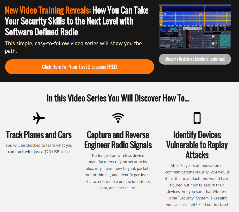
We’ve recently found what looks to be a new online video based course that uses the RTL-SDR to teach basic software defined radio topics. The course is not free, it is priced at $29.99, but the first three videos are free. Judging from the first three videos the content appears to be quite basic, but is presented in a very clear way that may be useful for beginners. Currently the lessons include:
Course Overview
Welcome to the exciting world of Software Defined Radio. In this video, we’ll discuss what SDR is, and why it’s such a hot button topic right now.
Setting up the environment
In this module, we’ll setup our environment for development. If you’re already very comfortable with Ubuntu, you might want to just follow the guide below.
Browsing the spectrum
In this module, we’ll cut our teeth on GRQX, and learn a little about the radio spectrum.
Signals Intelligence
In this module, we’ll learn how to find transmissions in the frequency domain, and capture them to disk for offline analysis.
Modulations
In this module, we’ll learn how to identify two types of basic digital transmissions, and talk a little about the history of radio.
Demodulation – Part 1
In this module, we’ll practice capturing signals in the wild, identifying the modulation, and demodulating the signal with GNU Radio.
Demodulation – Part 2
In this module, we’ll learn about clock recovery. And we’ll pull out packets from the garage door remote.
It also appears that they plan to have some live classes in the future.
We note that there are also alternative SDR training courses available such as Micheal Ossmanns lessons at greatscottgadgets.com/sdr.
To make it actually work as an SDR he also wrote some code to utilize the development board’s ARM processor which processes the ADC input into a radio signal, demodulates it and then turns it into audio via the boards DAC and speaker. The radio can tune from 8 kHz up to about 900 kHz.
The only real extra hardware in Alberto’s system is a low pass filter for anti-aliasing and impedance transformation, and a reconstruction filter to get sound to the speakers from the DAC. He also used the boards LCD screen to implement a full GUI tuning system.
The Free and Open Source Developers Meeting (FOSDEM) is looking for SDR presentations to give at this years conference in Brussels, Belgium which will be held on January the 80th & 31st of January.
Software Radio has become an important tool to allow anyone access the EM spectrum. Using free software radio libraries and applications and cheap hardware, anyone can now start hacking on wireless communications, remote sensing, radar or other applications. At FOSDEM, we hope to network all these projects and improve collaboration, bring new ideas forward and get more people involved.
The track’s web site resides at: http://gnuradio.org/redmine/projects/gnuradio/wiki/FOSDEM
Here, we will publish updates and announcements. The final schedule will be available through Pentabarf and the official FOSDEM website.
To suggest a talk, go to https://penta.fosdem.org/submission/FOSDEM16 and follow the instructions (you need an account, but can use your account from last year if you have one). You need to create an ‘Event’; make sure it’s in the Software Defined Radio track! Lengths aren’t fixed, but give a realistic estimate and please don’t exceed 30 minutes unless you have something special planned (in that case, contact one of us). Also, don’t forget to include time for Q&A. Typical slot lengths would be 30 Minutes including QA.
You aren’t limited to slide presentations, of course. Be creative. However, FOSDEM is an open source conference, therefore we ask you to stay clear of marketing presentations. Of course, we like nitty-gritty technical stuff.
We will reserve time for interactiveness, it won’t all be talks.
If you are qualified and interested in giving a talk the submission deadline is December 4th 2015.
Last week a reader of RTL-SDR.com wrote into us to let us know about some experiments that he had been performing with the telescopic stock antennas provided in our RTL-SDR dongle packages. The reader had built a corner antenna reflector in order to improve reception in one direction. We are posting his write up and results below:
This tutorial will discuss the use of a Corner Reflector with a monopole antenna, i.e. the stock RTL-SDR antenna. To keep this tutorial concise, the reader is encouraged to study the Wikipedia pages for details about Corner Reflector Antennas, Dipoles and Monopoles.
Corner Reflector Antennas are very easily constructed from 2 A4-sized cardboard panels, covered with tinfoil. This allows for a foldable and transportable external reflector to the built-in wifi antennas of a laptop, which are located on the upper corners of the display.
The reader is pointed to the fact that corner antennas are based on a Dipole, where the stock RTL-SDR antenna is a Monopole, so some adjustments will have to be made, which is discussed and explained later in this text. If there are real antenna specialists reading this, they are encouraged to do a more thorough writeup on the exact mechanism of a monopole-based corner reflector antenna, as there was little information to be found on the internet.
The experiment started as an attempt to receive a DVB-T signal centered around 506 MHz, from a mast about 10 miles away. Indoors. This should have given a clear and strong signal, but alas, the signal was very weak.
Initial reception of the DVB-T signal with the stock antenna and no modifications.
Reading up on Monopoles and their need for a ground plane, the magnetic base of the 14 cm long antenna was placed on a metal cooking pot. The signal was a lot stronger. (The middle part of the waterfall plot above.) Clearly a wooden table is not much of a ground plane.
Next a Corner Reflector was made from tinfoil and a cardboard box, much to the dismay of the resident Feline Overlord that had seized it. 🙂 A triangular piece was added for rigidity and as a ground plane. The Monopole antenna was placed on the ground plane triangle in the middle of the 90° corner and at the correct distance from the fold in the reflector. i.e. the Focal Axis, but the gain was less than the theoretical 10dB so this setup was unsuccessful. (Upper part of waterfall plot above.)
The breakthrough came when I wanted to study the effect of a larger ground plane. For this I put the corner reflector sideways and put the monopole on the outer edge to reduce possible reflections from the standing panel. There was only a slight effect compared to the cooking pot, so I decided to progressively move the monopole towards the back panel in order to see if the additional reflection would get some more gain. When I reached about 10 cm distance from the panel, the waterfall plot exploded with a very powerful signal! See the picture below for the transition from wooden table to the sideways configuration. (On top of the waterfall plot there is some residual from the ground plane cooking pot test.)
DVB-T signal with corner reflector.
The setup looks like this:
For a few days I was baffled as to why the corner reflector behaved this way. It had already dawned on me that the diagonal distance from the fold till the antenna tip was 14 cm in this configuration, so 1/4 WL. It was only after I visualized how a monopole works, that I understood: a 1/4 WL monopole is physically a quarter wavelength open ended resonator. i.e. at the base/feed point the electric current is maximum and the voltage minimum. At the tip it is reversed, with maximum voltage and zero current. See this page for details: http://www.radio-electronics.com/info/antennas/vertical-antennas/quarter-wavelength.php
Alternatively, the polar plot of a Corner Reflector Antenna also shows that the signal is weakest/zero in the direction of the panels, where the monopole base is located, while the maximum signal is along the center line between the 2 panels, which is where the tip of the monopole is located. Hence the signal *difference* over the monopole is thus maximized and this way it works best. As stated in the beginning, if an antenna expert can write up a better explanation, please contact the maintainer of the RTL-SDR Blog.
In retrospect, the original setup I tested could not work optimal since the entire monopole is irradiated equally if it is aimed along the Focal Axis. Moreover it was suspected that the mirror image antenna that makes a monopole work, was distorted because of the electrical contact between the triangular ground plane and the reflector panels. A test with an isolated triangular ground plane was planned but has now been permanently shelved.
For those who want to re-create the experiment, these are the reflector dimensions:
2 panels of 42*25cm, joined along the longest side.
36*25*25cm triangle at the bottom. This should give a 90° angle between the 2 largest panels.
The tinfoil can be wiped smooth and attached with some glue.
So to summarize;
Make sure you have a good ground plane!
A Corner Reflector Antenna can be constructed at frugal cost with a cardboard box and tinfoil. Larger reflectors are better, especially in the plane perpendicular to the Monopole, so it is better to have wide reflectors in stead of high reflectors.
Make sure the base of the stock monopole antenna is located in an area with low signal strength and the tip is located in an area of maximum signal, therefore maximizing the *difference* between base and tip of the Monopole. Usually this means perpendicular to the Focal Axis of the reflector panels.
Distances and Monopole lengths can easily be adjusted for various frequency ranges, making this a very versatile modification or enhancement to the stock antenna.
Speculation: Since there is a focal Axis rather than a Point (i.e. like a Parabolic Dish), the sideways configuration might be more suitable for tracking a moving satellite across the horizon, ideally at 45° azimuth.