An RTL-SDR Phase Correlative Direction Finder

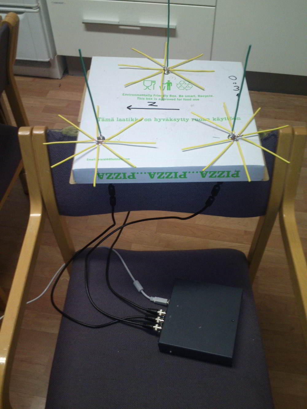
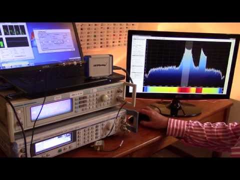
Over on YouTube user Tatu Peltola has uploaded a video showing his RTL-SDR based phase correlative direction finder in action. This set up uses three RTL-SDR dongles and three antennas to measure phase differences and thus determine the direction towards a signal source. All three RTL-SDR’s must be coherent, meaning that all three of their 28.8 MHz clock signals must come from the same source. 

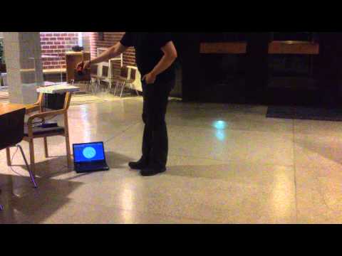
In the video Tatu walks around the three antennas with a handheld radio. An arrow on a laptop screen points in the direction of the transmitter.

A known problem with RTL-SDR’s is that even with the clock sources synchronized there is still an unknown cause of additional phase shift. To solve this problem Tatu writes:

Each rtl-sdr is fed from the same reference clock to make their phase shift remain constant. They still have unknown phase shifts and sampling time differences relative to each other. This is calibrated by disconnecting them from antennas and connecting every receiver to the same noise source. Cross correlation of the noise gives their time and phase differences so that it can be corrected.

The three antennas used for direction finding.
RTL-SDR phase correlative direction finder

RTL-SDR Heat Dissipation as seen by a Thermal Camera

The RTL-SDR is known to get quite hot during operation and when it gets too hot reception of frequencies over 1.2 GHz can be degraded. Marko Cebokli wrote into us at RTL-SDR.com to show us some thermal imaging pictures that he has made of the RTL-SDR PCB. The images clearly show that the hottest part of the PCB is the R820T chip. The RTL2832U chip stays cool and the only other hot component on the PCB is the voltage regulator. In the post Marko also explains his conclusions on why the reception fails at frequencies over 1.2 GHz when it gets too hot.

The images show that the top of the R820T chip reaches a temperature of 85 degrees Celsius after just 10 minutes of operation. The underside of the chip reaches 68.9 degrees Celsius. Marko writes that these temperatures may be even higher when the RTL-SDR is placed inside the plastic case.

In general the RTL-SDR runs fine at these temperatures, but cooling the R820T chip will improve performance when tuning into signals that are higher than 1.2 GHz, for example with L-band satellites. Other RTL-SDR enthusiasts have cooled their RTL-SDR’s with thermal pads, heatsinks, fans and oil.

The RTL-SDR PCB seen with a thermal camera

Controlling Siri and Google Now with a Yagi and USRP

Wired magazine have recently run a story that shows how French researchers have discovered a method for remotely controlling modern smartphones through an RF attack that targets the voice control functionality called Siri on the iPhone and Google Now on Android. The attack only works for phones that have voice commands enabled, and there must be a pair of microphone enabled headphones plugged in.

The attack is pretty simple in theory. It works by using a software defined radio to transmit a high power amplitude modulated CW signal that will be picked up by the microphone’s cable which acts like an antenna. The AM CW signal is modulated in such a way that the built in low pass filter in the microphone works as a demodulator and turns the signal into an audio voice command.

In their experiments they were able to use a USRP SDR, amplifier and directional Yagi antenna to cause a smartphone to load up their webpage. The same attack could probably be performed with a cheaper HackRF SDR. 

A talk by the researchers was uploaded to Google earlier this month and is shown below.

HIP15-TALK:You don't hear me but your phone's voice interface does

Another L-Band Antenna Build and comparing L-Band reception on the RTL-SDR, HackRF and SDRplay

Over on Reddit user killmore231 has made a post showing his comparison of L-Band reception with RTL-SDR, HackRF and SDRplay software defined radios. killmore231 built the L-band patch antenna which Adam 9A4QV showed how to build on his YouTube channel late last month.

When testing the antenna on his RTL-SDR he saw no reception of any L-band signals at all. The RTL-SDR requires an external LNA to properly receive signals at this frequency range, which he did not have. Next he tried it on his HackRF and saw that some signals were weakly visible. When he tried it on his SDRplay the L-band satellite signals were clearly visible, probably due to the SDRplay’s good sensitivity at this frequency range and the fact that it has a built in LNA. His results show that the SDRplay is a good SDR for receiving L-band satellites as it does not need an external LNA for decent reception. An external LNA may still be needed if a long run of coax cable is used however.

SDRplay reception of L-band satellite signals with no external LNA.
L-band patch antenna

Passively Cooling the RTL-SDR with a Thermal Gap Pad

John Mills recently wrote in to us at RTL-SDR.com to show us how he cools his RTL-SDR by using a thermal gap pad stuck to the entire bottom of the RTL-SDR PCB. A thermal gap pad is a soft pliable material that is often used to interface between electronic chips and heatsinks. The gap pad forms into tight hard to reach spaces and conducts heat towards the heatsink. It is not electrically conductive, so the entire bottom of the RTL-SDR can be stuck to the thermal gap pad, which is then stuck to a metal heat sink.

John uses a thermal gap pad made by Bergquist, with part number GP5000S35-0.100-02. This gap pad is 0.1 inches thick, is easily cut with a craft knife and is tacky so it easily sticks to the heatsink and RTL-SDR PCB. It has a thermal conductivity of 5W/m.k. John uses the pad to help to cool the R820T, RTL2832U and voltage regulator chips. It has been shown in some previous posts that by cooling the R820T chip increased sensitivity can be obtained, especially at frequencies above 1.2 GHz.

He writes that if there is sufficient interest then he may consider selling strips of it on eBay. You can contact him at sdr_AT_milairuk.co.uk.

Below we’ve posted images of Johns thermal pad cooled RTL-SDR’s, along with his comments on them in the captions.

Inside latest SDR / Latest SDR - "This is my latest version using a R820T2 version, and I have also fitted this with a TCXO. In this version I also used a 1Mohm and 47nF to ground the USB shield wire as in a previous post. This version only uses one metal spacer and the end  of the PCB is secured by two M2 nylon screws / nuts. Case from China RF on Ebay."
Open SDR – “Just held onto a heatsink with two pieces of string ! Then this sits on another larger heatsink using another piece of Gap Pad to hold it – this has been working in my garden shed now for over 2 years feeding ADSB data”
Diecast Box SDR – "in this one I have made two small threaded metal clamps, lined with gap pad and tightened just enough to keep the PCB in good contact with the gap pad underneath and the diecast box. I use small BNC to MCX pigtails off Ebay to connect to the antenna socket. I also remove the LED and place through the box as can be seen."
Diecast Box SDR – “in this one I have made two small threaded metal clamps, lined with gap pad and tightened just enough to keep the PCB in good contact with the gap pad underneath and the diecast box. I use small BNC to MCX pigtails off Ebay to connect to the antenna socket. I also remove the LED and place through the box as can be seen.”
Inside latest SDR / Latest SDR - "This is my latest version using a R820T2 version, and I have also fitted this with a TCXO. In this version I also used a 1Mohm and 47nF to ground the USB shield wire as in a previous post. This version only uses one metal spacer and the end  of the PCB is secured by two M2 nylon screws / nuts. Case from China RF on Ebay."
Inside latest SDR / Latest SDR – “This is my latest version using a R820T2 version, and I have also fitted this with a TCXO. In this version I also used a 1Mohm and 47nF to ground the USB shield wire as in a previous post. This version only uses one metal spacer and the end of the PCB is secured by two M2 nylon screws / nuts. Case from China RF on Ebay.”
Latest SDR - Outside
Latest SDR – Outside

Comparing RTL-SDR’s on L-Band Reception, Tuner Temperatures and Passive Cooling

Over on Reddit user MaxWorm has been doing some experiments with comparing various RTL-SDR dongles on L-band (1 – 2 GHz) reception. Previously we wrote a tutorial on decoding Inmarsat signals which are at around 1.5 GHz and noted that the R802T/2 dongles can have some trouble at these frequencies.

It is known that the R820T/2 is not as good as the older now rare and expensive E4000 tuners at frequencies above 1.5 GHz, and it is also known that sensitivity decreases as the temperature of the R820T/2 increases, especially at frequencies above 1.5 GHz.

MaxWorm tested an R820T, R820T2 and two E4000 sticks at receiving L-band frequencies. He found that one of the E4000’s performed the best, but surprisingly the other E4000 dongle was totally deaf in the L-band. The R820T and R820T2 dongles performed similarly – not as good as the best E4000, but not as bad as the worst. All tuners exhibited reduced signal strength when warm.

In another post MaxWorm also measured the temperature of the tuner chips in each of his units, and created a simple heatsink for one of his R820T2 dongles. His results show that the heatsink passive cooling works well, significantly cooling the R820T2 chip. His measurements are copied below:

R820T2 in Plastic case:
R820T2: 77°C top / 74°C bottom
RTL2832: 56°C top / 54°C bottom

R820T2 bare PCB:
R820T2: 62°C top / 63°C bottom
RTL2832: 43°C top / 42°C bottom

R820T2 in Alu-Case with Alu “L-Bridge” on Tuner:
R820T2: top 37°C / bottom 47°C
RTL2832: top 49°C / bottom 40°C

E4000 in plastic case:
E4000: 37°C top / 37°C bottom
RTL2832: 46°C top / 40°C bottom

bare E4000 PCB:
E4000: 37°C top / 32°C bottom
RTL2832: 40°C top / 37°C bottom

Other experimenters have previously applied fan cooling and oil cooling to RTL-SDR dongles to cool them and increase sensitivity.

RTL-SDR with heat sink to aluminium case.
RTL-SDR with heat sink on the R820T2 chip connectoed to the aluminium case.
L-Band Reception Results for an R820T, R820T2 and two E4000 dongles.

Demonstrating the Dynamic Range on the SDRplay RSP

The SDRplay radio spectrum processor (RSP) is a $150 USD software defined radio that can be considered as a next stage level up from the RTL-SDR dongle. We also consider it a competitor to the $199 USD Airspy SDR.

Over on YouTube the SDRplay designers have posted a video that demonstrates the dynamic range that is possible with their SDR. Dynamic range is a measure that defines the range between the strongest and weakest signal that can be received. So for example, if you have two signals near to each other on the frequency spectrum, dynamic range defines how much stronger can one signal be compared to the other before the weaker signal disappears into the noise.

In the experiment they use two frequency generators to generate a simulated wanted signal at 98.4 MHz and an unwanted blocking interferer at 98.7 MHz. They show that by reducing the IF bandwidth in their configuration screen and thus tightening the internal filters that the dynamic range can be increased to about 70 dB.

Previously Leif sm5bsz performed some similar tests, comparing many SDRs against one another, but did not utilize the programmable IF filters in the SDR Play RSP perhaps undervaluing the best possible dynamic range by about 5-10 dB.

SDRplay RSP FM Dynamic Range Demo

Mitigating QRM (Interference) with an Antenna Phaser

Over on YouTube user London Shortwave has posted a video showing his antenna phasing system in action with a Funcube Dongle Pro+ and SDR# running on a tablet. An antenna phaser reduces unwanted noise by using two antennas and positioning one “noise” antenna so that it receives the unwanted noise strongly, and positioning the main antenna to receive the desired signal as best as possible. Then the signals are combined by a phaser unit in such as way that the unwanted noise is subtracted from the desired signal.

In his experiments London Shortwave discovered that an ethernet over Power adapter used by one of his neighbours was causing the shortwave spectrum to get completely obliterated by noise. His video shows the effect of turning his phaser unit on and off when trying to reduce this noise. London Shortwave has also done a very nice writeup on dealing with urban interference on shortwave, and includes a section that discusses antenna phasing.

The antenna phaser set up
QRM mitigation with antenna phasing