Tutorial on Properly Positioning a Preamp (LNA) in a Radio System

Radio blogger Anthony Stirk has made a post on his blog explaining some critical concepts behind understanding why it is important to position a low noise amplifier (LNA) near the radio antenna, rather than near the radio. In the post Anthony explains how the Noise Figure (NF) and linearity (IP3) of a radio system affect reception.

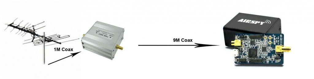
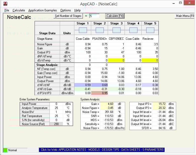
Using the free AppCAD RF design assistant software, Anthony explains how the noise figure of a system increases with longer coax cable runs, and how it can be reduced by placing an LNA right next to the antenna. He also explains why the sensitivity of the radio won’t increase if the LNA is placed close to the radio instead.

In addition to this, he also explains why adding more LNA’s to a system decreases the linearity (IP3) of the system and that if the receiver has a built in LNA that the system linearity can be severely degraded by adding extra LNA’s, causing easy overloading and intermodulation. In conclusion Anthony writes the following:

In summary, a setup with a good antenna system connected to a receiver with a built in LNA:

  • May not benefit from having a preamp at the antenna.
  • The presence of a built in LNA is detrimental to the linearity and may degrade the signals.

So in conclusion:

  • Put the preamp as close to the antenna as possible.
  • Receivers with a built in LNA may not get the most out of an antenna system or preamp.
  • Proper gain distribution guarantees better performance than one-size-fits-all solutions, both in terms of sensitivity and strong signals handling.

Optimal Setup: Antenna -> LNA -> Coax -> Receiver
NF and Linearity Calculations
NF and Linearity Calculations in AppCAD

SDR# updated to revision 1400 & SDR Touch updated to V2.6

The popular SDR# software which is often used together with RTL-SDR dongles has recently been updated to revision 1400. This new revision brings an interesting new feature which automatically estimates and displays the peak, floor and signal to noise ratio (SNR) values of the currently tuned bandwidth. Watching the SNR metric is very useful when tuning the RF gain settings, as best reception is obtained when the SNR value is maximised. The author also writes that there have been several radical changes to the code that leverage the latest .Net 4.6 framework which should improve the signal processing quality, CPU usage, user experience and hardware support. The changelog is pasted below:

Enhanced the Center tuning mode and extended it for RTL-SDR;
Enhanced the spectrum display;
Changed the frequency labelling to use multiples of 2.5/5/10 or frequency steps;
Added Peak, Floor and SNR estimation for the selection;
Enhanced the defaults for better user experience;

We note that some plugins may break with this update so be sure to make a backup if upgrading. Vasili, one of the most active SDR# plugin programmers has updated most of his plugins to work on this new version now.

Revision 1400 of SDR# with SNR estimation.

In addition to this update, over on the Android OS the popular mobile app SDRTouch has been updated to version 2.6. This new version brings the following features and improvements:

  • Baseband recording and file playback
  • Direct sampling support for full-band receivers
  • Improved SSB image rejection
  • Fixed tuning step
  • Manual filter bandwidth
  • Improved accessibility
  • Bug fixes

Reverse engineering a wireless thermostat with an RTL-SDR

When Tom Taylors home heating boiler was replaced the builders also replaced the old wired rotary thermostat with a digital wireless one. It sounds good, but Tom soon discovered that the thermostat UI was terrible and that the buttons were horrible to press, making him prefer to shiver in the cold. So Tom decided to see if there was a smarter way to control the heating.

When Tom investigated the thermostat, he discovered that the wireless unit transmitted in the unlicensed 433 MHz band and that the thermostat only transmitted two commands, turn on or turn off. By using his RTL-SDR and the CubicSDR software on his Mac he was able to detect the short blip of the thermostat wireless signal. Next he recorded the on and off signals and opened the sound files in Audacity, an audio processing software tool. In Audacity he was able to compare the sound waveforms of the on and off signals.

From his analysis he discovered that each signal consisted of a preamble and then an on or off command which is repeated twice, presumably to reduce the likelihood of interference. Tom also discovered that the commands were encoded with pulse width modulation.

From this knowledge Tom was then able to use a cheap 433 MHz transmitter together with an Arduino microcontroller board and a short script to create identical on or off transmissions that control the boiler. Tom writes that his next steps are now to create a heating schedule based on his families shared calender, make a thermostat control loop and create a web connected interface with a Raspberry Pi.

The 433 MHz thermostat on/off signal detected with an RTL-SDR in the CubicSDR software

Building an L-band helical antenna for Inmarsat

Previously in August of this year we wrote an article showing how to decode Inmarsat satellite STD-C NCS EGC messages with an RTL-SDR. Inspired by this article, RTL-SDR.com reader Mario Filippi, N2HUN has written in to show us how he built an L-band helical antenna to receive these signals. A helical antenna is one of the better choices for receiving Inmarsat signals as it will provide higher gain when compared to a patch antenna, however the disadvantage is that it is much larger. Of related interest, Adam 9A4QV also recently showed us a video detailing the correct dimensions for building an air gap patch antenna.

Mario’s Inmarsat antenna consists of a 90cm Ku band dish, a homebrew L-band LHCP helical antenna and an inline amplifier. He used the assembly instructions found on UHF Satcom’s page at http://www.uhf-satcom.com/lband and scavenged most of the parts from his junk box. To help others with the construction of a similar antenna Mario has also created a document detailing the construction of the antenna with several useful build images (.docx file).

Helical Inmarsat antenna feed for a 90cm Ku band dish

Mario has also recently given a presentation about the RTL-SDR to the Mid Atlantic States VHF Conference entitled “SDR Dongle for VHF/UHF Reception”. The presentation is an overview of the RTL-SDR dongle and many of its interesting applications, including several screenshots of software in action (dropbox) (mega mirror).

Reverse engineering a public parking electronic display to play Tetris

Recently we received an email from RTL-SDR.com reader @Ivoidwarranties about his latest project which involved using a HackRF to reverse engineer the RF protocol used by a public parking electronic display. Once reverse engineered @Ivoidwarranties used a XR-2206 monolithic function generator, hybrid RF amplifier and an Arduino to create a device that overrides the public parking display and plays a game of Tetris on it.

We don’t have any details on the HackRF reverse engineering side of things, but he has uploaded a video to YouTube showing the hack in action.

Real hacking of public parking electronic display

Airspy Revision 2 Released

The Airspy is a $200 USD software defined radio that has a frequency range between 24 – 1700 MHz, bandwidth of up to 10 MHz and a 12-bit ADC. We consider it to be a good upgrade from those who have gotten into SDR via the low cost RTL-SDR.

Recently the Airspy hardware was updated to revision two. The new revision improves upon the first design by reducing noise, improving the USB connector, improving the ESD protection and improving compatibility with the soon to be released Spyverter upconverter. The full release is pasted below:

We have sensitive ears! The demand for ever cheaper, higher performance and ruggedized SDR receivers is driving the professional market. Due to the large demand from our professional customers, we upgraded recently our original Airspy One design to Revision 2. This new revision improves the following points:

  • Better USB noise immunity
  • Better ESD protection on the RF input
  • Added ESD protection on the dual High Speed ADC inputs
  • Better RF Shielding
  • Better RF Filtering
  • Replaced the USB connector with a custom designed, more robust, 4 through hole points model
  • Better thermal stability
  • Better compatibility with the SpyVerter

The old revision is no longer produced, and all new shipments will be based on the R2. We are eager to get your feedback about these improvements!

The Airspy software defined radio


Measuring the return loss of the standard RTL-SDR whip antenna

Most low cost sellers of RTL-SDR dongles bundle them with a cheap fixed length whip antenna. Over on YouTube Adam 9A4QV has measured the return loss of these whip antennas with his vector network analyzer to determine at what frequencies you can expect decent performance. The return loss indicates at what frequencies you can expect a good impedance match, and thus a good standing wave ratio (SWR). The lower the return loss the better the impedance match and thus less power is wasted in the antenna meaning better receive performance.

Adams results found that without a ground plane the antenna has a return loss of less than -10dB at around 625 MHz and about 1.40 GHz. With a ground plane (placed on a metal surface) the antenna has good performance at around 535 MHz, 1.4 GHz and 2.4 GHz. This is not surprising as the antenna is designed for DVB-T TV, of which most signals are transmit near 535 MHz. Adam also remarks that the performance at the ADS-B frequency of 1090 MHz with or without ground plane is quite bad.

DVB-T antenna return loss with ground plane
DVB-T dongle whip antenna test

Demonstrating the RTL-SDR based “Etch-A-SDR” Portable SDR

Over on YouTube user devnulling has uploaded a video showing his “Etch-A-SDR” project. This project involved creating an all-in-one SDR device out of an Odroid C1, Teensy 3.1 and an RTL-SDR dongle. The Odroid C1 is an embedded computer, similar to the Raspberry Pi 2 and the Teensy 3.1 is a microcontroller development board. The “Etch-A-SDR” is named as such because of its resemblance to an Etch-A-Sketch toy. It has two knobs that can be used for tuning and several side buttons for changing demodulation modes etc.

Upon boot the Etch-A-SDR opens GQRX and is ready for tuning within seconds of turning it on. In addition to using it as a portable SDR with GQRX the Etch-A-SDR can also be booted into normal Linux mode and into Etch-A-Sketch mode, where it operates as a normal Etch-A-Sketch toy.

The code can be downloaded from https://github.com/devnulling/etch-a-sdr.

The Etch-A-SDR portable SDR