Wirelessly transmitting sound from a parabolic microphone with an FM Transmitter and receiving it with an RTL-SDR

Parabolic microphones allow listeners to clearly hear sounds from far away. They are often used by bird call enthusiasts and also probably by spies. A parabolic microphone works by using a dish to concentrate distant sound onto an amplified microphone and they have been commercially available since the 60’s as demonstrated by this old Radioshack ad.

An old parabolic micrphone advertised in a radioshack catalogue from the '60's
An old parabolic micrphone advertised in a radioshack catalogue from the ’60’s

Usually, the listener uses a pair of headphones directly tethered to the parabolic microphone and walks around with the dish in hand. However, this week electronics hobbyist Mario Fillipi wrote in to RTL-SDR.com to let us know about his project in which he created a wirelessly operated parabolic microphone.

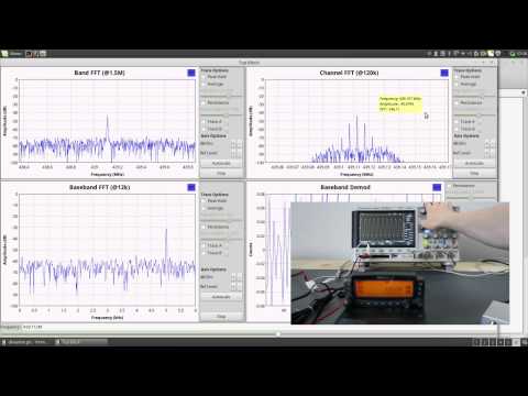
To do this Mario connected a wireless FM transmitter to the headphone output of his home made parabolic mic, mounted the dish on a tripod, and then used his RTL-SDR to receive the FM transmission and demodulate the remote sounds. Of course reception can be done with any suitable radio, but the RTL-SDR provides the advantage of being able to easily manage, record and analyze the received audio.

The parabolic micrphone with FM transmitter
The parabolic microphone with FM transmitter

Mario used his wireless parabolic microphone to record the sounds of finches in a bird house that was about 70 feet (21 meters) away. Then he writes that in HDSDR he was able to analyze the finches calls in the audio spectrum waterfall. He noticed that the calls were in the 2300 – 6000 Hz audio range and that each call’s “imprint” or audio signature was very similar and could be easily recognized. You can listen to the finches calls that were recorded by the RTL-SDR in the audio file below.

Looking at the Finch calls' "imprints" in the audio spectrum waterfall in HDSDR
Looking at the Finch calls’ “imprints” in the audio spectrum waterfall in HDSDR

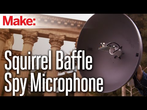
Mario writes that this can be done with any commercially available parabolic microphone, but if you want to know how to build your own wireless parabolic microphone then check out Make magazine’s article on Mario’s work. The article shows in detail how to build a parabolic microphone out of a squirrel baffle (a bowl shaped piece of plastic that prevents squirrels from eating bird feed), a Velleman Super Stereo Ear kit (microphone + amplifier kitset) and a standard wireless FM transmitter. Mario writes that the audio range of his home made parabolic mic is about 100 feet (30 meters). A video from Make magazine showing Mario’s home made parabolic mic is shown below.

Weekend Projects - Squirrel-Baffle Spy Microphone

Understanding FM deviation, Modulation Index and Sideband theory with an RTL-SDR Dongle

Over on YouTube user MrCircuitMatt has uploaded a video where he explains the concepts of FM deviation, modulation index and sidebands using an RTL-SDR dongle as the receiver, and a function generator connected to a Kenwood TM-D700 transceiver as the transmitter.

In the video he transmits a modulated signal and uses a GNU Radio flowgraph to demonstrate and visualize what happens when the modulation frequency is changed. Later in the video he moves to pen and paper to explain the theory behind the results he saw.

HB9UF: FM deviation, modulation index and sidebands with an RTL SDR dongle

Decoding Public Utility Meters with an RTL-SDR

Over on YouTube a talk about decoding water and electricity usage meters with an RTL-SDR has been uploaded from the 2015 Camp++ conference in Hungary. The presenter, Stef writes:

Budapest public utilities started to roll out some new metering devices for water and heating (at least in my block). The plumbers who should install these could not tell me about the privacy protections considered, as I was a bit worried about the things leaking information over radio-waves, so I built a radio and reversed the messages.

The talk shows how the presenter was able to reverse engineer the FSK wireless protocol of his heating meter with help from some patent information that he found on the web. Using a GNU Radio flow graph that he created he was able to extract information such as total energy consumption and temperature readings.

Being a security themed conference, the presenter also discusses some of the security risks associated with wireless meters such as whether or not the meter can be used to detect if someone is currently at home.

The code he wrote and used can be found at https://github.com/stef/smeter and https://github.com/jmichelp/gr-wmbus.

Camp++ 0x7df // stef: Dumbmeters in Public Utilities

An example water meter that could be monitored with an RTL-SDR dongle

BA5SBA Direct Sampling Kit English Build Instructions

The BA5SBA direct sampling kit is a kitset PCB that combines with a standard (included) RTL-SDR dongle in order to enable the direct sampling mod. The direct sampling mod is a hardware modification that can be applied to any RTL-SDR dongle in order to enable HF reception capabilities. The BA5SBA kit improves upon some of the problems with the direct sampling mod by adding additional features such as a low pass filter to block broadcast FM interference, a matching transformer to better match the RTL2832U’s input impedance, extra power supply filtering, SMA connectors for HF and VHF/UHF (UV), an aluminium case and a bias tee.

The BA5SBA direct sampling RTL-SDR can be bought as a kit that requires hand assembly for about $30 USD or as a fully assembled product for about $50 USD. It is usually listed on Amazon and eBay as a “100KHz-1.7GHz full band UV HF RTL-SDR USB Tuner Receiver/ R820T+8232 Ham Radio”

Recently, RTL-SDR.com reader Simon (MW0SGD) bought one of these kits and discovered that the English instructions were very rare and hard to come by. We’ve decided to post these English instructions here for any future buyers who may search for them as this post should show up on Google. Simon also notes that “most of the instructions on the internet wind the inductors on a 5mm former. This says to use a 3mm one, which I did and it works ok.”

The English pdf instructions can be downloaded here.

The BA5SBA Direct Sampling RTL-SDR Kit

New Raspberry PI Remote RTL-SDR GUI Software: MNM4SDR

Recently RTL-SDR.com reader Slaven Krilic wrote in to use to announce his project called MNM4SDR which stands for Monitoring Network Manager for RTL-SDR. The software allows you to set up a remote Raspberry PI embedded computer with an RTL-SDR dongle attached and access it remotely through a Windows PC GUI.

Unlike other server software such as rtl_tcp, raw IQ data is not sent over the network. Instead audio is first compressed in lossless FLAC or OGG formats. This allows you to use much slower network or internet connections. The software also allows you to collected RF scans over a large bandwidth in a similar way to rtl_power.

The software works over an SSH connection and requires that you have RTL-SDR and VLC set up on your Rasperry Pi first.

MNM4SDR: Monitoring Network Manager for RTL-SDR

RTL-gopow: New heat map tool

Rtl_power is a tool that allows you to create wide band signal strength heat maps over a long length of time. It works by very quickly hopping across the spectrum, capturing the RTL-SDR bandwidth of about 2 MHz at a time, and then displaying it on a heat map. This is useful for seeing what frequencies are active and at what times. 

Usually to obtain a heat map with rtl_power you need to record the data first, and then pass it through a Python program called heatmap.py which creates the heat map image file. Now there is rtl_gopow which is a new program that directly creates a PNG heat map file from an rtl_power sweep. It is currently available for OSX, Linux, Linux ARM, and Windows.

You can download the binary releases here.

2.5 hour long heat map generated by RTL_GOPOW

Uni-SDR Link: Control SDR Console V2 with Unitrunker

A new program called Uni-SDR Link has just been released. This software allows Unitrunker to control SDR-Console V2.

Unitrunker is software that allows you to follow trunked voice conversations, and SDR-Console V2 is a general purpose receiver, similar to other software such as SDR#. The authors write:

This applications sole purpose is to allow Universal Trunker (aka Unitrunker) to control the tuning frequency of individual VFO’s in SDR Console v2. This is achieved by translating Unitrunker Receiver Control commands into a format accepted by SDR Console. Communication occurs over virtual com / serial ports.

Uni-SDR Link has been tested on Windows 7 & Windows 8 and requires .NET Framework version 4.0 or greater.

Just download & launch. No installation required.

The Uni-SDR-Link.chm file contains help for the application should be placed in the same directory as the Uni-SDR-Link.exe.


International Space Station set to Transmit SSTV this Weekend (July 18 – 19)

To commemorate the 40th Anniversary of the Apollo-Soyuz mission the International Space Station (ISS) is set to transmit 12 Slow Scan TV (SSTV) images this weekend. The images are set to transmit Saturday morning, July 18 10:30 UTC and will run through until Sunday, July 19 21:20 UTC, but they note that the dates are tentative and could be subject to change. The images will be transmitted at 145.80 MHz and will probably be sent in the PD180 SSTV mode with 3 minute breaks between each transmission.

SSTV is a type of radio protocol that is used to transmit low resolution images over radio. An RTL-SDR with appropriate antenna can be used to receive these images from the ISS. The signal is usually quite strong, so even a simple whip or long wire antenna may receive these images if placed in a good unobstructed view of the sky. 

As with the last ISS SSTV event we suggest that to decode the images you use SDR# and pipe the audio into MMSSTV, a freeware SSTV decoding software program. We also suggest using the settings recommended by “happysat”, which are enabling “Auto slant” and “Auto resync” under Options->Setup MMSTV->RX.

To know when the ISS is overhead you can track it online using heavens-above.com or isstracker.com. If using heavens-above to predict pass times remember to set it to show all passes, not just the visible ones. Received SSTV images can be submitted to the ARISS Gallery.

This event is being discussed on Reddit here. Here is the official release from ariss.org:

40 years ago this week, the historic joint Apollo-Soyuz mission was conducted.   Apollo-Soyuz (or Soyuz-Apollo in Russia) represented the first joint USA-Soviet mission and set the stage for follow-on Russia-USA space collaboration on the Space Shuttle, Mir Space Station and the International Space Station.  The Soyuz and Apollo vehicles were docked from July 17-19, 1975, during which time joint experiments and activities were accomplished with the 3 USA astronauts and 2 Soviet cosmonauts on-board.  Apollo-Soyuz was the final mission of the Apollo program and the last USA human spaceflight mission until the first space shuttle mission in 1981.

To commemorate the 40th anniversary of this historic international event, the ARISS team has developed a series of 12 Slow Scan Television (SSTV) images that will be sent down for reception by schools, educational organizations and ham radio operators, worldwide.The SSTV images are planned to start sometime Saturday morning, July 18 and run through Sunday, July 19.  These dates are tentative and are subject to change. The SSTV images can be received on 145.80 MHz and displayed using several different SSTV computer programs that are available on the Internet. 

We encourage you to submit your best received SSTV images to:
http://spaceflightsoftware.com/ARISS_SSTV/submit.php

The ARISS SSTV image gallery will post the best SSTV images received from this event at:
http://spaceflightsoftware.com/ARISS_SSTV/index.php

Also, as a special treat, on Saturday July 18 the ISS cosmonauts will take time out to conduct an ARISS contact with students attending the Moon Day/Frontiers of Flight Museum event in Dallas Texas.  This Russian cosmonaut-USA student contact is planned to start around 16:55 UTC through the W6SRJ ground station located in Santa Rosa, California.  ARISS will use the 145.80 MHz voice frequency downlink (same as the SSTV downlink) for the Moon Day contact. More details about these contacts are provided at Upcoming Contacts.

The ARISS international team would like to thank our ARISS-Russia colleague, Sergey Samburov, RV3DR, for his leadership on this historic commemoration.

An example SSTV image from the last ISS SSTV event
An example SSTV image from the last ISS SSTV event which was to commemorate first man to space Yuri Gagarin’s would be 80th birthday.