New RTL-SDR Radio Data System (RDS) Decoder: Redsea

Signals hacker Oona Räisänen has released on GitHub a new software tool for the RTL-SDR called Redsea. On her blog she explains that Redsea is a Linux and OSX compatible perl based command line Radio Data System (RDS) decoder that uses the rtl_fm tool. Oona’s post explains a little about how RDS works and also explains how her software actually decodes RDS.

The Radio Data System (RDS) is a digital data subcarrier built into some broadcast FM signals. It usually carries information such as the station name and the song currently playing.

RDS Waveforms
RDS Waveform Decoding Steps

Comparing the Ham-It-Up Upconverter with the SV1AFN Upconverter

Over on YouTube user Mile Kokotov has uploaded a video showing a comparison between the ham-it-up and SV1AFN upconverters. An upconverter allows reception of VLF to HF signals with SDR dongles such as the Airpsy and RTL-SDR.

Mile shows that both the ham-it-up and SV1AFN upconverters use the same core component, a double balanced mixer ADE-1. However, the ham-it-up comes with the option for a noise circuit to be populated. A noise circuit is useful if you want to measure the response of a filter or antenna for example. With the ham-it-up the noise source components are sold seperately and need to be carefully soldered on.

On the other hand the SV1AFN upconverter comes with a built in selectable LNA and better filtering circuitry. The SV1AFN upconverter also uses the ADE-1 in a slightly different design compared to the ham-it-up which allows for much improved performance at VLF frequencies.

In the results Mile uses his Airspy and shows that the SV1AFN upconverter is significantly better at receiving VLF frequencies, and also better at receiving a 28.205 MHz beacon. The results are summarized in the table captured from the video shown in the image below. In the second video Mile also compares the local oscillator drift of each upconverter.

Upconverter comparison results.
Upconverter comparison results screencap.
RF Upconverters Comparison: Ham it Up vs SV1AFN - part1

Airspy Reception Tips and Tricks: Receiving Weak Signals with Strong Nearby Signals

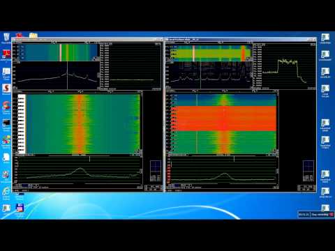
Over on YouTube user Mile Kokotov has uploaded a video showing how he optimizes reception of weak signals in the presence of strong signals on the Airspy software defined radio. He writes:

Using Airspy SDR, I find the interesting way to improve SNR (Signal to Noise Ratio) of the receiving signal, especially in case when very weak signal, which is signal of interest, is close to strong unwanted signals making nonlinear distortion in the receiver front end.

There are two cases:

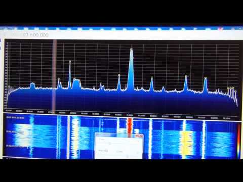
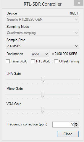
1. If the weak signal frequency is higher than strong unwanted signals, than you can place the weak signal to the left edge of spectrum window, just before the receiving signal levels goes down to the left. Then you can increase the IF-Gain, Mix-Gain and LNA-Gain so you can improve SNR of weak signal without getting nonlinear distortion from the strong signals with lower frequency.

2. If the weak signal frequency is lower than strong unwanted signals, than you can place the weak signal to the right edge of spectrum window, just before the receiving signal levels goes down to the right. Then you can increase the IF-Gain, Mix-Gain and LNA-Gain so you can improve SNR of weak signal without getting nonlinear distortion from the strong signals with higher frequency.

Of course, the best possible way to improve SNR in wide-band receivers sach is Airspy, Funcube, RTL-SDR and others, is by using narrow filter before Airspy front end, but you will loose wide-band possibilities in that way…

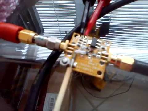
The Wide Dynamic range LNA at the antenna side is strongly recommended for VHF/UHF !

AIRSPY SDR - Tips & Tricks Receiving Weak signals with Strong ones near by

New software rtl_heatmap: Web based waterfall plotter for rtl_power

Over on GitHub a new heatmap plotter for rtl_power has been released. The software is called rtl_heatmap and is software that can be used to create a heatmap from the csv data produced by rtl_power. The software creates the heatmap and also adds frequency marker information to the plot. Rtl_heatmap is written in JS and HTML5 and is a web browser based app.

Rtl_power is a tool that can scan a large chunk of bandwidth with an RTL-SDR dongle and record signal power levels over time.

A demo of the software in action can be found at http://heat.wq.lc/.

rtl_heatmap is a web based heatmap plotter for rtl_power

Building a Simple Downconverter for the RTL-SDR

Over on YouTube Adam Alicajic, seller of the LNA4ALL low noise amplifier has uploaded a video showing how to create a simple downconverter using a 1.3 GHz local oscillator and an LNA4ALL. A downconverter extends the frequency range of the RTL-SDR to frequencies higher than the RTL-SDR’s 1.7 GHz limit.

Adam capacitively connects the 1.3 GHz local oscillator to the input of the LNA4ALL, which causes the input signal to be mixed with the input signal from the antenna. This moves a test 2.8 GHz signal down to 1.5 GHz, which is receivable by the RTL-SDR.

DIY poor guy SDR Downconverter

New SDR# RTL-SDR Driver with LNA/Mixer/VGA Gain Settings and Decimation

A new SDR# driver for the RTL-SDR that comes with manual settings for the LNA/Mixer and VGA gain stages as well as software decimation (in Russian use Google Translate) has been released on rtl-sdr.ru. The three seperate gain stages offer much greater control over optimization of signal SNR and interference management. The decimation feature allows you to sacrifice some bandwidth for increased ADC bit resolution. This means that using the decimation feature can significantly improve the SNR of a signal. Update: It turns out that decimation is already used in the existing SDR# code, so using decimation in the new driver won’t improve the real SNR, only the visible SNR – so there will be no audible improvement. It will however allow you to effectively zoom in on the spectrum without loosing visible resolution. Also it allows you to use a higher sample rate (2.8 MSPS) which will improve SNR, whilst maintaining a reasonably sized (small enough) visible bandwidth for narrowband signals.

The driver is based on Oliver Jowet’s modified driver so it should also have the capability to tune down to 13 MHz or lower. To use the plugin simply download the zip file and copy the files into the SDR# folder, replacing all existing files. Previously we posted about another driver with similar capabilities, but this driver was never released to the public. There was also another driver with just the three gain settings released earlier which this driver appears to be based on.

New RTL-SDR Driver with LNA/Mixer/VGA Gain Settings and Software Decimation

Testing the built in IF Filter on the R820T RTL-SDR

As seen in this previous post, the R820T tuner chip used on most RTL-SDR’s has a built in hardware tunable IF filter. Leif, the programmer of the Linrad SDR software has been experimenting with this filter and has uploaded a video of his experiments to YouTube.

In the video he shows how the R820T IF filter can be set to be as narrow as 300 kHz. Using a narrow IF filter can help to reduce the interference from strong nearby stations by up to 30 dB. Leif uses a modified RTL-SDR driver that comes with Linrad which allows the IF filter to be manually modified.

Update: Leif has posted some extra details in the Osmocom mailing list. He writes that the modified driver can be found at https://github.com/dl8aau/librtlsdr and a Windows version is at https://drive.google.com/file/d/0B9m6SAaGpewQeWtyS0lzdW1xVmM/view?usp=sharing.

R820T with IF filtering

Mods and Performance of an R820T2 RTL-SDR

Over on his blog, RTL-SDR experimenter Laidukas had added a post showing how he modded his R820T2 RTL-SDR for improved noise performance. The mods he applies are:

  • Addition of 100nF, 1nF and 100pF bypass capacitors on the power supply rail.
  • Added a common mode choke to the 5V line.
  • Added a MuRata NFM21 EMI suppression filter to the 5V line.
  • Replaced the oscillator with a 0.3 ppm temperature controlled oscillator (TCXO).
  • Disabled the internal RTL2832U 1.2V switching supply and provided external 3.3V and 1.2V supplies.
  • Replaced the MCX connector with an SMA female connector.
  • Enclosed circuit in a metal box.
Modded R820T2 RTL-SDR Dongle

In addition to the mods, Laidukas also made some measurements on the performance of the R820T2 on some metrics. In the first test he measured the input insertion loss or SWR. He found that the SWR was below 2 between frequencies of 25 MHz to 1076 MHz. At higher frequencies the SWR reached levels up to about 8.

Another test showed that with the LNA disabled the R820T2 had a lower noise floor by about 7dB, when compared to the R820T.

SWR Plot of the RTL-SDR Antenna Input
SWR Plot of the RTL-SDR Antenna Input with LNA disabled