AERO is essentially the satellite based version of aircraft ACARS. AERO's L-band signals contains short ground to air messages with things like weather reports and flight plans. The C-band signals are the air to ground portion of AERO and more difficult to receive as they require an LNB and large dish. However they are much more interesting as they contain flight position data, like ADS-B.
Over on YouTube Tomasz Haddad has uploaded a video of C-band AERO being received from the Inmarsat 3 F2 (Atlantic Ocean Region – East (AOR-E) 15W satellite. He uses a 1.80m motorized satellite dish with Kaonsat KS-N201G C-band LNB, a Prof 7301 PCI satellite card (to power the LNB) and an RTL-SDR V3. The C-band LNB translates the high C-band frequencies down to L-band which is receivable with an RTL-SDR. He notes that the LNB drifts quite a lot as it is not frequency stabilized.
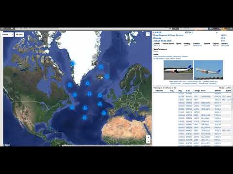
With the signals received by his setup he's able to use the JAERO decoding software together with Virtual Radar Server to plot aircraft positional data using Virtual Radar Server. The plotted aircraft are mostly all in the middle of the ocean or in remote areas, which is where C-band AERO is normally used due to the lack of ground ADS-B stations.
Inmarsat 3 F2 15W C Band AERO Reception Using Jaero And Virtual Radar
In the past the Outernet project operated on L-band frequencies, and for the service they manufactured a number of active L-band active ceramic patch antennas for use with RTL-SDR dongles. Outernet has since moved on to faster Ku-band delivery, and hence their old L-band antennas can no longer be used for their service. There are a few of these patch antennas left over in Outernet's stock and they are currently selling them on eBay for US $29 + shipping (link expired).
Although no longer useful for Outernet, these antennas are still very useful for receiving other L-band services such as STD-C SafetyNET and AERO. SafetyNET is a text broadcast intended for sailors at sea, but contains many interesting and potentially useful messages for others too. Often they transmit data like military sea live firing warnings, reports of marine pirate activity, search and rescue reports, scientific vessel reports as well as weather reports. AERO is the satellite version of ACARS, and is used by aircraft to communicate with text messages to and from ground stations. L-Band AERO signals only contain information from the ground station up to the aircraft. For air to ground you'll need a C-band receiver set up. AERO is the satellite communications protocol that was so heavily centered on during the MH370 flight disappearance investigation.
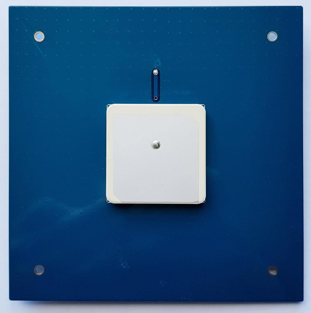
In the past we've reviewed the Outernet L-band ceramic patch and found it to work very well. Certainly STD-C and AERO signals are easy to receive with the antenna if you point it at the satellite. The antenna requires bias tee power and can easily be used in combination with the bias tee on our RTL-SDR V3 dongles. The onboard filter helps reduce problems from interfering signals, but restricts reception to 1525 - 1559 MHz, so Iridium signals cannot be received with this antenna.
The L-Band Active and Filtered Ceramic Patch Antenna.
Thanks to Manuel a.k.a. Tysonpower for submitting his latest YouTube video tutorial about building an 1550 MHz L-band LHCP helical antenna for receiving satellite signals such as Inmarsat, AERO and HRPT.
Manuel's design is based on a 3D printed part which is used to accurately form the helical winding. The winding then mounts onto an aluminum plate and a satellite dish arm using a custom 3D printed adapter for the dish arm. In the video he uses the helical feed with an 80cm satellite dish and a standard 40mm LNB mount on the dish arm. Attached to the feed are two LNAs in series which help to lower the noise figure and reduce losses in the coax cable.
With this setup he writes that he was able to get very good AERO and Outernet reception from Alphasat (25E geostationary). He also writes that he's had good results using it for HRPT reception as well.
The 3D printing STL files and list of parts required are available on Thingiverse, and the companion video is shown below. Note that the video is narrated in German, but English subtitles are available.
[EN subs] LHCP Helix L-Band Feed - 3D Druck für eine genaue Helix
Recently the Outernet project transitioned from using RTL-SDR dongles and C.H.I.P single board computers to using their Dreamcatcher board, which is an RTL-SDR and computing board all in one. In between the transition they also produced a number of ‘SDRx’ dongles. These were custom RTL-SDR dongles with a built in L-band LNA and filter. As they no longer need the SDRx they have them on clearance at their store.
The clearance price is $15 USD which is an excellent deal. Remember though, that the SDRx is limited in frequency range – it is designed for receiving L-band satellites between 1525 – 1559 MHz and the filter will cut off all other frequencies.
The Outernet SDRx on Clearance
Just add a simple L-band tuned antenna to the port and you should be able to receive Inmarsat and a signal like STD-C, AERO or the Outernet signal. A suitable antenna might be a homebrew patch, helix, cooking pot antenna or even a small tuned V-dipole antenna can work for the stronger AERO signals.
We also see that the price of their L-band Outernet active ceramic patch antenna has been dropped down slightly to $25 USD. This antenna is bias tee powered and can be used with a V3 dongle or their Dreamcatcher hardware. The Dreamcatcher itself is also now reduced in price to $59 USD.
We have a review of the Dreamcatcher and active ceramic patch antenna available here.
Outernet Dreamcatcher and L-Band Active Ceramic Patch
We also now list Outernet products in our store. These are commission sales so we receive a little bit per purchase which supports the blog, and the items are shipped by Outernet within the USA.
If you were unaware, Outernet is a free L-band based satellite service that provides content such as news, weather data, APRS repeats and more. Currently you can get about 20MB of data a day. Outernet receivers are also all based around the RTL-SDR, allowing for very cheap receivers to be built
Over on his YouTube channel Adam 9A4QV has uploaded a new video showing reception of L-band signals with a bias tee powered LNA4ALL and a small patch antenna. The video seems to show a new miniature bias tee powered LNA4ALL device that Adam might be working on. The LNA4ALL is a low noise amplifier that works well with our bias tee capable RTL-SDR dongles.
The patch antenna is made out of a single piece of PCB board which was made by etching out the patch pattern with masking tape. While the patch antenna is not optimal, and tested indoors, Adam is still able to receive some AERO signals.
Later in the video he compares the PCB patch against a GPS patch antenna which gets no reception. He also compares the results when two LNA4ALL’s are used in series. Using two LNA’s improves reception slightly.
Recently we posted news that Outernet had released their 1.5 GHz LNA, Patch Antenna and E4000 Elonics RTL-SDR + E4000/LNA Bundle. When used together, the products can be used to receive the Outernet L-band satellite signal, as well as other decodable L-band satellite signals like AERO and Inmarsat STD-C EGC. Outernet is a new satellite service that aims to be a free “library in the sky”. They continuously broadcast services such as news, weather, videos and other files from satellites.
EDIT: For international buyers the Outernet store has now started selling these products at http://store.outernet.is.
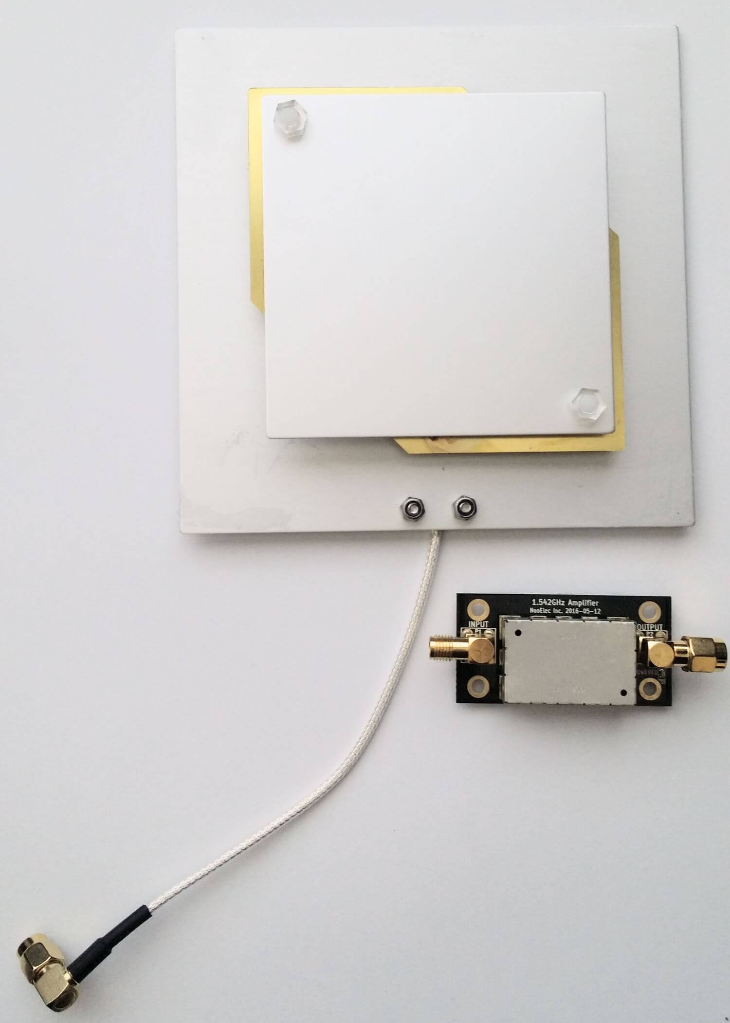
A few days ago we received the LNA and patch antenna for review. The patch antenna is similar to the one we received a while ago when writing our STD-C EGC tutorial, although this one is now slightly larger. It is roughly 12 x 12 cm in size, 100g heavy and comes with about 13 cm of high quality RG316 coax cable with a right angled SMA male connector on the end. The coax cable is clamped on the back for effective strain relief.
The Outernet patch antenna and LNA
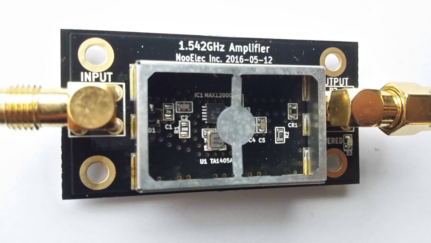
The LNA is manufactured by NooElec for Outernet. It amplifies with 34 dB gain from 1525 – 1559 MHz, with its center frequency at 1542 MHz. It must be powered via a 3 – 5.5V bias tee and draws 25 mA. The package consists of a 5 x 2.5 cm PCB board with one female and one male SMA connector. The components are protected by a shielding can. Inside the shielding can we see a MAX12000 LNA chip along with a TA1405A SAW filter. The MAX12000 (datasheet here) is an LNA designed for GPS applications and has a NF of 1 dB. It has a design where there are two amplifiers embedded within the chip, and it allows you to connect a SAW filter in between them. The TA1405A SAW filter appears to be produced by Golledge (datasheet here), and it has about a 3 dB insertion loss.
The Outernet L-Band LNAInside the Outernet LNA
We tested the patch and LNA together with one of our V3 RTL-SDR Blog dongles, with the bias tee turned on. The LNA was connected directly to the dongle, with no coax in between. The patch antenna was angled to point towards the Inmarsat satellite. A 5 meter USB extension cord was then used to interface with a PC. The images below demonstrate the performance we were able to get.
The Outernet team writes that a SNR level of only 2 dB is needed for decoding to work on their signal. With the patch and LNA we were able to get at least 12 dB so this is more than good enough. Other signals such as AERO and STD-C EGC also came in very strongly. Even when not angled at the satellite and placed flat on a table it was able to receive the signal with about 5 dB’s of SNR.
In conclusion the patch and LNA worked very well at receiving the Outernet signal as well as AERO and STD-C EGC. We think these products are great value for money if you are interested in these L-Band signals, and they make it very easy to receive. The only minor problem with the patch antenna is that there is no stand for it, which makes it difficult to mount in a way that faces the satellite. However this issue can easily be fixed with some sellotape and your own mount.
In the future once the Outernet Rpi3 OS and decoder image is released we hope to show a demonstration and tutorial on receiving Outernet data.
AERO is essentially the satellite based version of aircraft ACARS. AERO's L-band signals contains short ground to air messages with things like weather reports and flight plans. The C-band signals are the air to ground portion of AERO and more difficult to receive as they require an LNB and large dish. However they are much more interesting as they contain flight position data, like ADS-B.
Over on YouTube Tomasz Haddad has uploaded a video of C-band AERO being received from the Inmarsat 3 F2 (Atlantic Ocean Region – East (AOR-E) 15W satellite. He uses a 1.80m motorized satellite dish with Kaonsat KS-N201G C-band LNB, a Prof 7301 PCI satellite card (to power the LNB) and an RTL-SDR V3. The C-band LNB translates the high C-band frequencies down to L-band which is receivable with an RTL-SDR. He notes that the LNB drifts quite a lot as it is not frequency stabilized.
With the signals received by his setup he's able to use the JAERO decoding software together with Virtual Radar Server to plot aircraft positional data using Virtual Radar Server. The plotted aircraft are mostly all in the middle of the ocean or in remote areas, which is where C-band AERO is normally used due to the lack of ground ADS-B stations.
Inmarsat 3 F2 15W C Band AERO Reception Using Jaero And Virtual Radar
In the past the Outernet project operated on L-band frequencies, and for the service they manufactured a number of active L-band active ceramic patch antennas for use with RTL-SDR dongles. Outernet has since moved on to faster Ku-band delivery, and hence their old L-band antennas can no longer be used for their service. There are a few of these patch antennas left over in Outernet's stock and they are currently selling them on eBay for US $29 + shipping (link expired).
Although no longer useful for Outernet, these antennas are still very useful for receiving other L-band services such as STD-C SafetyNET and AERO. SafetyNET is a text broadcast intended for sailors at sea, but contains many interesting and potentially useful messages for others too. Often they transmit data like military sea live firing warnings, reports of marine pirate activity, search and rescue reports, scientific vessel reports as well as weather reports. AERO is the satellite version of ACARS, and is used by aircraft to communicate with text messages to and from ground stations. L-Band AERO signals only contain information from the ground station up to the aircraft. For air to ground you'll need a C-band receiver set up. AERO is the satellite communications protocol that was so heavily centered on during the MH370 flight disappearance investigation.
In the past we've reviewed the Outernet L-band ceramic patch and found it to work very well. Certainly STD-C and AERO signals are easy to receive with the antenna if you point it at the satellite. The antenna requires bias tee power and can easily be used in combination with the bias tee on our RTL-SDR V3 dongles. The onboard filter helps reduce problems from interfering signals, but restricts reception to 1525 - 1559 MHz, so Iridium signals cannot be received with this antenna.
The L-Band Active and Filtered Ceramic Patch Antenna.
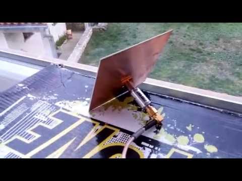
Thanks to Manuel a.k.a. Tysonpower for submitting his latest YouTube video tutorial about building an 1550 MHz L-band LHCP helical antenna for receiving satellite signals such as Inmarsat, AERO and HRPT.
Manuel's design is based on a 3D printed part which is used to accurately form the helical winding. The winding then mounts onto an aluminum plate and a satellite dish arm using a custom 3D printed adapter for the dish arm. In the video he uses the helical feed with an 80cm satellite dish and a standard 40mm LNB mount on the dish arm. Attached to the feed are two LNAs in series which help to lower the noise figure and reduce losses in the coax cable.
With this setup he writes that he was able to get very good AERO and Outernet reception from Alphasat (25E geostationary). He also writes that he's had good results using it for HRPT reception as well.
The 3D printing STL files and list of parts required are available on Thingiverse, and the companion video is shown below. Note that the video is narrated in German, but English subtitles are available.
[EN subs] LHCP Helix L-Band Feed - 3D Druck für eine genaue Helix
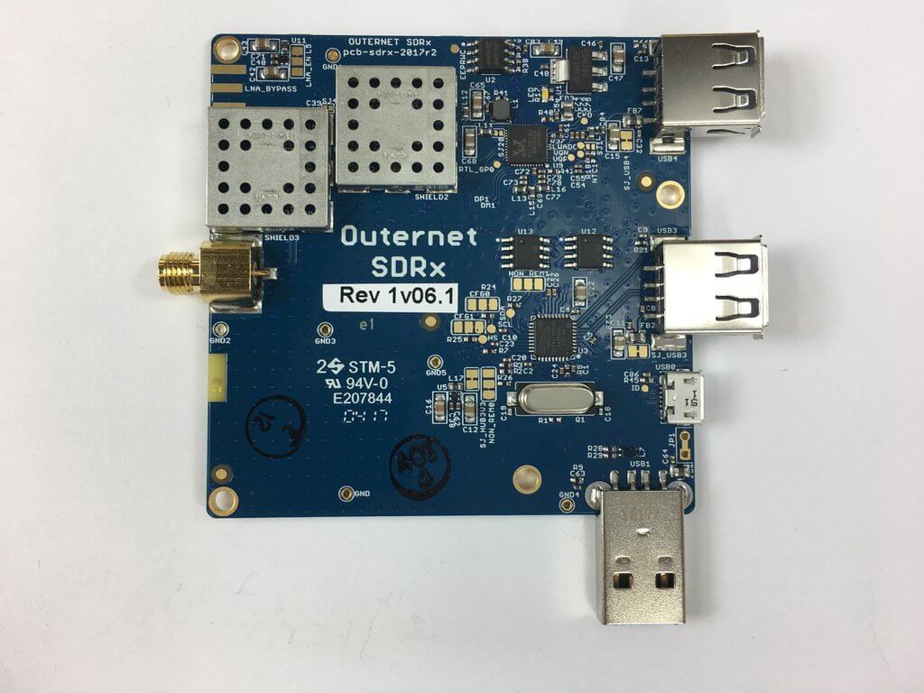
Recently the Outernet project transitioned from using RTL-SDR dongles and C.H.I.P single board computers to using their Dreamcatcher board, which is an RTL-SDR and computing board all in one. In between the transition they also produced a number of ‘SDRx’ dongles. These were custom RTL-SDR dongles with a built in L-band LNA and filter. As they no longer need the SDRx they have them on clearance at their store.
The clearance price is $15 USD which is an excellent deal. Remember though, that the SDRx is limited in frequency range – it is designed for receiving L-band satellites between 1525 – 1559 MHz and the filter will cut off all other frequencies.
The Outernet SDRx on Clearance
Just add a simple L-band tuned antenna to the port and you should be able to receive Inmarsat and a signal like STD-C, AERO or the Outernet signal. A suitable antenna might be a homebrew patch, helix, cooking pot antenna or even a small tuned V-dipole antenna can work for the stronger AERO signals.
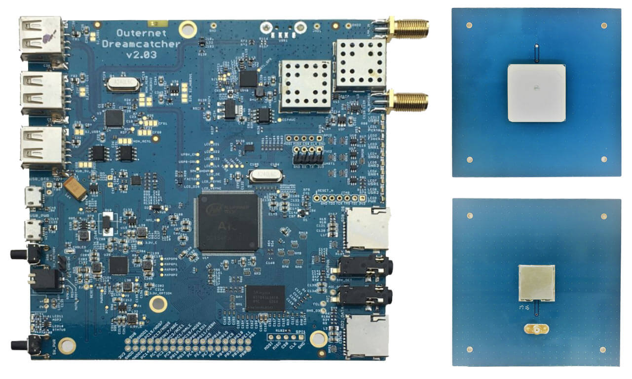
We also see that the price of their L-band Outernet active ceramic patch antenna has been dropped down slightly to $25 USD. This antenna is bias tee powered and can be used with a V3 dongle or their Dreamcatcher hardware. The Dreamcatcher itself is also now reduced in price to $59 USD.
We have a review of the Dreamcatcher and active ceramic patch antenna available here.
Outernet Dreamcatcher and L-Band Active Ceramic Patch
We also now list Outernet products in our store. These are commission sales so we receive a little bit per purchase which supports the blog, and the items are shipped by Outernet within the USA.
If you were unaware, Outernet is a free L-band based satellite service that provides content such as news, weather data, APRS repeats and more. Currently you can get about 20MB of data a day. Outernet receivers are also all based around the RTL-SDR, allowing for very cheap receivers to be built
Over on his YouTube channel Adam 9A4QV has uploaded a new video showing reception of L-band signals with a bias tee powered LNA4ALL and a small patch antenna. The video seems to show a new miniature bias tee powered LNA4ALL device that Adam might be working on. The LNA4ALL is a low noise amplifier that works well with our bias tee capable RTL-SDR dongles.
The patch antenna is made out of a single piece of PCB board which was made by etching out the patch pattern with masking tape. While the patch antenna is not optimal, and tested indoors, Adam is still able to receive some AERO signals.
Later in the video he compares the PCB patch against a GPS patch antenna which gets no reception. He also compares the results when two LNA4ALL’s are used in series. Using two LNA’s improves reception slightly.
Recently we posted news that Outernet had released their 1.5 GHz LNA, Patch Antenna and E4000 Elonics RTL-SDR + E4000/LNA Bundle. When used together, the products can be used to receive the Outernet L-band satellite signal, as well as other decodable L-band satellite signals like AERO and Inmarsat STD-C EGC. Outernet is a new satellite service that aims to be a free “library in the sky”. They continuously broadcast services such as news, weather, videos and other files from satellites.
EDIT: For international buyers the Outernet store has now started selling these products at http://store.outernet.is.
A few days ago we received the LNA and patch antenna for review. The patch antenna is similar to the one we received a while ago when writing our STD-C EGC tutorial, although this one is now slightly larger. It is roughly 12 x 12 cm in size, 100g heavy and comes with about 13 cm of high quality RG316 coax cable with a right angled SMA male connector on the end. The coax cable is clamped on the back for effective strain relief.
The Outernet patch antenna and LNA
The LNA is manufactured by NooElec for Outernet. It amplifies with 34 dB gain from 1525 – 1559 MHz, with its center frequency at 1542 MHz. It must be powered via a 3 – 5.5V bias tee and draws 25 mA. The package consists of a 5 x 2.5 cm PCB board with one female and one male SMA connector. The components are protected by a shielding can. Inside the shielding can we see a MAX12000 LNA chip along with a TA1405A SAW filter. The MAX12000 (datasheet here) is an LNA designed for GPS applications and has a NF of 1 dB. It has a design where there are two amplifiers embedded within the chip, and it allows you to connect a SAW filter in between them. The TA1405A SAW filter appears to be produced by Golledge (datasheet here), and it has about a 3 dB insertion loss.
The Outernet L-Band LNAInside the Outernet LNA
We tested the patch and LNA together with one of our V3 RTL-SDR Blog dongles, with the bias tee turned on. The LNA was connected directly to the dongle, with no coax in between. The patch antenna was angled to point towards the Inmarsat satellite. A 5 meter USB extension cord was then used to interface with a PC. The images below demonstrate the performance we were able to get.
The Outernet team writes that a SNR level of only 2 dB is needed for decoding to work on their signal. With the patch and LNA we were able to get at least 12 dB so this is more than good enough. Other signals such as AERO and STD-C EGC also came in very strongly. Even when not angled at the satellite and placed flat on a table it was able to receive the signal with about 5 dB’s of SNR.
In conclusion the patch and LNA worked very well at receiving the Outernet signal as well as AERO and STD-C EGC. We think these products are great value for money if you are interested in these L-Band signals, and they make it very easy to receive. The only minor problem with the patch antenna is that there is no stand for it, which makes it difficult to mount in a way that faces the satellite. However this issue can easily be fixed with some sellotape and your own mount.
In the future once the Outernet Rpi3 OS and decoder image is released we hope to show a demonstration and tutorial on receiving Outernet data.
Outernet are a startup company that hope to revolutionize the way people in regions with no, poor or censored internet connectivity receive information. Their service is downlink only, and runs on C and L-band satellite signals, beaming up to date news as well as other information like books, educational videos and files daily. To receive it you will need one of their official or homemade versions of the Lighthouse or Lantern receivers (the latter of which is still to be released), or an RTL-SDR or similar SDR. Recently they began test broadcasts of their new 5 kHz 1539.8725 MHz L-band signal on Inmarsat I4F3 located at 98W (covers the Americas), and they hope to begin broadcasts in more regions soon too.
The typical RTL-SDR is known to often have poor or failing performance above 1.5 GHz (though this can be fixed to some extent), so Outernet have been working on an L-band downconverter. A downconverter works by receiving signals, and shifting them down to a lower frequency. This is advantageous because the RTL-SDR is more sensitive and does not fail at lower frequencies, and if used close to the antenna, the lower frequency allows longer runs of cheap coax cable to be used without significant signal loss.
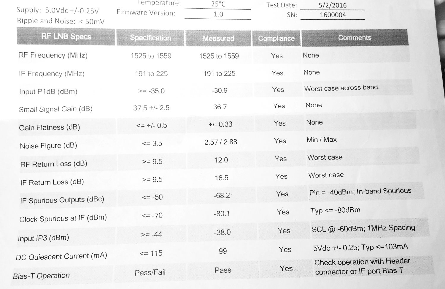
Earlier this week we received in the mail a prototype of their downconverter. The downconverter uses a 1.750 GHz LO signal, so any signal input into it will be subtracted from this frequency. For example the STD-C frequency of 1.541450 GHz will be reduced to 1750 MHz – 1541.450 MHz = 208.55 MHz. This also means that the spectrum will appear reversed, but this can be corrected by selecting “Swap I & Q” in SDR#. The downconverter also amplifies the signal with an LNA, and has a filter to remove interfering out of band signals.
The prototype Outernet downconverter circuit board.Specsheet for the downconverter.
We tested the downconverter using their patch antenna which they had sent to us at an earlier date (the patch antenna is used and shown in this Inmarsat STD-C reception tutorial). Our testing found that overall the downconverter works extremely well, giving us much better signal levels. Previously, we had used the patch + LNA4ALL and were able to get reception good enough to decode STD-C and AERO signals, but with the requirement that the patch be carefully pointed at the satellite for maximum signal. With the downconverter the signals come in much stronger, and accurate pointing of the patch is no longer required to get a signal strong enough to decode STD-C or AERO.
The downconverter can be powered by a bias tee connection, and this works well with our bias tee enabled RTL-SDR dongles. We also tested with the bias tee on the Airspy R2 and Mini and had no problems. It can also be powered with a direct 5V connection to a header, and they note that the header will be replaced by a USB connector in the production version.
The release date and exact price that these will be sold at is not confirmed, but we believe that it will be priced similarly to upconverters at around $50 USD or less. A good low cost downconverter should help RTL-SDR and other SDR users receive not only the Outernet signal better, but also other satellite signals such as STD-C and AERO. Although the input is filtered and the RF frequency is specified at 1525 to 1559 MHz, we had no trouble receiving signals up to GPS frequencies of 1575 MHz, and even up to Iridium signals at 1.626 GHz, though reception was much weaker up that high.
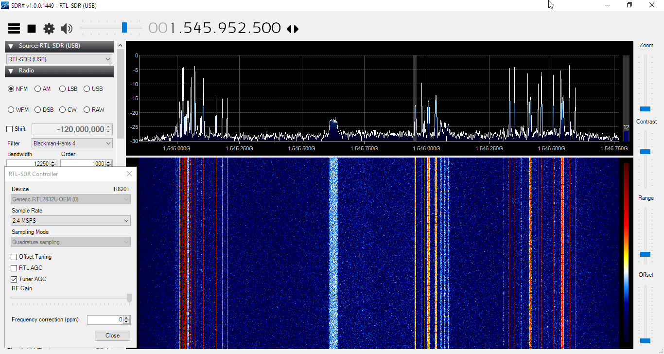
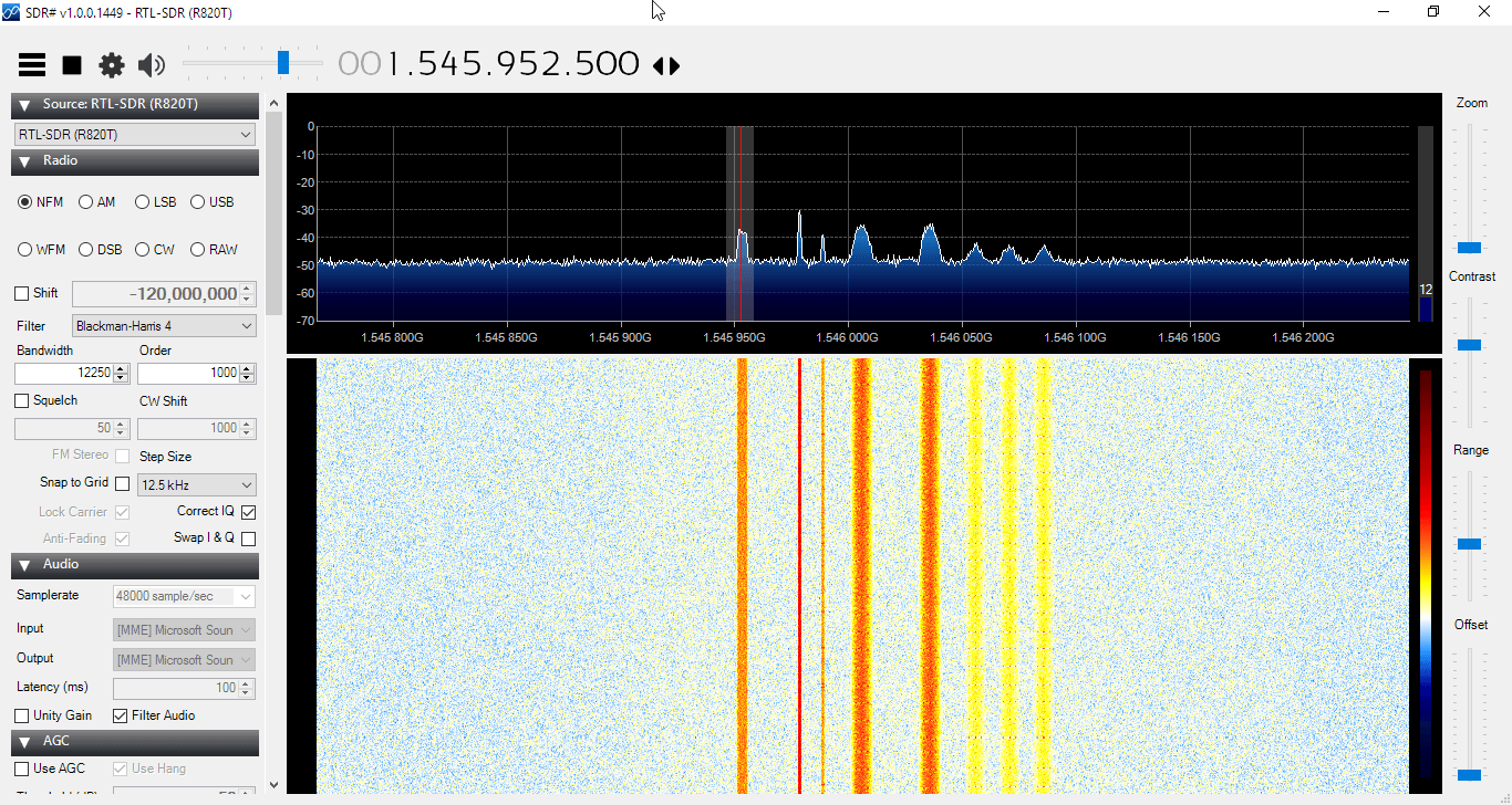
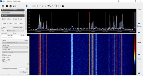
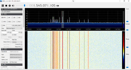
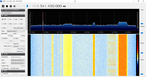
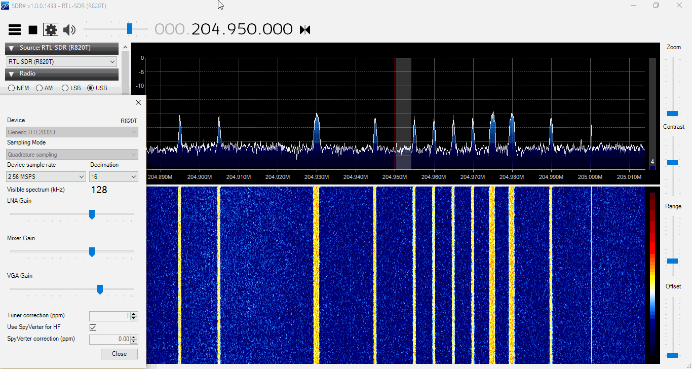
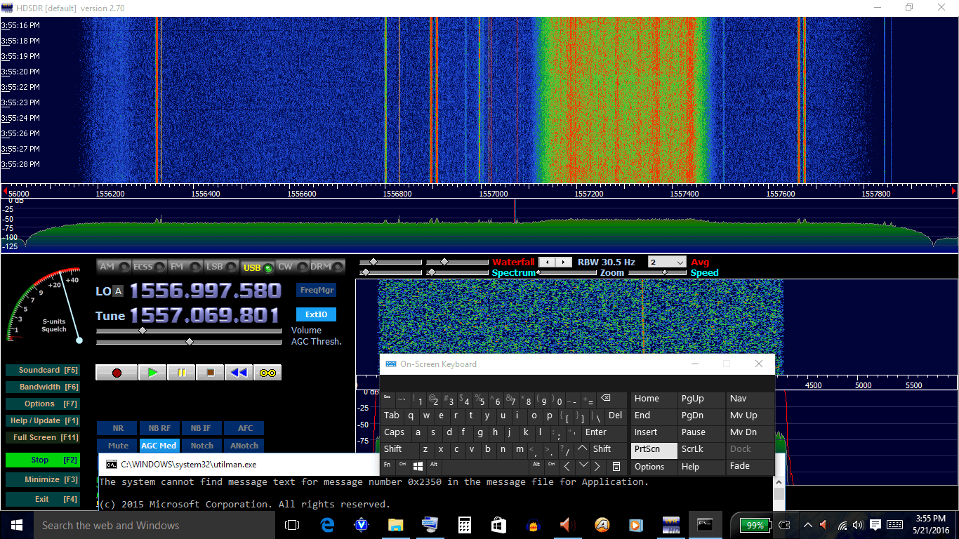
Below are some screenshots of reception. Here we used the Outernet patch antenna sitting in a windowsill with the downconverter directly after the antenna, and then 10 meters of RG6 coax cable to the PC and bias tee enabled RTL-SDR. We found that with the downconverted ~200 MHz signal the loss in the RG6 coax was negligible. Better reception could be obtained by putting the patch outdoors. In some screenshots we used Vasilli’s R820T driver with the decimation feature, which allows you to zoom into narrowband signals much more clearly.
Some AERO Signals Zoomed in with the Decimation feature in SDR#. Received with the Outernet downconverter and patch antenna.Some AERO and other Signals Zoomed in with the Decimation feature in SDR#. Received with the Outernet downconverter and patch antenna.Signals zoomed out. Received with the Outernet downconverter and patch antenna.
His results show that the dish outperforms the helix antennas by a significant amount, but only once he took it outdoors. The 10-turn helix antenna also worked better than the tin can helix, although he found that it required very accurate pointing.
Inmarsat are geostaionary satellites that transmit signals on L-band at around 1.5 GHz. They transmit signals that can be decoded with an RTL-SDR, such as STD-C EGC (weather, messaging and safety messages for boats), as well as AERO (the satellite version of ACARS for aircraft).
![[EN subs] LHCP Helix L-Band Feed - 3D Druck für eine genaue Helix](https://www.rtl-sdr.com/wp-content/plugins/wp-youtube-lyte/lyteCache.php?origThumbUrl=https%3A%2F%2Fi.ytimg.com%2Fvi%2FkNuf8zcLdHk%2F0.jpg)