Tagged: rtl-sdr

Radio Astronomy Tool rtl_power_fftw Updated

The rtl_power program allows you to use the RTL-SDR to perform a power scan over an arbitrarily large portion of the frequency spectrum (within the RTL-SDR’s supported frequency range) by hopping over ~2 MHz swaths of bandwidth. The updated rtl_power_fftw software was originally written by Klemen Blokar and Andrej Lajovic and is an update over the regular rtl_power program. It uses a faster FFT processing algorithm and has several other enhancements that make it more useful for radio astronomy purposes.

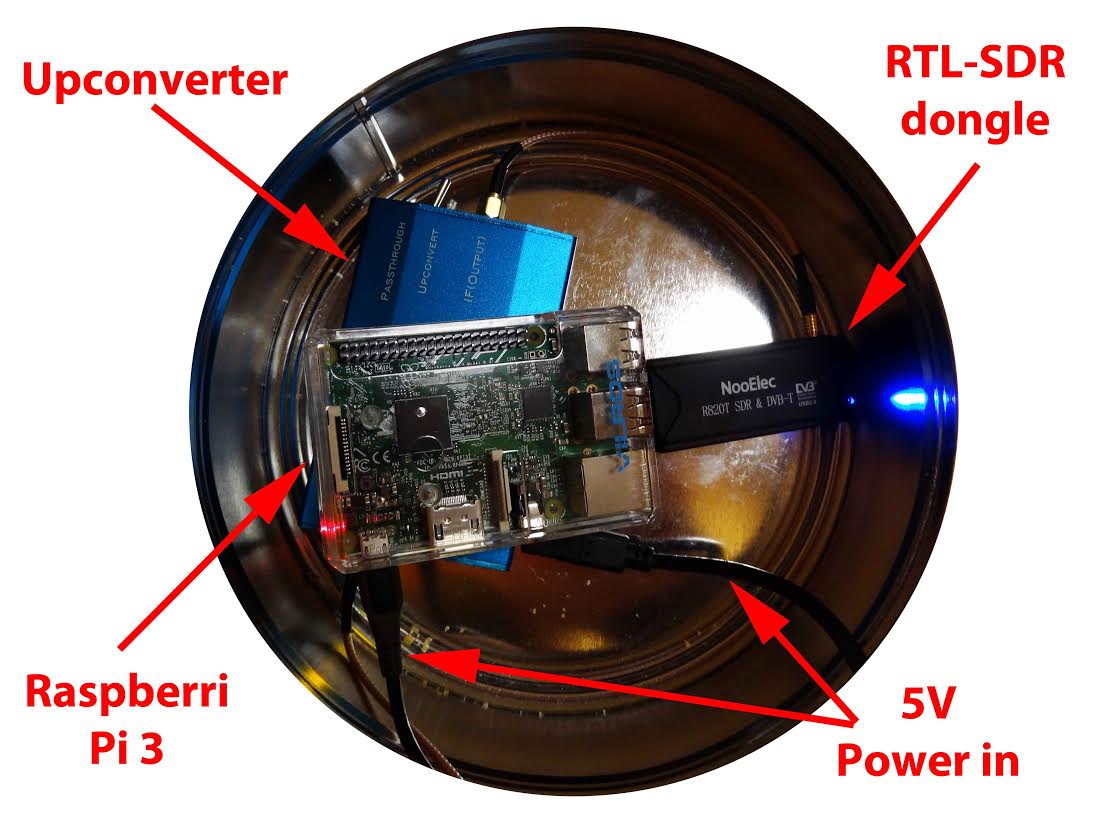
Recently Mario Cannistrà has released a new version of rtl_power_fftw which has several additional improvements applied. He intends to use it in his RTL-SDR based radio astronomy IoT project which is presented on his Hackster.io blog. He writes:

I added the following command line parameters:

  • -e param for session duration
    this allows to specify the recording duration in sec, mins… etc just like it was possible with rtl-power
  • -q flag to limit verbosity
    this will allow the various printouts to happen only the first time and not on every scan
  • -m param to produce binary matrix output and separate metadata file
    this will get a file name (no extension) and use it to store the power values in binary format within a .bin file + a metadata text file with .met extension

Summary of my requirements:

  • I wanted to leverage the ability of rtl-power-fftw to specify N average values to integrate for less than 1 second when needed. Plus running multi-MHz scans and storing for several minutes.
  • I wanted to use a binary format instead of the .csv one in order to obtain the smallest possible size since I’m logging all the night long (CSV’s blank delimiters and decimal dots were wasting my precious microSD space)
  • keep high the precision on decimal digits saving float values (could be important for other usages)
  • obtain a complete stream of binary values representing all the bins for each scan, one scan after the other, in a matrix like organization
  • …that would allow me to plot the waterfall extremely fast with gnuplot
  • …and then add specific annotations and file properties/metadata in a more convenient way using python
Example rtl_power_fftw output: A scan of Jupiter's radio emissions.
Example rtl_power_fftw output: A scan of Jupiter’s radio emissions.

FlightAware ProStick: A new ADS-B optimized RTL-SDR with built in LNA

The FlightAware team have today announced the release of the "ProStick", an RTL-SDR dongle that they write has been modified for improved ADS-B reception. The new FlightAware RTL-SDR's main defining feature is that it comes with a built in low noise amplifier (LNA) on the front end. The built in LNA is optimized for the ADS-B frequency of 1090 MHz and has 19 dB of gain with a 0.4 dB noise figure and an OIP3 of +39dB. They claim that the new unit will give a 20-100% performance boost in terms of range for Mode S reception when compared to a standard RTL-SDR.

As the increased gain and amplifier non-linearities can cause overload and intermodulation to more easily occur, the FlightAware team stresses that you must use the new device with a 1090 MHz filter, such as their FlightAware filter. In a previous post we reviewed the FlightAware filter and antenna and found that they performed very well and are great value for money.

The new unit is priced cheaply at $16.95 + shipping on Amazon for US buyers, and $24.95 + shipping on eBay for international buyers.

So far we haven't seen any circuit photos or news about which LNA chip has been used, but we intend buy a unit and do a review when it arrives.

One criticism about this unit that we can already see is that it should be understood that good RF design teaches us to always place the LNA as close to the antenna as possible to overcome cable loss and keep the noise figure low. Placing the LNA at the antenna vs at the receiver makes a huge difference in performance, depending on how long and lossy your coax cable run is. Furthermore, integrating an LNA into the receiver ruins the system for optimal performance with an LNA placed by the antenna due to the reduced linearity caused by the additional internal LNA. The post at http://ava.upuaut.net/?p=836 explains optimal LNA placement very well. We think that perhaps selling an external LNA and bias tee module would have been a significantly better idea to optimize ADS-B reception. However, the additional LNA should help to reduce the noise figure of the dongle by a few dBs which will result in improved ADS-B reception as long as signal saturation does not occur. 

The new FlightAware ADS-B optimized RTL-SDR.
The new FlightAware dongle running on a PiAware Raspberry Pi system.
The new FlightAware dongle running on a PiAware Raspberry Pi system (actual unit uses SMA).

Meteor M-N2 now active again

According to various reports the Russian Meteor M-N2 satellite appears to be active again once more. The Meteor M N-2 is a polar orbiting Russian weather satellite that was launched in July 2014. It transmits with the LRPT protocol which allows us to receive weather satellite images with an RTL-SDR that are of a much higher resolution than the NOAA APT satellites. 

Unfortunately late last year Meteor M N-2 had some problems and LRPT transmissions were turned off for the time being. During this downtime the Russian space agency switched the LRPT transmitter on the older Meteor M N-1 satellite back on, even though the satellite was tumbling in orbit. Currently people are not reporting any signal from Meteor M N-1, so this may have been turned off, perhaps temporarily.

Now however, it seems that Meteor M N-2 has been switched back on again and various people have already successfully received its signal. If you want to receive these Meteor M N-2 weather images with an RTL-SDR dongle or other SDR then you can view the tutorial written by Happysat here.

Another Sample LRPT Image
A Sample LRPT Image from Meteor M N-2

Building a 28.8 MHz TCXO for the RTL-SDR

For accurate frequency tuning even amongst large temperature in an SDR, a Temperature Compensated Crystal Oscillator (TCXO) should be used as the main oscillator. Standard RTL-SDR dongles used a frequency of 28.8 MHz and do not come with a TCXO, but for some time now we have been selling our own branded dongles that come with a TCXO built in (out of stock at the moment sorry – back in the first half of April!). If you have an older or other dongle that does not have a TCXO it can be an interesting exercise to hack one in yourself. The biggest problem though, is that 28.8MHz TCXO oscillators are not commonly found for sale in low quantities.

Over on YouTube user devttys0 (Craig) has uploaded a video that thoroughly explains the theory behind creating a home brew 28.8 MHz TCXO out of a standard non-temperature controlled 19.2 MHz oscillator. The build involves halving the frequency, and then filtering and using the third harmonic as the clock signal (19.2/2 * 3 = 28.8 MHz), as well as creating the temperature compensation circuitry.

On his blog Craig has also uploaded schematics and a frequency temperature curve he measured from his home brew TCXO.

If you wanted to make something a little easier to build then we recommend looking at our previous post which shows how an experimenter used an SI5351A voltage controlled oscillator on the RTL-SDR.

A GNU Radio Based ISDB-T and RTL-SDR Compatible 1Seg Decoder

In most parts of the world the DVB-T standard is used to air digital HDTV. In the USA the ATSC standard is used, and in China DTMB is used instead. In other countries such as Brazil, Peru, Argentina, Chile, Honduras, Venezuela, Ecuador, Costa Rica, Paraguay, Philippines, Bolivia, Nicaragua and Uruguay a third standard called “ISDB-T International” is used which is based on the Japanese ISDB-T standard. 

Digital broadcast standards used in each country.

Recently a team from Uruguay has been working on creating a ISDB-T receiver in GNU Radio. With this decoder ISDB-T signals can be received with a wide bandwidth SDR (needs to be 6MHz or larger) and then decoded into a video file. Because ISDB-T is so similar to DVB-T they have based much of their code on gr-dvbt which is a GNU Radio based DVB-T decoder.

In addition to the ISDB-T decoder, they have also implemented a 1-seg decoder. 1-seg is a mobile HDTV service that exists in Japan, Argentina, Brazil, Chile, Uruguay and Peru. It runs on the ISDB-T system, and is called “1-seg” because it’s data occupies 1-segment of the 13-segment based ISDB-T bandwidth. It is used in small mobile TV receivers, many of which are now built directly into mobile phones sold in countries that use ISDB-T. Due to it’s much lower bandwidth requirement the 1-seg decoder can be used with an RTL-SDR dongle, and has already been tested to work.

A typical 1-seg capable Japanese mobile phone receiving digital mobile TV.
A typical 1-seg capable Japanese mobile phone receiving digital mobile TV. With the GNU Radio 1-seg decoder these transmissions can be received with an RTL-SDR.

Inspectrum: A New Tool for Analysing Captured Signals

Inspectrum is a Linux and OSX based tool that can be used for analysing captured signals. It is compatible with the IQ files generated from SDRs, such as the RTL-SDR or HackRF.

Over on YouTube user Mike has uploaded a video that demo’s the latest version of Inspectrum. He shows how the tool can be used to quickly browse the waveforms in a captured signal and how it can be used to determine various digital binary signal properties through an overlay that can be dragged to match the bit frequency of the captured signal.

This program looks like it is shaping up to be a very useful tool for those interested in reverse engineering digital signals. The Inspectrum code and installation procedure can be found at https://github.com/miek/inspectrum.

inspectrum tuner demo

RTLSDR4Everyone: Raspberry Pi guide & choosing your first dongle

Over on his blog rtlsdr4everyone author Akos has recently uploaded three new posts. The first post is about the Raspberry Pi minicomputer and the post discusses the merits of using the Raspberry Pi with an RTL-SDR dongle. The second post provides information to help people new to RTL-SDR choose their first dongle, and weighs up options between dongles that cost $10, $20, $25, $35 and $50 dollars. Finally, the third post compares two dongles on HF performance.

Raspberry Pi3 and RTL-SDR dongles.

Creating a FSK SSDV data system for High Altitude Balloons

David and Mark are building a 115 kbit/s FSK SSDV (slow scan digital video) data system for high altitude balloons. In their system, on the balloon transmit side they use a Raspberry Pi, Raspberry Pi camera and a RFM22B wireless transceiver modulator board to transmit the SSDV FSK signal. On the receive side they use an RTL-SDR dongle, low noise preamplifier and a GNU Radio program to demodulate the SSDV images. The first video below demonstrates the hardware and GNU Radio program and shows them receiving the SSDV signal. In the second video they demonstrate that the images can be received at low signal levels (-106dBm) as well, by heavily attenuating the signal.

115.2kbaud FSK Modem Test

115.387kbaud FSK Modem Test - Part 2

If you are interested, all their code for the SSDV system has been uploaded to https://github.com/projecthorus/HorusHighSpeed.

While testing the RTL-SDR for use in this system they also measured the noise figure of an R820T RTL-SDR dongle. The noise figure at maximum gain comes out at around 5.6 dB. By adding a low noise amplifier they reduce the measured noise figure down to 2 dB.

Testing the attenuated SSDV signal reception with an RTL-SDR.