Tagged: rtl-sdr

SDR4Everyone: Review of the HackRF

Over on his ‘SDR4Everyone’ blog author Akos has recently uploaded a new post that reviews the HackRF One, and also compares it against the SDRplay RSP and RTL-SDR. In his review he discusses his first impressions of the HackRF, his concerns about it being labelled as a transceiver, and some of its various features. He also does a screenshot comparison of the HackRF, RSP and RTL-SDR on shortwave reception and image rejection performance. Akos also notes that there are not many applications in the high gigahertz range that cannot be done with cheaper or more specialized equipment. Finally he concludes that the HackRF is not very sensitive or good at RX in general, but still has enough features to make it a worthwhile purchase for some people.

If you are interested in the HackRF, we also have our own review that compares the HackRF, SDRplay RSP and Airspy.

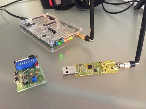
The SDRplay and HackRF One.

Sniffing ANT-FS with an RTL-SDR and MMDS Downconverter in Pothos

ANT-FS is a wireless file transfer protocol that is designed specifically for transferring files wireless between two devices. It is designed for ultra low power devices and typically runs on devices operated by a coin sized battery. It is commonly used in applications like fitness tracker devices, which store data to later be downloaded to a PC.

Over on YouTube user sghctoma has uploaded a video showing a teaser of him receiving and decoding ANT-FS packets with blocks developed for the POTHOS graphical language. As ANT-FS is usually transmitted at 2.4 GHz, he had to use a MMDS downconverter which allowed his RTL-SDR to receive the packets. Sghctoma writes that the video is simply a teaser, and that a live demo with real deivce, and the full code + details will be released during his talk at DEFCON titled “Help, I’ve got ANTs!!!”.

ANT-FS sniffing with RTL-SDR, an MMDS downconverter and Pothosware

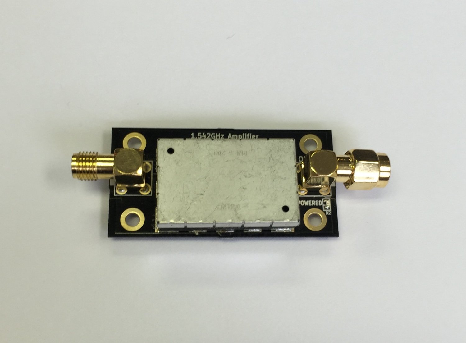
Testing L-Band Inmarsat Reception with Three LNA4ALL’s + Two Filters

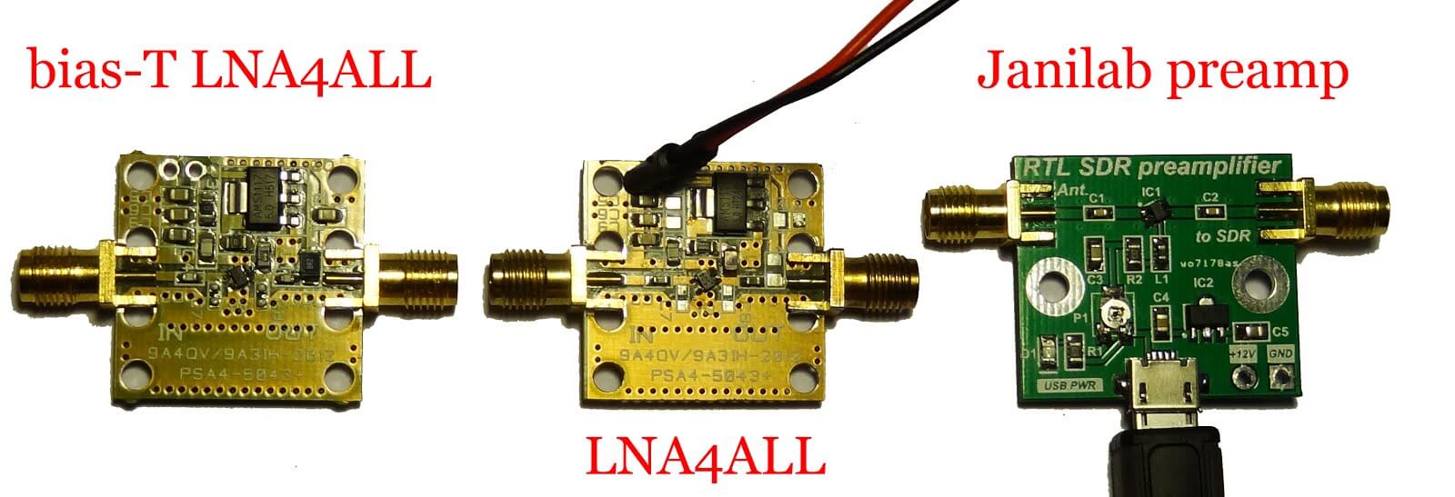
Over the last few weeks Adam 9A4QV has been testing L-Band Inmarsat reception with his LNA4ALL low noise amplifiers. In a previous post he tested reception with two LNA4ALL and found that he got an improved SNR ratio over using just one LNA4ALL. In his latest video he tests Inmarsat reception with three LNA4ALL’s and two L-band filters. His results show that the SNR is improved over using two LNA4ALL’s, and can almost match the results obtained by a commercial L-band front end which he also demonstrated in a previous video.

3x LNA4ALL on L-band + 2 Filters

Building a Quad RTL-SDR Receiver for Radio Astronomy

Amateur radio astronomer Peter W East has recently uploaded a new document to his website. The document details how he built a quad RTL-SDR based receiver for his radio astronomy experiments in interferometry and wide-band pulsar detection (pdf – NOTE: Link Removed. Please see his website for a direct link to the pdf “Quad RTL Receiver for Pulsar Detection”. High traffic from this post and elsewhere has made the document go offline several times). Interferometry is a technique which uses multiple smaller radio dishes spaced some distance apart to essentially get the same resolution a much larger dish. Pulsars are rapidly rotating neutron stars which emit radio waves, and the strongest ones can be observed by amateur radio telescopes and a receiver like the RTL-SDR.

The Quad receiver has four RTL-SDR’s all driven by a single TCXO, mounted inside an aluminum case with fans for air cooling. He also uses a 74HC04 hex inverter to act as a buffer for the 0.5 PPM TCXO that he uses. This ensures that the TCXO signal is strong enough to drive all four RTL-SDRs.

The Quad RTL-SDR with air cooling.

Whilst all the clocks are all synced to a single master clock, synchronisation between the RTL-SDR’s is still difficult to achieve because of jitter introduced by the operating system. To solve this he introduces a noise source and a switch. By switching the noise source on and off, correlation of the signal data can be achieved in post processing.

Noise Source and Switch Calibration Unit.
How correlation with the pulsed noise source works.

In the document Peter shows in detail how the system is constructed, and how it all works, as well as showing some interferometry results. The system uses custom software that he developed and this is all explained in the document as well.

Using the SUP-2400 Downconverter with an LNA and RTL-SDR to Receive 2.4 GHz Video

Earlier in June YouTube user T3CHNOTURK posted a video demonstrating him receiving signals above the maximum 1.7 GHz range of the RTL-SDR by using a modified SUP-2400 downconverter. Back in April it was discovered by KD0CQ that a $5 DirecTV SUP-2400 circuit could be modified and turned into a downconverter for use with the RTL-SDR.

Now T3CHNOTURK has uploaded a new video showing more demonstrations of the RTL-SDR + SUP-2400 combo in action. This time he adds a PGA-103 based LNA to boost the signal strength, which gives him better effective range. In the video he shows reception of a wireless keyboard once again, and then goes on to show him receiving 2.4 GHz analog PAL video using the RTL-SDR program TVSharp. The picture is not particularly clear, but it is a decent demonstration.

RTLSDR, TVsharp 2.4 Ghz video receiver moded SUP-2400 & pga-103 LNA

Remote Spectrum Monitoring Drone with OpenWebRX, Raspberry Pi and an RTL-SDR

Recently Zoltan of rfsparkling.com wrote in to us to show us how he combined efforts with András (programmer of the OpenWebRX software) to create a proof of concept remote spectrum monitoring drone. The drone uses an RTL-SDR connected to a Raspberry Pi, and the Raspberry Pi runs an OpenWebRX server which broadcasts the radio data via 4G mobile internet. The full connection flow chart goes as follows:

[Drone] Antenna –> RTL-SDR –> RPi 2 –> OpenWebRX Server –> 4G mobile net –> … Internet … [Notebook] –> 4G mobile net –> Browser with OpenWebRX client

Zoltan writes that some possible applications include emergency communications, ham radio, 3D spectrum mapping, etc. In the future he also hopes to add TX capabilities, so that the drone can also work a a makeshift transceiver tower. The biggest limitation that Zoltan noted is the flight time of only about 10 minutes. However, a solution he suggests for future experiments is using wire powered drones.

In previous posts we showed Hak5’s remote RTL-SDR ADS-B drone. Their results were not particularly great, however Zoltan and András’ results seem to be much better.

The video below shows an example of Zoltan and András’ drone experiments.

Remote Spectrum Analyzer Drone With OpenWebRX using RTL-SDR and Raspberry Pi

Reverse Engineering a Commercial Inmarsat Front-End to use with the RTL-SDR

Over on his YouTube channel Adam 9A4QV has uploaded a video showing a commercial Inmarsat front end which he reverse engineered to use with his RTL-SDR. The front end is a duplexor, which allows both receive and transmit to occur on the same channel, but to use with the RTL-SDR Adam only uses the receive part. Inside the front end is a large cavity filter, ceramic filter, and about 60 dB of total L-band gain from MMIC amplifiers.

In the second video Adam hooks up the Inmarsat front end to his RTL-SDR and home made patch antenna. The results show that the signals are very strong when using the commercial front end. In a previous post we showed Adam’s results with two LNA4ALL amplifiers. The commercial front end seems to give much stronger signals, but the results with one or two LNA4ALL are adequate enough for decoding.

Inmarsat frontend reverse engineering

Inmarsat frontend test

RTL-SDR Stock Antenna Teardown and VNA Measurements

Over on his YouTube channel oh2ftg has uploaded two new RTL-SDR related videos. In the first video he does a tear down on the stock standard antennas that are supplied with most cheap RTL-SDR units. He finds that most are just a simple design, with the center conductor of the coax soldered to the whip, and the shield pinched between a metal plate and the base.

In his second video he measures the stock antennas on a Vector Network Analyzer (VNA). He places the antennas on a reasonably sized ground plane and finds that the antennas are as expected and pretuned to the DVB-T TV band at around 500 – 600 MHz.

Generally the included antennas are okay for receiving strong signals but we recommend getting yourself an outdoor discone antenna, or building a planar disk (pdf) for more serious scanning.

A look inside five rtl stock antennas

RTL-SDR stock antennas measured on a VNA!