A Tutorial on Receiving WSPR with an RTL-SDR V3
Over on YouTube user Veryokay has uploaded a video that shows how he uses the HF direct sampling mode on one of our V3 RTL-SDR’s to receive WSPR signals. WSPR (pronounced “Whisper”) is short for Weak Signal Propagation Reporting, and is a HF ham mode typically run on very low power levels such as 1W. The data from WSPR reception can be used to determine how good or bad HF propagation is currently around the world as each WSPR message contains the callsign, 6-digit locator and the transmit power level used.
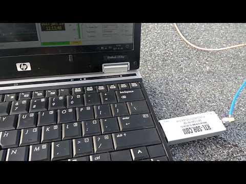
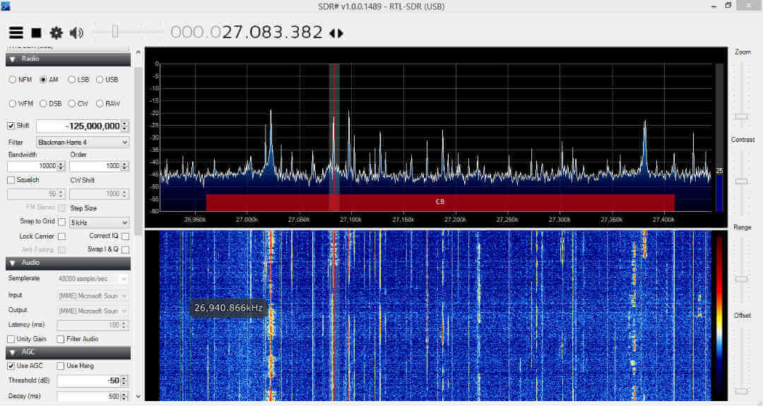
For the antenna Veryokay uses a simple random wire antenna directly connected to the SMA port of the V3 up on top of the roof of his apartment building. This gets him reception good enough to receive many WSPR signals. Then together with SDR#, VB Cable and the WSPR-X decoder software, signals can be received and decoded.
He has also uploaded a document detailing the instructions in text and image form at bit.ly/wspr-rtlsdr.