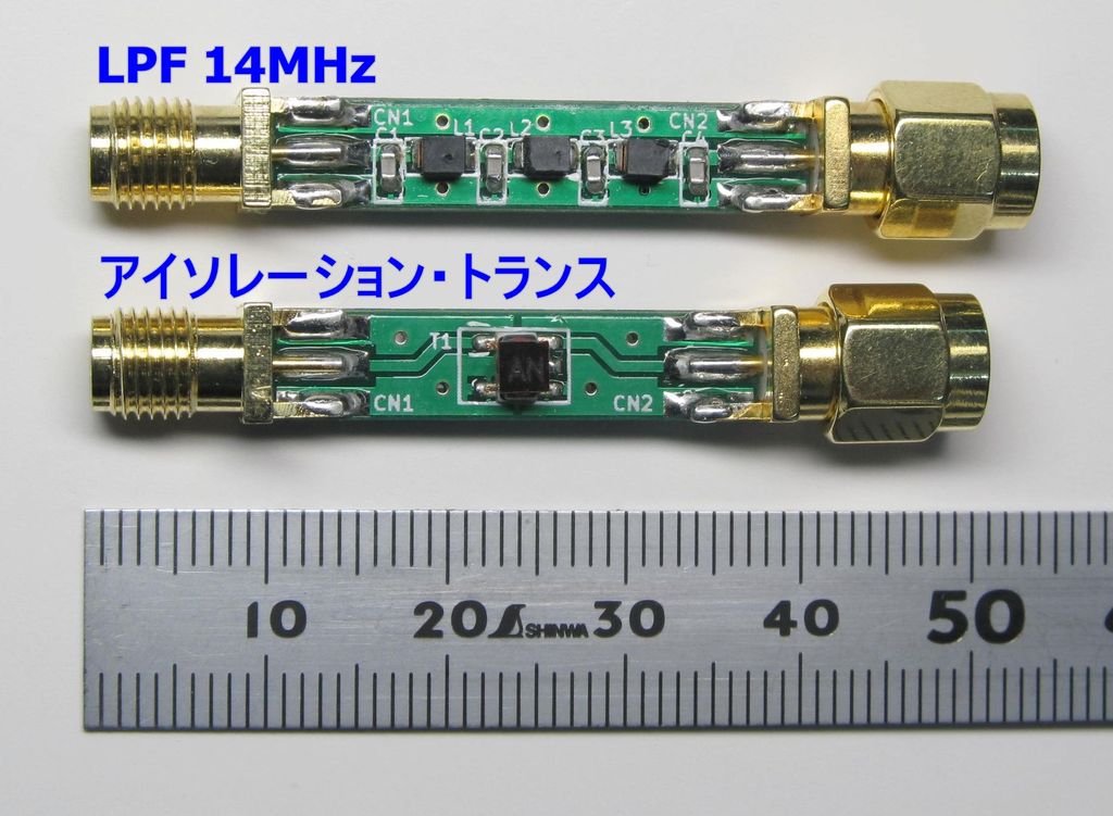
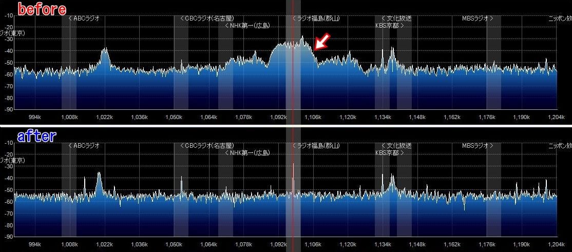
Over on his blog (in Japanese) Nobu has been working on prototyping a 14 MHz low pass filter (LPF) product for direct sampling modified RTL-SDR dongles (in Japanese, use Google Translate). Direct sampling mode is a hardware modification that allows the tuner chip in RTL-SDR dongles to be bypassed, allowing reception of signals between 0 – 14 MHz. However, after performing this mod there is no filtering and images from higher frequencies such as broadcast FM can be problematic. To fix these problems a low pass filter is required.
Another product Nobu is working on is an isolation transformer (aka Galvanic Isolator) which can be used together with an upconverter to help reduce noise generated from common ground sources such as the PC. The isolation transformer is inserted between an upconverter and antenna.
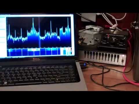
Over on YouTube user kugellagers has uploaded several videos showing how he used two vertical antennas together with an RTL-SDR and ham-it-up upconverter to demonstrate the effect of using a Quantum Phaser to null out strong interfering signals that can cause trouble when DXing.
A Quantum Phaser is a device that combines signals from two antennas in order to create a steerable null. Essentially this means that a strong nearby station coming from one direction that is overlapping a weak remote station coming from another direction can be heavily attenuated, allowing the weak station to come through.
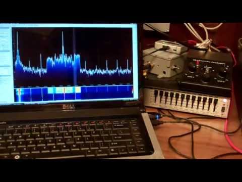
In his videos kugellagers demonstrates the Quantum Phasers nulling effect with splatter from an AM station, an overlapping IBOC hash signal (AM HD Radio) and Non-Directional Beacons (NDBs).
Phasing Out Splatter From a 50 kW Local On Adjacent Channel
Phasing Out IBOC Hash From A Strong Local On Adjacent Channel
Phasing out LF/NDBs With Closely Spaced Vertical Antennas
Programmer Andres has recently been working on creating a toolset for receiving AX.25 packets (FSK 9600) from satellites with an RTL-SDR or other software defined radio. The AX.25 protocol is commonly used for APRS packet radio or telemetry in amateur radio satellites. Andres’ programs focus on using a true UNIX philosophy of piping data between different programs. The toolset consists of doppler correction and demodulation tools and the piping philosophy is demonstrated in the following example:
rtl_sdr | doppler | demod | multimon-ng
Andres writes…
rtl_sdr receives raw IQ data from satellites which is then piped to “doppler” which corrects doppler offset. Zero centered baseband signal is piped to “demod” which outputs demodulated audio suitable for multimon-ng to do actual AX.25 packet decoding.
Such pipeline is intended for resource constrained embedded platforms like RaspberryPi or BeagleBoneBlack where running full blown SDR software would be too much.
The doppler corrector tool works by using the same libraries for calculating satellite positions as those used in Gpredict and the demod tool uses the liquid-dsp library to demodulate the IQ stream.
More information about Andres’ project can be found in these three blog posts that he has written.
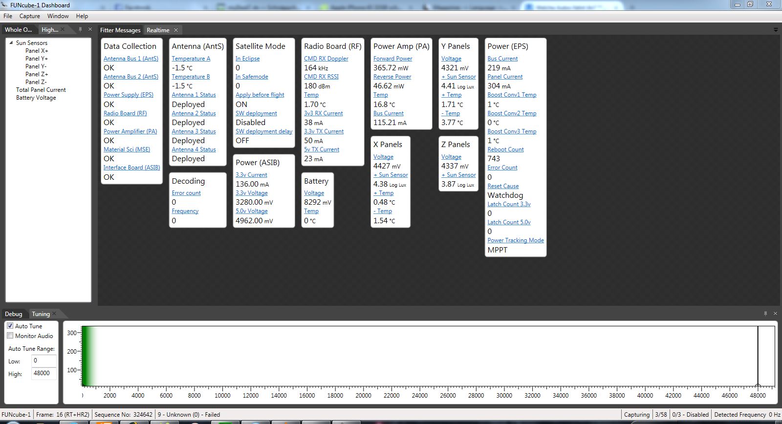
Over on the Hamspirit.de blog author Jan as written a post explaining how to receive the FUNcube satellite with an RTL-SDR dongle (note in German, use Google translate). The FUNcube is a CubeSat (a low cost miniature 10 cm cube sized satellite) which is intended mainly for educating young people about radio, space, physics and electronics, but has also piqued the interest of amateur radio hobbyists.
Jan first writes how the Funcube Dongle was originally invented as a low cost means of receiving the FUNcube satellite, but now there are the even lower cost RTL-SDR dongles. Jan’s post then goes over how to receive the FUNcube at a frequency of 145.935 MHz using software such as SDR-Radio or SDR# and how to decode the telemetry data using the FUNcube dashboard. He also explains a bit about the FUNcubes operating modes which change the satellites transmission strength depending whether or not its solar panels are in sunlight or not.
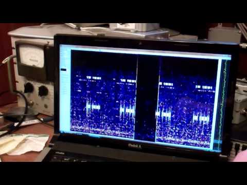
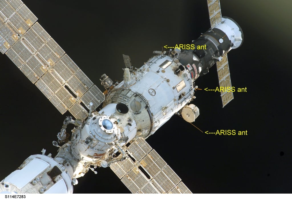
Happysat, a reader of RTL-SDR.com has written in to remind us that the International Space Station (ISS) is currently transmitting slow scan television (SSTV) images out of respect of the 80th birthday of Russian cosmonaut and first man to go to space Yuri Gagarin. The images will be transmitted continuously until 24 February 21.30 UTC.
SSTV is a type of radio protocol that is used to transmit low resolution images over radio. A RTL-SDR dongle and satellite antenna (QFH, turnstile, even terrestrial antennas like random wire antennas and monopoles have been reported to work) can be used to receive and decode these images. Happysat writes that it is expected that the ISS will continuously transmit 12 images at a frequency of 145.800 MHz FM using the SSTV mode PD180, with 3 minute off periods between each image.
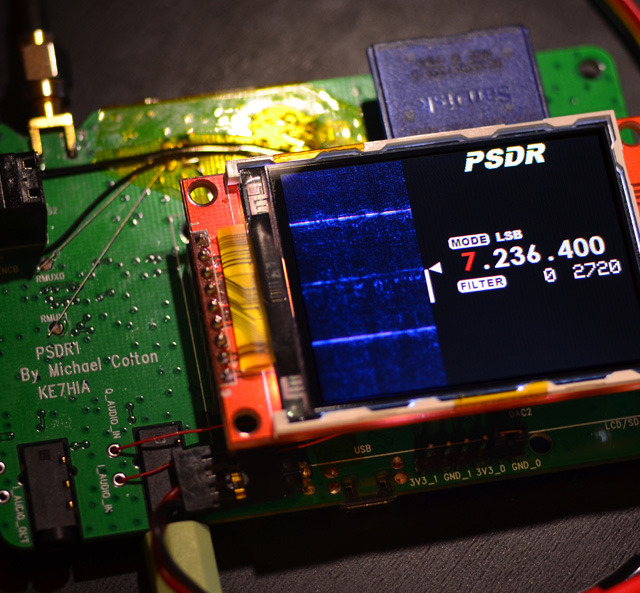
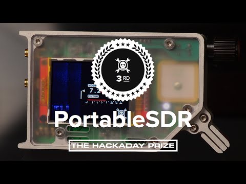
Back in November, 2014 we posted about the PortableSDR, a 0 – 35 MHz portable software defined radio transceiver that was the third place winner in the Hackaday Prize competition. The PortableSDR project is gaining traction and now has a Kickstarter campaign. They write:
The Portable Software Defined Radio, or PSDR, is an Open Source, Fully stand-alone HF/Shortwave Software Defined Transceiver. It includes a Vector Network Analyzer and Antenna Analyzer as well as GPS. It’s built for rugged portable use. It is designed to be a flexible platform for development, a learning aid, and and a useful instrument for electronics enthusiasts.
Features:
Coverage from 0 to 35MHz
Waterfall display that lets you see radio signals
Receives AM, USB (Upper Side Band), LSB (Lower Side Band), and Morse code (CW)
Modulates USB and LSB signals
Variable bandpass filter
The campaign hopes to raise $60,000 USD to aid in the development of the hardware and software and with the manufacturing process. The kickstarter is offering kits at various stages of completion from $250 to $475 and a fully assembled kit at $499. They note that the current PSDR2 that you will receive from the Kickstarter is still a development version, not the final product. The PSDR2 is missing some key features that will be in the final version like filters and output amplifiers.
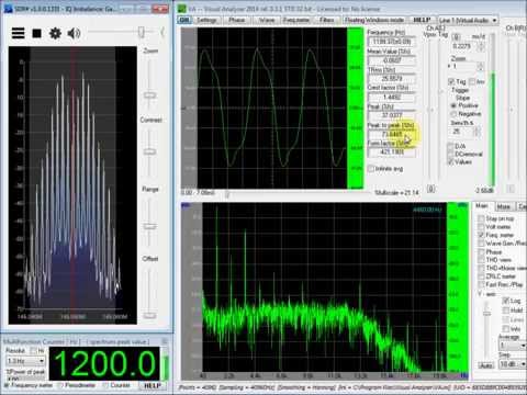
Over on YouTube user KP4MD has uploaded a video showing how she uses an RTL-SDR together with SDR#, a program called Visual Analyzer and an AEA PK-232 Terminal Node Controller to measure the frequency deviation of a Yaesu FT-8800R Transceiver. She writes:
The SDR# receiver is tuned to 145.050 MHz and the bandwidth set to 20 kHz.
The deviation level of the 1200 Hz tone is increased until a null appeared on the carrier frequency.
This is called a Bessel Zero and occurs at various predicted modulation indices (2.4, 5.52, 8.66, etc).
The Modulation Index is defined as the peak frequency deviation divided by the modulation frequency.
This Bessel Zero occurred at a modulation index of 2.4 corresponding to a frequency deviation of ±2.88 kHz (2.4 x 1.2 kHz).
The oscilloscope indicates that a peak to peak amplitude of 54.3% corresponds to ±2.88 kHz deviation.
The 1200 Hz tone modulation is increased to yield a peak to peak amplitude of 66%.
This corresponds to the desired ±3.5 kHz frequency deviation.
Frequency Deviation Measurement with an RTL-SDR Dongle
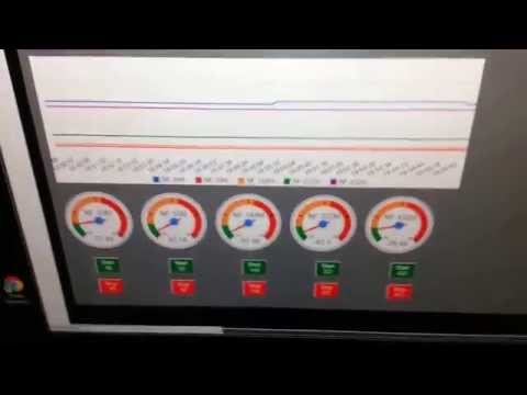
Tim’s system uses a powerful Odroid XU3 which is a Linux based mini embedded computer that sells for $179 USD. The Odroid XU3 has dual quad core ARM CPUs which is enough power to run rtl_power with 5 RTL-SDR dongles simultaneously. Rtl_power is an RTL-SDR tool which allows you to scan and record the power levels in the frequency spectrum. By using 5 dongles he is able to scan the 49 MHz, 50 MHz, 144 MHz, 222 MHz and 432 MHz bands simultaneously.
The idea behind this project is to be able to MAP real-world Geo-tagged noise floor readings. This can be used for the primary purpose I intended for this application (mapping of problematic sources of RF Noise related to power lines in the area so that I can approach the local power company to resolve them) or any other sort of RF signal MAPPING. Such as cellphone/cellsite coverage or FM broadcast coverage (and dead spots) among other things.
RTL dongles are CHEAP, and reliable, although not 100% stable (they drift a bit for the first 5 minutes of warm up) they can be used to measure changes in the RF Noise Floor (once warmed up). While they don’t really seem to be able to be calibrated to anything less than -87db all we’re really looking for are relative changes to the noise floor while driving around a particular location (there is probably some complex math that could applied to these measurements that could be calibrated). So for this project these inexpensive receivers are really just fine.
While rtl_power is scanning, the Odroid uses a GPS receiver to tag the timestamped noise readings with GPS coordinates. Then by driving around with the system and combining the GPS coordinates with the noise floor readings from rtl_power he is able to create a heatmap showing exactly where in his neighbourhood noise levels peak, indicating a power line RF noise problem to be fixed by the power company.
Some more information about the hardware build of his system can be found on a previous post.
Powerline Noise Heat Mapped with RTL-SDRs and GPS LoggingThe insides of the driveby system
Tim also has uploaded a video to YouTube showing his system running a stationary test demonstrating the hardware and some of his custom software before everything was boxed up.