Back in early November we posted about the upcoming XTRX SDR, which is a small form factor 2 x 2 MIMO TX and RX capable SDR that is designed to fit into laptop Mini PCIE card slots. It is based on the LimeSDR RF chips, and has a tuning range of 10 MHz - 3.7 GHz, with a sample rate of up to 120 MSPS. It is also has some interesting additional features such as a built in GPSDO and an onboard FPGA which can be used to accelerate DSP tasks as well. The Mini PCIE interface was chosen for it's low latency transfer rates.
The card is designed for use cases such as creating LTE cellular networks, creating software defined 2G/3G/4G modems and using on board drones and in embedded systems. It can also be used for standard wideband monitoring and of course any other SDR applications compatible with Lime chips.
Today the crowdfunding campaign for the XTRX has begun. The early bird pricing is $179 USD (with 71 left at the time of this post - going down fast!), and the regular price is $199 USD. There are accessories available as well such as antenna and cable kits, a PCIe x2 adapter and a USB 3.0 adapter kit with enclosure. The XTRX team are hoping to raise 90k USD, with already 8k USD having been raised at the time of this post.
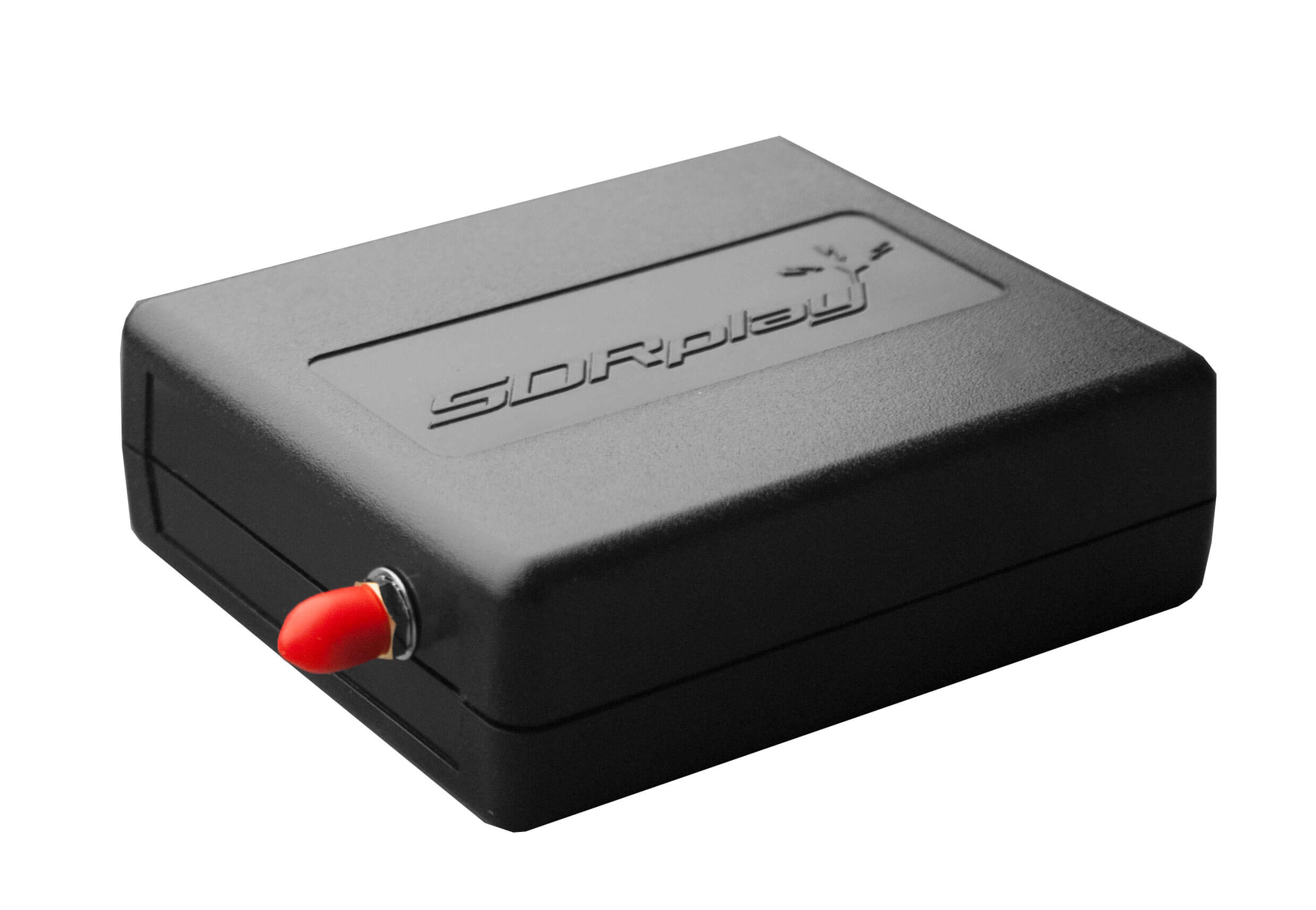
SDRplay Limited has today announced the launch of a new Software Defined Radio product – the RSP1A.
The SDR-play RSP1A is a major upgrade to the popular RSP1 and is a powerful wideband full featured 14-bit SDR which covers the RF spectrum from 1 kHz to 2 GHz.
Due to its exceptional combination of performance and price, the RSP1 has proved to be a very popular choice as an “entry level” SDR receiver. Since launching the RSP1, we have learned a great deal about what people are looking for in SDR receivers, and where possible, we have incorporated these improvements and new features into the RSP1A.
The RSP1A therefore delivers a significant number of additional features which result in benefits to amateur radio enthusiasts as well as significant benefits for the scientific, educational and industrial SDR community.
Here are the main additional features of the RSP1A compared to the original RSP1:
ADC resolution increased to 14-bit native for sample rates below 6 MHz, increasing to 16 bits with decimation.
Enhanced RF pre-selection (greater filter selectivity plus 4 additional sub-bands compared to the original RSP1) for reduced levels of spurious responses
Improved LNA architecture with variable gain. The RSP1 had just a single gain step.
Improved intermodulation performance
Performance extended to cover 1kHz to 2GHz with a single antenna port.
Bias-T facility
Improved frequency stability incorporating a 0.5ppm TCXO (software trimmable to 0.01ppm)
Selectable broadcast AM/FM/DAB notch filters
RF shielding within the robust plastic casing
When used together SDRplay’s own SDRuno software, the RSP1A becomes a high performance SDR platform. The benefits of using the RSP1A with SDRuno include:
Highly integrated native support for the RSP1A
Calibrated RF Power Meter with more than 100 dB of usable range
Calibrated S-Meter including support for IARU S-Meter Standard
The ability to save power (dBm) and SNR (dB) measurements over time, to a CSV file for future analysis
The IQ output wav files can be accessed for 3rd party applications
SDRplay has also worked with developers of the popular HDSDR, SDR-Console and Cubic SDR software packages to ensure compatibility. As with the RSP1, SDRplay provides multiplatform driver and API support which includes Windows, Linux, Mac, Android and Raspberry Pi 3. There is even a downloadable SD card image available for Raspberry Pi3 which includes Cubic SDR.
The RSP1A is expected to retail at approximately £76 (excluding taxes) or $100 (excluding taxes) For more information visit our website on www.sdrplay.com
About SDRplay:
SDRplay limited is a UK company and consists of a small group of engineers with strong connections to the UK Wireless semiconductor industry. SDRplay announced its first product, the RSP1 in August 2014
We've had a RSP1A beta preproduction unit for a few weeks now and will be releasing a full review comparing it against the RSP1 in a day or so. For a quick review conclusion we note that we've noticed that the filters are significantly more effective on the RSP1A compared to the RSP1, and the inclusion of the MW/FM and DAB notch filters help a lot in certain situations. The increased ADC resolution is due to decimation on board the MSi2500 chip and is noticeable in some situations, but does not seem to cause a huge improvement. Overall compared to the RSP1 some overloading problems are still present with strong signals, but intermodulation and imaging is reduced significantly and in some cases the RSP1A even outperforms the RSP2.
Also, Mike Ladd KD2KOG a member of the SDRplay technical support team has uploaded a video announcing and demoing the RSP1A.
The much anticipated Airspy HF+ has just been released for sale. The cost is $199 USD plus shipping from the manufacturer iTead in China which costs about $6 for a registered air mail parcel or $19 for DHL express delivery to the USA. There was a coupon available via this tweet, but it ran out within hours.
Note that we believe that these are preorders, with shipping expected to commence in early December.
If you didn't know already the Airspy HF+ is a HF/VHF RX only SDR which has extremely high dynamic range and excellent sensitivity. The high dynamic range means that the SDR is unlikely to ever overload on strong signals meaning that no external filtering which can reduce SNR/sensitivity is required. The minimum discernible signal (MDS) measurements are also excellent meaning that sensitivity to weak signals is excellent too. With high dynamic range, great sensitivity and low cost combined, this SDR blows most of the current offerings out of the water by being able to 'just work' without the need to fiddle around with gain sliders, filters or attenuation.
Airspy HF+: Why Linearity Matters
The only disadvantage to similar offerings like the Airspy R2/Mini or SDRplay is the reduced frequency range and bandwidth specs. On the HF+ the frequency range tops out at 260 MHz and the bandwidth at 680 kHz. The Airspy R2/mini/SDRplay units have frequency ranges that go up to 1.8 - 2 GHz, and have bandwidths of up to 10 MHz. But this is an SDR designed for DXing or pulling in those weak signals, so wideband operation is not a major concern for that application.
We have a review of a prototype version of the Airspy HF+ that we received earlier in the year available here. It's one of the most impressive low cost SDRs that we've seen to date. (We consider sub $300 USD as low cost, and $20 RTL-SDRs as ultra-low cost). You can also freely test some publicly available Airspy HF+ units that were provided to reviewers and developers over the internet.
Technical specifications
HF coverage between 9 kHz .. 31 MHz
VHF coverage between 60 .. 260 MHz
-140.0 dBm (0.02 µV / 50 ohms at 15MHz) MDS Typ. at 500Hz bandwidth in HF
-141.5 dBm MDS Typ. at 500 Hz bandwidth in FM Broadcast Band (60 – 108 MHz)
-142.5 dBm MDS Typ. at 500 Hz bandwidth in VHF Aviation Band (118 – 136 MHz)
-140.5 dBm MDS Typ. at 500 Hz bandwidth in VHF Commercial Band (136 – 174 MHz)
-140.0 dBm MDS Typ. at 500 Hz bandwidth in the upper VHF Band (> 174 MHz)
+15 dBm IIP3 on HF at maximum gain
+13 dBm IIP3 on VHF at maximum gain
110 dB blocking dynamic range (BDR) in HF
95 dB blocking dynamic range (BDR) in VHF
150+ dB combined selectivity (hardware + software)
120 dB Image Rejection (software)
Up to 660 kHz alias and image free output for 768 ksps IQ
18 bit Embedded Digital Down Converter (DDC)
22 bit! Resolution at 3 kHz channel using State of the Art DDC (SDR# and SDR-Console)
Over on the crowd funding site crowdsupply.com there have recently been several updates on the Fairwaves XTRX SDR. The XTRX is an upcoming TX/RX capable SDR in a tiny Mini PCIe form factor. Mini PCIe is the expansion slot system used on some laptops. The SDR itself will be 2 x 2 MIMO, with a tuning range of 10 MHz - 3.7 GHz (down to 100 kHz with some degradation), and have a sample rate of up to 120 MSPS. It uses the LimeSDR RF chipset which provides most of the hardware required.
The XTRX is not yet for sale, and is planned for a crowdfunding run on Crowdsupply 'soon'. You can subscribe to future updates on their page. No word yet on pricing, but according to one of the developers comments on Reddit the price will be somewhere between the LimeSDR ($299 USD) and LimeSDR Mini ($139 USD). Eventually in the future if they can tap into a mass market they hope to get the price down to $50 USD.
Features & Specifications
RF Chipset: Lime Microsystems LMS7002M FPRF
FPGA Chipset: Xilinx Artix 7 35T
Channels: 2 × 2 MIMO
Tuning Range: 30 MHz - 3.8 GHz
Rx/Tx Range:
10 MHz - 3.7 GHz
100 kHz - 3.8 GHz with signal level degradation
PCIe Bandwidth:
PCIe x2 Gen 2.0: 8 Gbit/s
PCIe x1 Gen 2.0: 4 Gbit/s
PCIe x1 Gen 1.0: 2 Gbit/s
Sample Rate: ~0.2 MSPS to 120 MSPS
Reference clock:
Frequency: 26 MHz
Stability: <10 ppb stability after GPS/GNSS lock, 500 ppb at start up
Form Factor: full-size miniPCIe (30 × 51 mm)
Bus Latency: <10 µs, stable over time
Synchronization: synchronize multiple XTRX boards for massive MIMO
This is just an announcement post to say that the RTL-SDR Blog V3 is now back in stock at Amazon USA and should be ready for shipping from there soon.
These include our bundle that comes with the new multipurpose dipole antenna kit for $25.95 USD. Please go to rtl-sdr.com/DIPOLE for further information about the new dipole kit.
Over on our store we now sell our dongles with a receive only dipole antenna kit that replaces the older magnetic whip style antennas from the previous kit. This was done for a few reasons
We believe that the dipole kit is much more versatile and will enable beginners to get better reception straight away
Magnets of any type are difficult to ship as they are not allowed by many airmail carriers.
While the magnetic whip still works perfectly fine, the dipole kit should make it easier to get the antenna outside or in a better position away from noisy computers/electronics, and it also allows for a simple v-dipole configuration for satellite reception.
The units are currently in stock at our Chinese warehouse either bundled with an RTL-SDR or as an individual antenna set.
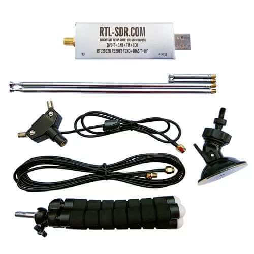
This post is a guide on how to use the dipole antenna set in various configurations. First we'll show and explain about what's included in the set:
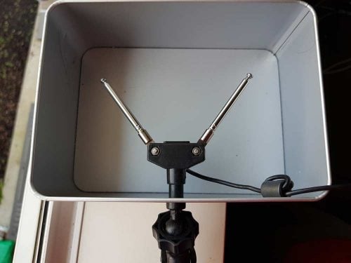
1x dipole antenna base with 60cm RG174 cable and SMA Male connector. This is the dipole base where the telescopic antennas connect to. The short run of RG174 is decoupled from the base elements with a ferrite choke. This helps to prevent the feed line from interfering with the dipole radiation pattern. The dipole has a 1/4 inch female screw on the bottom, which allows you to use standard camera mount products for mounting.
1x 3 meter RG174 coax cable extension. This coax cable extension allows you to mount the antennas in a place that gets better reception. E.g. outside on a window, or higher up.
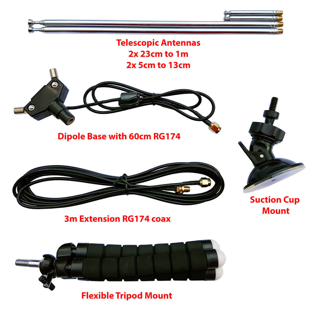
2x 23cm to 1 m telescopic antennas. The telescopic dipoles are detachable from the dipole base via a M5 thread which allows for greater portability and the ability to swap them out. These long telescopic antennas cover VHF to UHF.
2x 5cm to 13cm telescopic antennas. These smaller antennas cover UHF to 1090 MHz ADS-B, and even still work decently up to L-band 1.5 GHz frequencies.
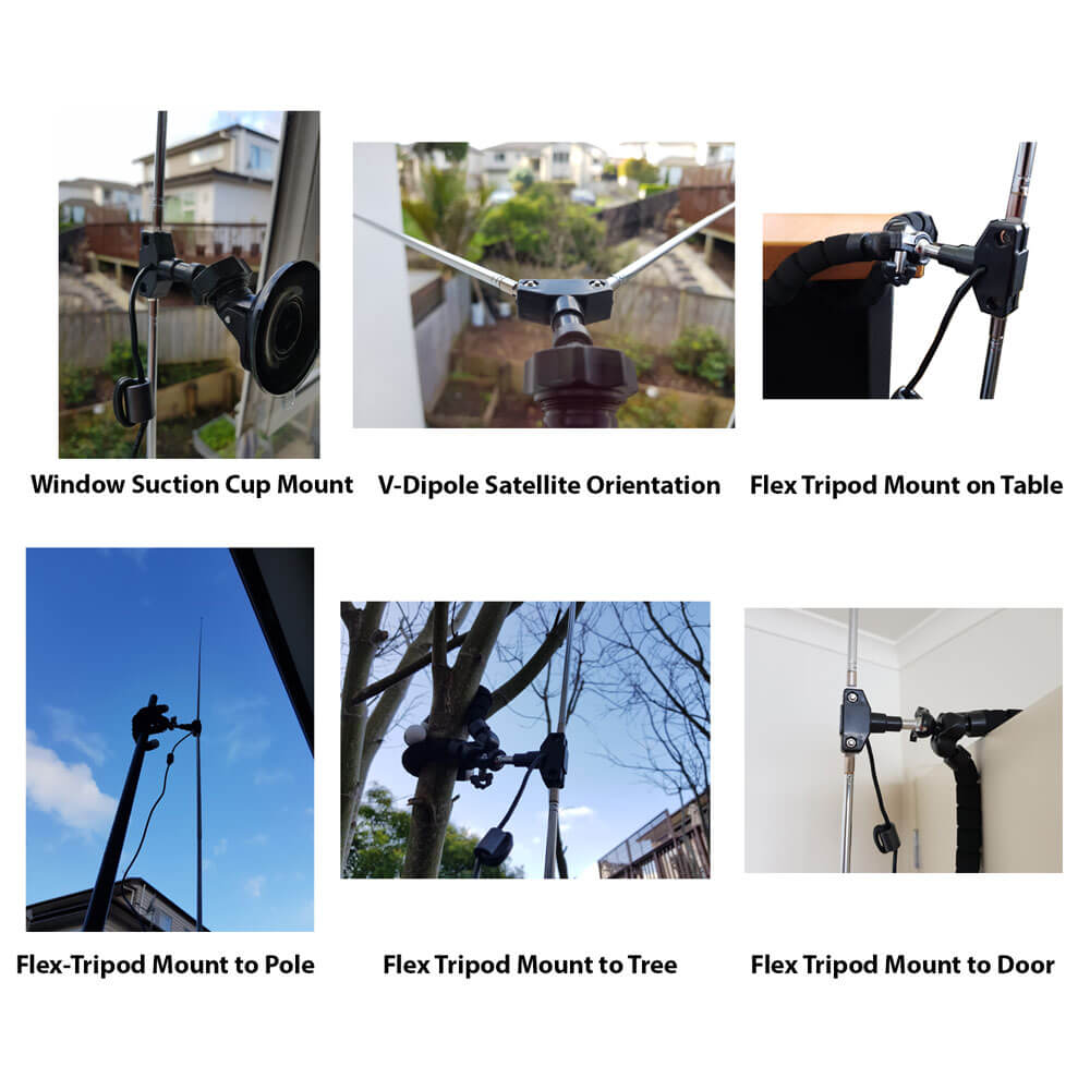
1x flexible tripod mount with 1/4" male screw. This piece allows you to mount the dipole on a variety of different locations. E.g. a pole, tree branch, desk, door, window sill. The legs of the tripod are bendy and rubberized so can wrap securely around many objects.
1x suction cup mount with 1/4" male screw. With this mount you can mount the dipole on the outside of a window, on a wall, car roof/window, or on any other smooth surface. To use first clean the surface with window cleaner or isopropyl alcohol. Then place the suction cup on the cleaned surface and close the lever to activate the suction.
What's included in the new Dipole kit
Dipole Orientation
Signals are normally transmitted with either horizontal, vertical or right hand/left hand circular polarization (RHCP/LHCP). This is essentially the 'orientation' of a signal, and an antenna with the same polarization should be used too for best performance. A dipole can be used in either vertical or horizontal polarization, just by orienting it either vertically or horizontally.
If you mismatch vertical and horizontal polarization or RHCP and LHCP you'll get an instant 20dB loss. If you mismatch vertical/RHCP, vertical/LHCP, horizontal/RHCP, horizontal/LHCP you'll only get a 3dB loss.
For vertical polarization, in theory it does not matter which way around you orient the antenna as long as it's vertical. However in practice, you may get slightly better results by having the element connected to the center coax conductor pointing UP. You can confirm which element is connected to the center conductor by temporarily removing the black lid on the dipole base (it can be easily pried off with a nail or flat head screwdriver).
There are also ways to optimize the radiation pattern with dipoles. For example for LEO VHF satellites you can use a V-dipole configuration. You can also make a somewhat directional antenna by using a bent dipole configuration. Some more examples of dipole configurations can be found on KK4OBI's page on bent dipoles.
Terrestrial Signal Reception
Most signals broadcast terrestrially (on Earth) are vertically polarized.
To use the dipole for vertically polarized signals, all that you need to do is orient the elements vertically (up and down).
In theory there is no up and down for the dipole when used in the vertical orientation. However in practice you may find slightly better performance when the 'active' element points up. The active element is the one connected to the center conductor. You can check which element is connected to the center conductor by removing the top cap on the dipole base. This will let you look inside at the connections.
Satellite Reception
The dipole can be used in a V-Dipole configuration for polar orbiting satellite reception. See Adam 9A4QV's post where he wrote about how he discovered that it was possible to use dipoles in this configuration for excellent satellite reception. The idea is to use the dipole in horizontal polarization. This gives 3dB loss on the RHCP satellite signals, but also nicely gives 20dB loss on terrestrial signals which could be overloading your RTL-SDR.
For 137 MHz satellites like NOAA and Meteor M2 extend the larger antenna elements out to about 53.4 cm each (about 2.5 sections). Angle the dipole so it is horizontal and in a 'Vee' shape, at about 120 degrees. Place the dipole in the North-Source direction.
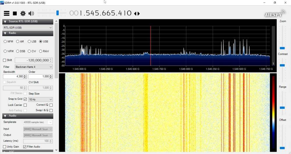
With an appropriate L-band LNA like the Outernet LNA the dipole can also somewhat work to receive L-band satellites. Using the smallest antenna collapsed, use a V-dipole configuration and point it towards the L-band satellite. Ideally use a reflector too. In the image below we used a simple cookie tin as a reflector. A hole was drilled into the center and the mount used to clamp in the antenna. This together with the Outernet LNA was enough to receive AERO and STD-C.
Choosing the Antenna Element Length
Like with the whip you can use an online calculator to calculate the optimal length for your frequency of interest. We recommend this dipole calculator. The exact length does not matter too much, but try to get the lengths as close to what the calculator says as you can. With the dipole you want both elements to be the same length.
In reality extending the antenna to almost any random length will work just fine for most strong signals. But if you're really trying to optimize those weak signals you'll want to fine tune the lengths.
Basically the longer the antenna, the lower it's resonant frequency. The shorter the antenna, the higher the resonant frequency. You want to be close to the resonant frequency. Remember that there is about 2cm of metal inside the antenna itself which needs to be added on. Below is a cheat sheet for various lengths and frequencies. Note that the length refers to the length of one side of the dipole only (e.g. the length that you need to extend each element out to).
Large Antenna, 5 Sections, 100cm + 2cm is resonant @ ~70 MHz
Large Antenna, 4 Sections, 80cm + 2cm is resonant @ ~87MHz
Large Antenna, 3 Sections, 60cm + 2cm is resonant @ ~115 MHz
Large Antenna, 2 Sections, 42cm + 2cm is resonant @ ~162 MHz
Large Antenna, 1 Section, 23cm + 2cm is resonant @ ~ 285 MHz
Small Antenna, 4 Sections, 14cm + 2cm is resonant @ ~445 MHz
Small Antenna, 3 Sections, 11cm + 2cm is resonant @ ~550 MHz
Small Antenna, 2 Sections, 8cm + 2cm is resonant @ ~720MHz
Small Antenna, 1 Section, 5cm + 2cm is resonant @ ~1030 MHz.
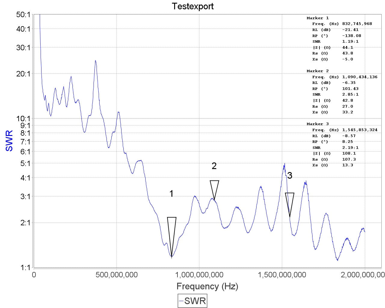
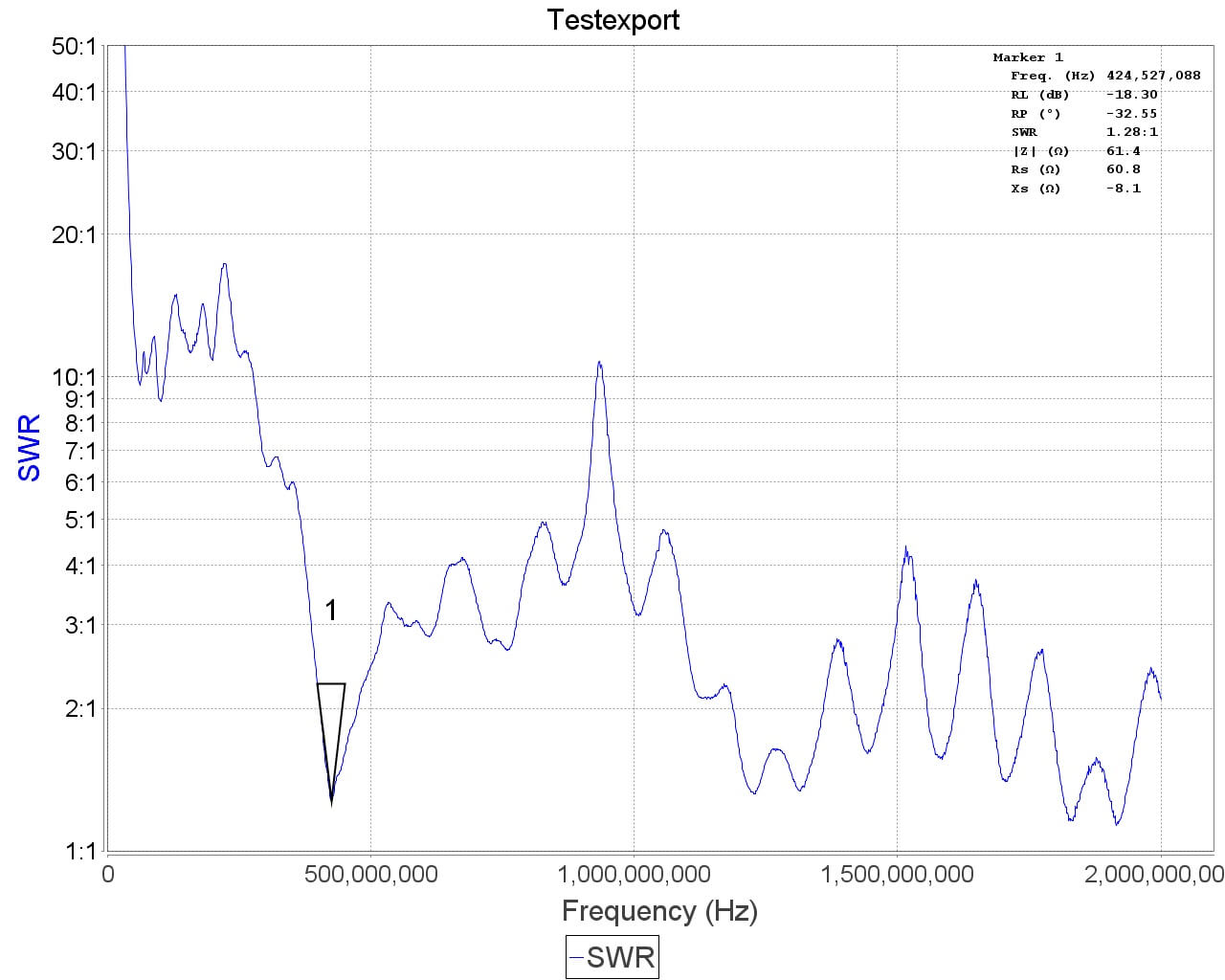
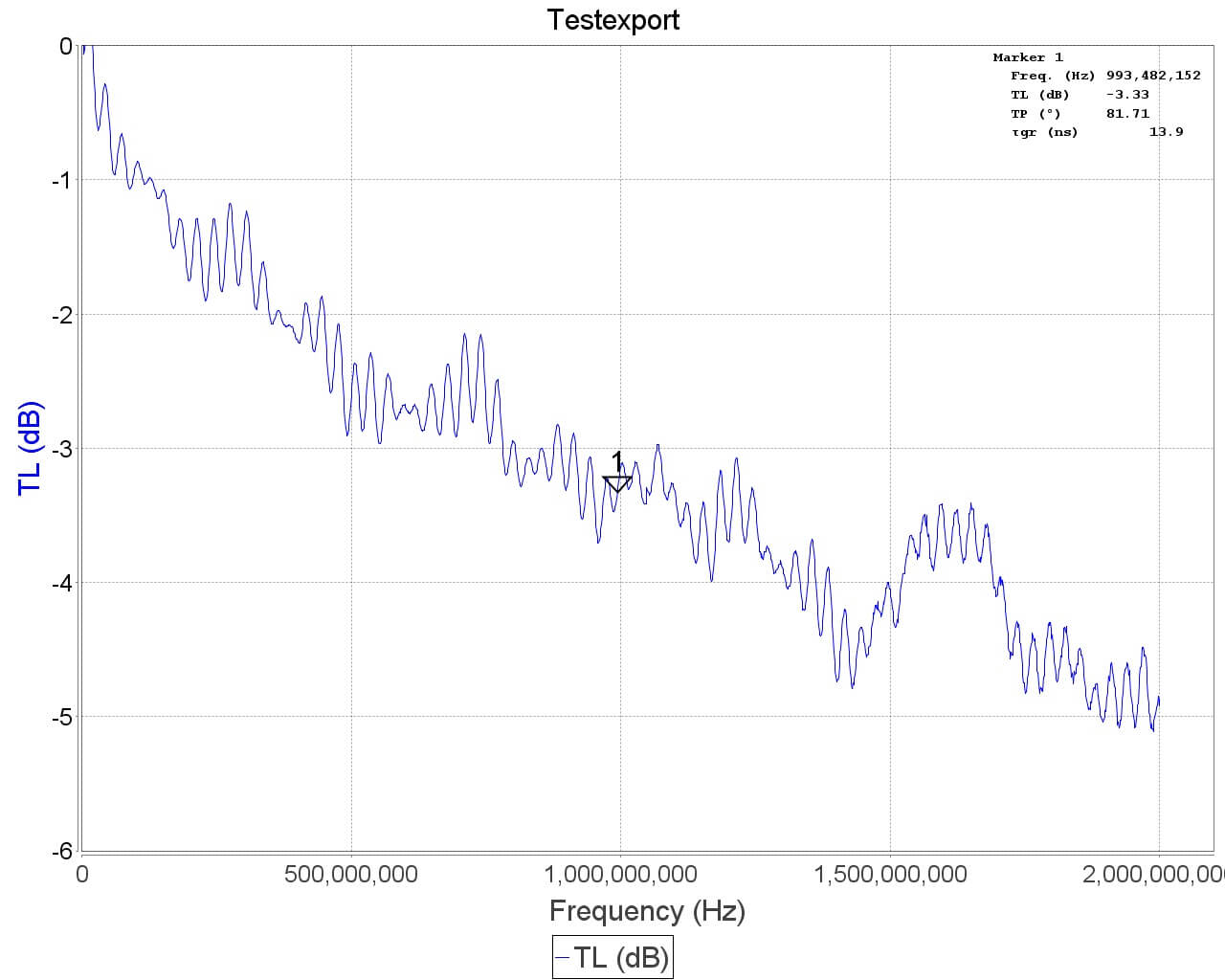
See the SWR plots at the end for a more accurate reading of the resonance points. But in most cases no matter what you extend the length to the SWR should be below 5 at most frequencies which results in 2.5 dB loss or less. More accurate info on VSWR loss graphs can be found in this document from the ARRL "Understanding SWR by Example" (pdf).
Using the Mounts
The suction cup mount allows you to easily place the antenna on a window, or any smooth surface. To use it first clean the surface thoroughly with isopropyl alcohol or glass cleaner. Then apply the suction cup and close the lever to lock it in place. The lever requires some force to push down, and this ensures a strong grip. You can then angle the antenna in the orientation that you need using the ball socket. Once in place close the ring to lock the ball socket in place.
The flexible tripod mount is useful to mounting the dipole to almost everything else. Including tables, doors, poles, trees etc. The legs of the tripod have a flexible metal wire inside and rubber sheath so they can be bent into a position to grip almost anything.
Some examples of how to use the mounts.
Note that the mounts and RG174 extension allow you to more easily use the dipole antennas outside or in a better indoors position (e.g. on a Window). But please note that like our older magnetic whip we do not recommend permanently mounting this antenna outdoors. This antenna is designed to be a portable antenna that you put up and take down at the end of the day - not for permanent outdoor mounting. It is not protected against water, not grounded so cannot handle a lightning strike and could be damaged with dirt and grime build up. For permanent outdoor mounting you could conceivably fill the inside and hinges of the dipole with silicon putty or maybe even hot glue and ground the antenna yourself, but we have not tested this. The stainless steel antennas won't rust, but dirt and grime could gum up the collapsing mechanism.
Tightening the hinge
Once you've got the orientation of the dipoles the way you want, you might want to tighten the hinge so the elements don't move so easily anymore. To do this simply take a small screwdriver and tighten the screw on the hinge.
ESD Bleed Resistor
Note that our older antennas had a 100kOhm ESD bleed resistor between the two elements. This is no longer the case on newer models. The purpose of the resistor was to slowly bleed any ESD buildup to ground.
We decided to improve ESD protection on the dongle instead, so the ESD bleed resistor is not longer required and is now omitted on newer productions.
Sample VSWR Plots
Other Notes
Note that this is NOT an antenna designed for TXing. It is an RX antenna only. So please do not TX with it unless you really know what you are doing as you could damage your TX radio.
Back in early November we posted about the upcoming XTRX SDR, which is a small form factor 2 x 2 MIMO TX and RX capable SDR that is designed to fit into laptop Mini PCIE card slots. It is based on the LimeSDR RF chips, and has a tuning range of 10 MHz - 3.7 GHz, with a sample rate of up to 120 MSPS. It is also has some interesting additional features such as a built in GPSDO and an onboard FPGA which can be used to accelerate DSP tasks as well. The Mini PCIE interface was chosen for it's low latency transfer rates.
The card is designed for use cases such as creating LTE cellular networks, creating software defined 2G/3G/4G modems and using on board drones and in embedded systems. It can also be used for standard wideband monitoring and of course any other SDR applications compatible with Lime chips.
Today the crowdfunding campaign for the XTRX has begun. The early bird pricing is $179 USD (with 71 left at the time of this post - going down fast!), and the regular price is $199 USD. There are accessories available as well such as antenna and cable kits, a PCIe x2 adapter and a USB 3.0 adapter kit with enclosure. The XTRX team are hoping to raise 90k USD, with already 8k USD having been raised at the time of this post.
SDRplay Limited has today announced the launch of a new Software Defined Radio product – the RSP1A.
The SDR-play RSP1A is a major upgrade to the popular RSP1 and is a powerful wideband full featured 14-bit SDR which covers the RF spectrum from 1 kHz to 2 GHz.
Due to its exceptional combination of performance and price, the RSP1 has proved to be a very popular choice as an “entry level” SDR receiver. Since launching the RSP1, we have learned a great deal about what people are looking for in SDR receivers, and where possible, we have incorporated these improvements and new features into the RSP1A.
The RSP1A therefore delivers a significant number of additional features which result in benefits to amateur radio enthusiasts as well as significant benefits for the scientific, educational and industrial SDR community.
Here are the main additional features of the RSP1A compared to the original RSP1:
ADC resolution increased to 14-bit native for sample rates below 6 MHz, increasing to 16 bits with decimation.
Enhanced RF pre-selection (greater filter selectivity plus 4 additional sub-bands compared to the original RSP1) for reduced levels of spurious responses
Improved LNA architecture with variable gain. The RSP1 had just a single gain step.
Improved intermodulation performance
Performance extended to cover 1kHz to 2GHz with a single antenna port.
Bias-T facility
Improved frequency stability incorporating a 0.5ppm TCXO (software trimmable to 0.01ppm)
Selectable broadcast AM/FM/DAB notch filters
RF shielding within the robust plastic casing
When used together SDRplay’s own SDRuno software, the RSP1A becomes a high performance SDR platform. The benefits of using the RSP1A with SDRuno include:
Highly integrated native support for the RSP1A
Calibrated RF Power Meter with more than 100 dB of usable range
Calibrated S-Meter including support for IARU S-Meter Standard
The ability to save power (dBm) and SNR (dB) measurements over time, to a CSV file for future analysis
The IQ output wav files can be accessed for 3rd party applications
SDRplay has also worked with developers of the popular HDSDR, SDR-Console and Cubic SDR software packages to ensure compatibility. As with the RSP1, SDRplay provides multiplatform driver and API support which includes Windows, Linux, Mac, Android and Raspberry Pi 3. There is even a downloadable SD card image available for Raspberry Pi3 which includes Cubic SDR.
The RSP1A is expected to retail at approximately £76 (excluding taxes) or $100 (excluding taxes) For more information visit our website on www.sdrplay.com
About SDRplay:
SDRplay limited is a UK company and consists of a small group of engineers with strong connections to the UK Wireless semiconductor industry. SDRplay announced its first product, the RSP1 in August 2014
We've had a RSP1A beta preproduction unit for a few weeks now and will be releasing a full review comparing it against the RSP1 in a day or so. For a quick review conclusion we note that we've noticed that the filters are significantly more effective on the RSP1A compared to the RSP1, and the inclusion of the MW/FM and DAB notch filters help a lot in certain situations. The increased ADC resolution is due to decimation on board the MSi2500 chip and is noticeable in some situations, but does not seem to cause a huge improvement. Overall compared to the RSP1 some overloading problems are still present with strong signals, but intermodulation and imaging is reduced significantly and in some cases the RSP1A even outperforms the RSP2.
Also, Mike Ladd KD2KOG a member of the SDRplay technical support team has uploaded a video announcing and demoing the RSP1A.
The much anticipated Airspy HF+ has just been released for sale. The cost is $199 USD plus shipping from the manufacturer iTead in China which costs about $6 for a registered air mail parcel or $19 for DHL express delivery to the USA. There was a coupon available via this tweet, but it ran out within hours.
Note that we believe that these are preorders, with shipping expected to commence in early December.
If you didn't know already the Airspy HF+ is a HF/VHF RX only SDR which has extremely high dynamic range and excellent sensitivity. The high dynamic range means that the SDR is unlikely to ever overload on strong signals meaning that no external filtering which can reduce SNR/sensitivity is required. The minimum discernible signal (MDS) measurements are also excellent meaning that sensitivity to weak signals is excellent too. With high dynamic range, great sensitivity and low cost combined, this SDR blows most of the current offerings out of the water by being able to 'just work' without the need to fiddle around with gain sliders, filters or attenuation.
Airspy HF+: Why Linearity Matters
The only disadvantage to similar offerings like the Airspy R2/Mini or SDRplay is the reduced frequency range and bandwidth specs. On the HF+ the frequency range tops out at 260 MHz and the bandwidth at 680 kHz. The Airspy R2/mini/SDRplay units have frequency ranges that go up to 1.8 - 2 GHz, and have bandwidths of up to 10 MHz. But this is an SDR designed for DXing or pulling in those weak signals, so wideband operation is not a major concern for that application.
We have a review of a prototype version of the Airspy HF+ that we received earlier in the year available here. It's one of the most impressive low cost SDRs that we've seen to date. (We consider sub $300 USD as low cost, and $20 RTL-SDRs as ultra-low cost). You can also freely test some publicly available Airspy HF+ units that were provided to reviewers and developers over the internet.
Technical specifications
HF coverage between 9 kHz .. 31 MHz
VHF coverage between 60 .. 260 MHz
-140.0 dBm (0.02 µV / 50 ohms at 15MHz) MDS Typ. at 500Hz bandwidth in HF
-141.5 dBm MDS Typ. at 500 Hz bandwidth in FM Broadcast Band (60 – 108 MHz)
-142.5 dBm MDS Typ. at 500 Hz bandwidth in VHF Aviation Band (118 – 136 MHz)
-140.5 dBm MDS Typ. at 500 Hz bandwidth in VHF Commercial Band (136 – 174 MHz)
-140.0 dBm MDS Typ. at 500 Hz bandwidth in the upper VHF Band (> 174 MHz)
+15 dBm IIP3 on HF at maximum gain
+13 dBm IIP3 on VHF at maximum gain
110 dB blocking dynamic range (BDR) in HF
95 dB blocking dynamic range (BDR) in VHF
150+ dB combined selectivity (hardware + software)
120 dB Image Rejection (software)
Up to 660 kHz alias and image free output for 768 ksps IQ
18 bit Embedded Digital Down Converter (DDC)
22 bit! Resolution at 3 kHz channel using State of the Art DDC (SDR# and SDR-Console)
Over on the crowd funding site crowdsupply.com there have recently been several updates on the Fairwaves XTRX SDR. The XTRX is an upcoming TX/RX capable SDR in a tiny Mini PCIe form factor. Mini PCIe is the expansion slot system used on some laptops. The SDR itself will be 2 x 2 MIMO, with a tuning range of 10 MHz - 3.7 GHz (down to 100 kHz with some degradation), and have a sample rate of up to 120 MSPS. It uses the LimeSDR RF chipset which provides most of the hardware required.
The XTRX is not yet for sale, and is planned for a crowdfunding run on Crowdsupply 'soon'. You can subscribe to future updates on their page. No word yet on pricing, but according to one of the developers comments on Reddit the price will be somewhere between the LimeSDR ($299 USD) and LimeSDR Mini ($139 USD). Eventually in the future if they can tap into a mass market they hope to get the price down to $50 USD.
Features & Specifications
RF Chipset: Lime Microsystems LMS7002M FPRF
FPGA Chipset: Xilinx Artix 7 35T
Channels: 2 × 2 MIMO
Tuning Range: 30 MHz - 3.8 GHz
Rx/Tx Range:
10 MHz - 3.7 GHz
100 kHz - 3.8 GHz with signal level degradation
PCIe Bandwidth:
PCIe x2 Gen 2.0: 8 Gbit/s
PCIe x1 Gen 2.0: 4 Gbit/s
PCIe x1 Gen 1.0: 2 Gbit/s
Sample Rate: ~0.2 MSPS to 120 MSPS
Reference clock:
Frequency: 26 MHz
Stability: <10 ppb stability after GPS/GNSS lock, 500 ppb at start up
Form Factor: full-size miniPCIe (30 × 51 mm)
Bus Latency: <10 µs, stable over time
Synchronization: synchronize multiple XTRX boards for massive MIMO
This is just an announcement post to say that the RTL-SDR Blog V3 is now back in stock at Amazon USA and should be ready for shipping from there soon.
These include our bundle that comes with the new multipurpose dipole antenna kit for $25.95 USD. Please go to rtl-sdr.com/DIPOLE for further information about the new dipole kit.
Over on our store we now sell our dongles with a receive only dipole antenna kit that replaces the older magnetic whip style antennas from the previous kit. This was done for a few reasons
We believe that the dipole kit is much more versatile and will enable beginners to get better reception straight away
Magnets of any type are difficult to ship as they are not allowed by many airmail carriers.
While the magnetic whip still works perfectly fine, the dipole kit should make it easier to get the antenna outside or in a better position away from noisy computers/electronics, and it also allows for a simple v-dipole configuration for satellite reception.
The units are currently in stock at our Chinese warehouse either bundled with an RTL-SDR or as an individual antenna set.
This post is a guide on how to use the dipole antenna set in various configurations. First we'll show and explain about what's included in the set:
1x dipole antenna base with 60cm RG174 cable and SMA Male connector. This is the dipole base where the telescopic antennas connect to. The short run of RG174 is decoupled from the base elements with a ferrite choke. This helps to prevent the feed line from interfering with the dipole radiation pattern. The dipole has a 1/4 inch female screw on the bottom, which allows you to use standard camera mount products for mounting.
1x 3 meter RG174 coax cable extension. This coax cable extension allows you to mount the antennas in a place that gets better reception. E.g. outside on a window, or higher up.
2x 23cm to 1 m telescopic antennas. The telescopic dipoles are detachable from the dipole base via a M5 thread which allows for greater portability and the ability to swap them out. These long telescopic antennas cover VHF to UHF.
2x 5cm to 13cm telescopic antennas. These smaller antennas cover UHF to 1090 MHz ADS-B, and even still work decently up to L-band 1.5 GHz frequencies.
1x flexible tripod mount with 1/4" male screw. This piece allows you to mount the dipole on a variety of different locations. E.g. a pole, tree branch, desk, door, window sill. The legs of the tripod are bendy and rubberized so can wrap securely around many objects.
1x suction cup mount with 1/4" male screw. With this mount you can mount the dipole on the outside of a window, on a wall, car roof/window, or on any other smooth surface. To use first clean the surface with window cleaner or isopropyl alcohol. Then place the suction cup on the cleaned surface and close the lever to activate the suction.
What's included in the new Dipole kit
Dipole Orientation
Signals are normally transmitted with either horizontal, vertical or right hand/left hand circular polarization (RHCP/LHCP). This is essentially the 'orientation' of a signal, and an antenna with the same polarization should be used too for best performance. A dipole can be used in either vertical or horizontal polarization, just by orienting it either vertically or horizontally.
If you mismatch vertical and horizontal polarization or RHCP and LHCP you'll get an instant 20dB loss. If you mismatch vertical/RHCP, vertical/LHCP, horizontal/RHCP, horizontal/LHCP you'll only get a 3dB loss.
For vertical polarization, in theory it does not matter which way around you orient the antenna as long as it's vertical. However in practice, you may get slightly better results by having the element connected to the center coax conductor pointing UP. You can confirm which element is connected to the center conductor by temporarily removing the black lid on the dipole base (it can be easily pried off with a nail or flat head screwdriver).
There are also ways to optimize the radiation pattern with dipoles. For example for LEO VHF satellites you can use a V-dipole configuration. You can also make a somewhat directional antenna by using a bent dipole configuration. Some more examples of dipole configurations can be found on KK4OBI's page on bent dipoles.
Terrestrial Signal Reception
Most signals broadcast terrestrially (on Earth) are vertically polarized.
To use the dipole for vertically polarized signals, all that you need to do is orient the elements vertically (up and down).
In theory there is no up and down for the dipole when used in the vertical orientation. However in practice you may find slightly better performance when the 'active' element points up. The active element is the one connected to the center conductor. You can check which element is connected to the center conductor by removing the top cap on the dipole base. This will let you look inside at the connections.
Satellite Reception
The dipole can be used in a V-Dipole configuration for polar orbiting satellite reception. See Adam 9A4QV's post where he wrote about how he discovered that it was possible to use dipoles in this configuration for excellent satellite reception. The idea is to use the dipole in horizontal polarization. This gives 3dB loss on the RHCP satellite signals, but also nicely gives 20dB loss on terrestrial signals which could be overloading your RTL-SDR.
For 137 MHz satellites like NOAA and Meteor M2 extend the larger antenna elements out to about 53.4 cm each (about 2.5 sections). Angle the dipole so it is horizontal and in a 'Vee' shape, at about 120 degrees. Place the dipole in the North-Source direction.
With an appropriate L-band LNA like the Outernet LNA the dipole can also somewhat work to receive L-band satellites. Using the smallest antenna collapsed, use a V-dipole configuration and point it towards the L-band satellite. Ideally use a reflector too. In the image below we used a simple cookie tin as a reflector. A hole was drilled into the center and the mount used to clamp in the antenna. This together with the Outernet LNA was enough to receive AERO and STD-C.
Choosing the Antenna Element Length
Like with the whip you can use an online calculator to calculate the optimal length for your frequency of interest. We recommend this dipole calculator. The exact length does not matter too much, but try to get the lengths as close to what the calculator says as you can. With the dipole you want both elements to be the same length.
In reality extending the antenna to almost any random length will work just fine for most strong signals. But if you're really trying to optimize those weak signals you'll want to fine tune the lengths.
Basically the longer the antenna, the lower it's resonant frequency. The shorter the antenna, the higher the resonant frequency. You want to be close to the resonant frequency. Remember that there is about 2cm of metal inside the antenna itself which needs to be added on. Below is a cheat sheet for various lengths and frequencies. Note that the length refers to the length of one side of the dipole only (e.g. the length that you need to extend each element out to).
Large Antenna, 5 Sections, 100cm + 2cm is resonant @ ~70 MHz
Large Antenna, 4 Sections, 80cm + 2cm is resonant @ ~87MHz
Large Antenna, 3 Sections, 60cm + 2cm is resonant @ ~115 MHz
Large Antenna, 2 Sections, 42cm + 2cm is resonant @ ~162 MHz
Large Antenna, 1 Section, 23cm + 2cm is resonant @ ~ 285 MHz
Small Antenna, 4 Sections, 14cm + 2cm is resonant @ ~445 MHz
Small Antenna, 3 Sections, 11cm + 2cm is resonant @ ~550 MHz
Small Antenna, 2 Sections, 8cm + 2cm is resonant @ ~720MHz
Small Antenna, 1 Section, 5cm + 2cm is resonant @ ~1030 MHz.
See the SWR plots at the end for a more accurate reading of the resonance points. But in most cases no matter what you extend the length to the SWR should be below 5 at most frequencies which results in 2.5 dB loss or less. More accurate info on VSWR loss graphs can be found in this document from the ARRL "Understanding SWR by Example" (pdf).
Using the Mounts
The suction cup mount allows you to easily place the antenna on a window, or any smooth surface. To use it first clean the surface thoroughly with isopropyl alcohol or glass cleaner. Then apply the suction cup and close the lever to lock it in place. The lever requires some force to push down, and this ensures a strong grip. You can then angle the antenna in the orientation that you need using the ball socket. Once in place close the ring to lock the ball socket in place.
The flexible tripod mount is useful to mounting the dipole to almost everything else. Including tables, doors, poles, trees etc. The legs of the tripod have a flexible metal wire inside and rubber sheath so they can be bent into a position to grip almost anything.
Some examples of how to use the mounts.
Note that the mounts and RG174 extension allow you to more easily use the dipole antennas outside or in a better indoors position (e.g. on a Window). But please note that like our older magnetic whip we do not recommend permanently mounting this antenna outdoors. This antenna is designed to be a portable antenna that you put up and take down at the end of the day - not for permanent outdoor mounting. It is not protected against water, not grounded so cannot handle a lightning strike and could be damaged with dirt and grime build up. For permanent outdoor mounting you could conceivably fill the inside and hinges of the dipole with silicon putty or maybe even hot glue and ground the antenna yourself, but we have not tested this. The stainless steel antennas won't rust, but dirt and grime could gum up the collapsing mechanism.
Tightening the hinge
Once you've got the orientation of the dipoles the way you want, you might want to tighten the hinge so the elements don't move so easily anymore. To do this simply take a small screwdriver and tighten the screw on the hinge.
ESD Bleed Resistor
Note that our older antennas had a 100kOhm ESD bleed resistor between the two elements. This is no longer the case on newer models. The purpose of the resistor was to slowly bleed any ESD buildup to ground.
We decided to improve ESD protection on the dongle instead, so the ESD bleed resistor is not longer required and is now omitted on newer productions.
Sample VSWR Plots
Other Notes
Note that this is NOT an antenna designed for TXing. It is an RX antenna only. So please do not TX with it unless you really know what you are doing as you could damage your TX radio.
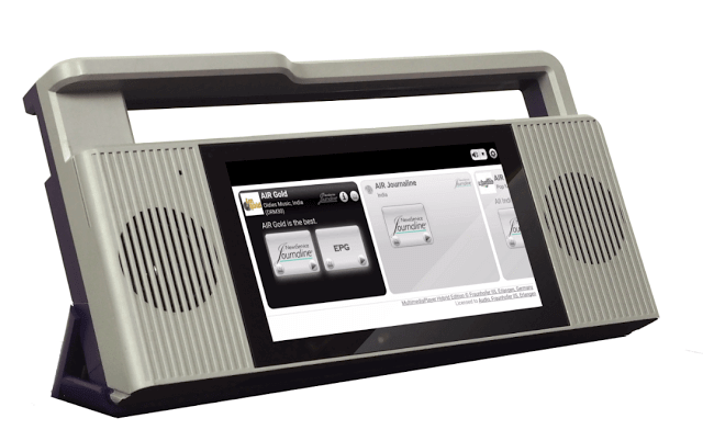
Since September 2016 we’ve been slowly hearing news about the PantronX Titus II portable SDR system, but as of yet nothing seems to have eventuated. The Titus II is essentially an Android touch screen tablet running their custom software, a set of speakers, an antenna and an SDR chip with 100 kHz to 2 GHz tuning range all in one portable system that has been estimated by them to retail for less than $100 USD. The main goal with the system is to provide low cost receivers for digital broadcast standards like DRM, DAB and DAB+ to try and boost their popularity.
Titus II receiver features include:
DRM in the AM bands (MW, SW, LW) and VHF bands (FM-band, VHF band-I, VHF band-III) with latest xHE-AAC audio codec.
DAB Classic/DAB+ (VHF band-III).
FM stereo with RDS (Service Signaling).
AM with AMSS (AM Signaling Service).
Integrated service list management and service selection.
DRM/DAB Data Apps: Text Messages, Dynamic Label/DL+, Journaline, (Categorized) Slideshow, EPG, Transparent File Transmission (e.g., for educational services), etc.
Remote Radio Hotspot: Built-in WiFi hotspot feature, which allows any mobile device with an HTML5 web browser to connect to the Titus II via Wi-Fi, select radio services, listening to aud (HTML5 audio streaming) and accessing all the DRM/DAB data apps.
Recording feature and Archiving interface to select existing recordings for playback.
Titus SDR, a division of PantronX, says the Titus II multi-standard digital radio receiver is ready for production.
The consumer software-defined radio digital receiver platform, which is the result of collaboration between Titus SDR/Patron X, Jasmin-Infotech, TWR, and Fraunhofer IIS, supports multi-standard radio reception, including DRM, DAB and DAB+ and core data applications. The system is based on a custom Android tablet platform, featuring multipoint touch, WiFi/Bluetooth and stereo sound.
Titus II units will be available as a stand-alone product from Titus SDR as well as from selected OEMs. Titus SDR explains that as a module, Titus II can serve as a full-featured basis for third-party product development, adding that PantronX provided the platform and RF expertise, while Fraunhofer IIS enabled the digital and analog radio features.
With latest xHE-AAC audio codec, Titus II supports DRM in the AM and VHF bands; DAB/DAB+; FM stereo with RDS; AM with AMSS; integrated service list management and service selection; DRM/DAB data apps; text messages and Journaline.
No news yet on exact release dates, but if you are interested you can sign up to their pre-order notification list at titusradio.com.
The Titus II
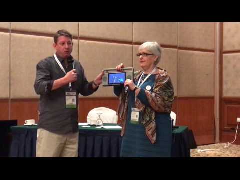
From YouTube we’ve also found a short video of them demonstrating the Titus II from DBS2017 back in March. Another video showing the interface up close can be seen here.
Live right now is CyberSpectrum #22, currently being held at the GNU Radio Convention in San Diego. Cyberspectrum is an often monthly meetup where SDR enthusiasts come from around the world to share their work. The video will be available offline once the stream is over too. But if watched live you can use the #cyberspectrum hashtag on Twitter, or join the #cyberspectrum on Freenode IRC to discuss the presentations live.
By day, Clayton is a security researcher at ecommerce company Shopify, and by night a GNU Radio enthusiast and amateur radio operator (VE3IRR). He’s worked on projects such as gr-dsd (digital voice), gr-qam (digital television), gr-elster (utility metering), gr-rds (radio data) and sdr-examples. Tonight he’ll tell you about his recent work on HD Radio.