Category: Other

GhostSDR: An RTL-SDR Based Ghost Box for SDR#

A "Ghost Box" or "Spirit Box" is a tool used by paranormal investigators to talk with spirits via the claimed electronic voice phenomenon (EVP). Some believers in paranormal activity theorize that electronic radio devices or EM fields are susceptible to manipulation by other worldly spirits, and thus this can be used as a communications method. A Ghost Box is a radio device that rapidly tunes through broadcast FM radio stations, hoping to catch EVP replies by spirits from questions asked. 

In the past we've seen that the RTL-SDR has been used for this purpose with the gqrx-ghostbox software. However as gqrx-ghostbox only runs on Linux, EVP researcher 'Capt Zeanie' decided to create 'GhostSDR' which is a ghostbox program that works with SDR# in Windows. The software interfaces with SDR# via the Remote Net SDR# plugin which allows SDR# to be controlled via a network connection. Note that when we tried to run it we got an invalid memory error, so it might still be a little buggy. If you have problems you can contact Zeanie over on our forums, where he has posted the following:

This is my version of a Spirit Box or Ghost Box but using a V3 instead of a complete handheld radio as these modified are quite expensive.

I use SDR# and the main application to interface with the V3, and I also use the Net Remote Plugin which allows me to control SDR# from my software.

A Ghost Box is a radio that is modified to quickly scan through the frequencies without stopping on an particular signal. So essentially it skips between frequencies. This supposedly help spirits be able to speak through the white noise etc. Any TV Paranormal show has one..

I have been researching EVP (Electronic Voice Phenomenon) and trying for over 2 years to see if EVP actually exists. As of yet after 100's of hours of recording on various equipment I have not had anything really come through. In EVP terms I am talking about Class A to Class B EVP's (ie loud and clear).

I started this research into EVP 2 years ago after my Father-in-law passed away at his home. A few months later Mother-in-law saw a man in a brown suit appear in her bedroom whilst getting into bed, after 10-15secs he just faded away. Now my Mother-in-law is trustworthy and does not lie, so I thought with my interest in the paranormal and my long experience with working in IT I thought I could try and see for myself and ended up being more interested in EVP's.

So to help me create a Ghost Box I have written GhostSDR

A pre-bought modified Ghost Box just usually scans through the AM or FM bands, whereas GhostSDR allow you to choose which frequencies you want to use, you are only limited to the capabilities of your chosen SDR Device (ie V3)

My software allows a user to create various frequency lists that has a starting Frequency, Ending Frequency, Skip frequency and bandwidth. ie Start at 72MHz, ending at 108MHz, skipping xxHz and using a user selectable bandwidth. It will sequential skip through the frequencies of be totally random (which modified handheld Ghost Boxes can not do)

There are few more features to add over time but I am trying this version for a few months before tweaking/adding things.

The software is probably quite similar to the SDR# frequency scanner plugin which 'shielaaliens' has used before as a ghostbox tool as well.
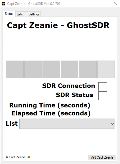
GhostboxSDR Interface

An Intuitive Tutorial on SDR, The Frequency Domain and IQ Data

Over on his website P. Lutus has written up a useful article that introduces us to some common SDR hardware (RTL-SDRs, upconverters and the HackRF), mentions some common SDR software, and then dives into some SDR theory explaining concepts like the frequency domain and IQ sampling.

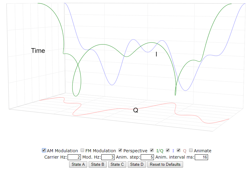
The theory sections in particular are explained quite intuitively with animated and interactive graphs that really help with visualizing the math. The explanations are short and not math heavy, so if you have half an hour you can learn some of the basic theory behind making SDRs work.

IQ Visualized on an interactive graph.
IQ Visualized on an interactive graph on P.Lutus' blog post.

DSP Illustrations: Learning DSP with a Soundcard SDR

DSP Illustrations is an online course that aims to explain complex digital signal processing (DSP) concepts visually instead of on a purely theoretic and mathematical level. Most of the content appears to be free, but some premium content requires payment.

One premium course that they've recently released is titled "Using your Soundcard as a Software-defined radio". In this course they use a standard PC sound to transmit (with the speakers) and receive (with a microphone) audio signals. All the DSP code is produced in Python and the course aims to walk you through all the concepts shown below.

  • baseband transmission of real-valued signals
  • passband transmission including up- and downconversion
  • modeling the audio channel as an LTI system for reproducable simulations
  • eye diagram drawing
  • symbol timing recovery
  • channel coding
  • definition and implementation of a frame structure, including header, payload and checksum
  • integration of the wireless transmission into a UDP data stream

Although the "SDR" isn't using radio frequencies, the exact same DSP concepts that apply with audio also apply to radio. So this can be a cheap way to get hands on DSP experience without the cost of needing to own a transmit/receive capable SDR.

This course costs about US$20, but the first three chapters are free.

Using a soundcard to study wireless communications.

Understanding the Fourier Transform: Video Tutorial from 3Blue1Brown

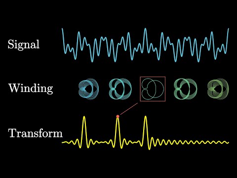
The Fourier Transform is a fundamental concept when it comes to digital signal processing (DSP) and thus understanding how software defined radios like the RTL-SDR work. It is the key bit of maths behind the RF/waterfall spectrum displays and frequency selection features used on your SDR software. In basic terms all the Fourier Transform does is take a signal (for example an RF signal from an antenna, or a sound sample), and break it down into its component frequencies. This allows us to see each individual frequency spike in the RF/waterfall spectrum display in programs like SDR# from the mash of signals that arrive at the antenna. But understanding how the Fourier Transform does this can be a little tricky to understand.

3Blue1Brown is a very successful YouTuber whose channel is all about explaining complex mathematical concepts in an animated and easy to digest format. His latest video explains the Fourier Transform, and is a great starting point for those trying to learn DSP concepts. He focuses on audio frequencies as that is the most intuitive, but the exact same concepts can be applied to radio frequencies.

But what is the Fourier Transform? A visual introduction.

RTL-SDR Module for the VCV Rack Modular Synthesizer

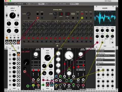
VCV Rack is an open source virtual modular synthesizer, which is software that can be used to create synth music or sounds. The interface is modeled after physical synthesizers called Euroracks. Recently, Jon Williams has ported rtl_fm to the VCV Rack plugin system which allows him to include live FM music in the synthesizer output. This can be used to create some interesting sounds which he demonstrates on the video that is shown below. The frequency tuning is 'voltage controlled', which simply means that it can be adjusted with a knob in the software.

The code is available on GitHub and is fully open source.

Outernet 3.0 Coming Soon: Free 30kbps – 100kbps satellite data downlink for news, weather, audio etc

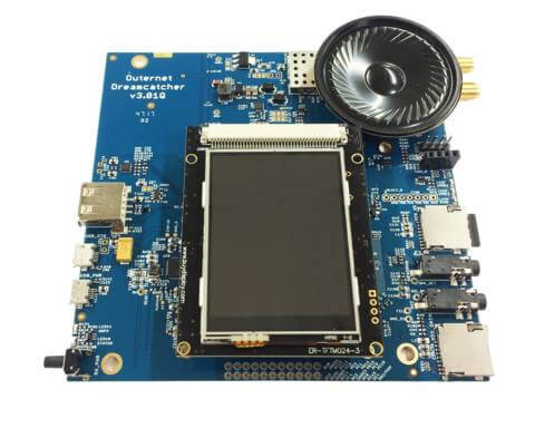
The new Outernet Dreamcatcher v3.01

Over the past few years we've posted quite a bit about Outernet who offered a free downlink of satellite data such as news, Wikipedia articles and weather updates that was able to be received with a small L-band patch antenna, LNA and an RTL-SDR dongle.

Recently we've seen news on their forums that Outernet is planning on discontinuing their L-band service, and instead opening up a new much more efficient Ku-band service. Unfortunately that means that RTL-SDRs and the previous Outernet L-band hardware will no longer be useful for the downlink, but the new service appears to offer several significant advantages.

Firstly the downlink data rate is much higher at 30kbps, with the plan to eventually go up to 100kpbs. That's 300MB - 1 GB a day which is a lot more compared to the previous L-band implementation that gave less than 20MB a day.

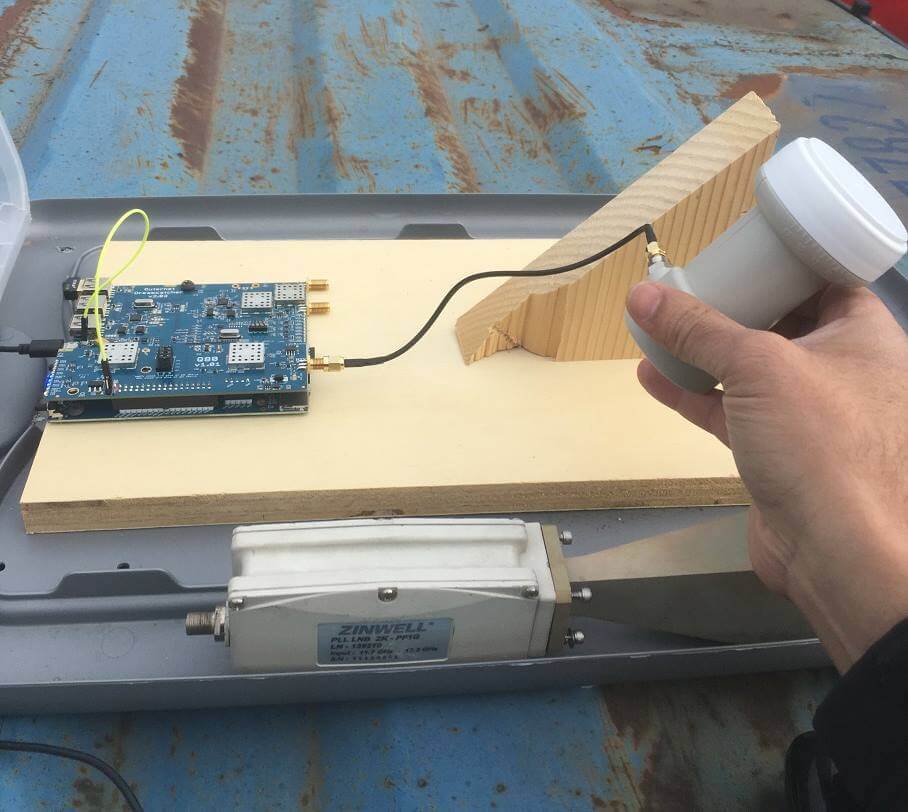
Secondly the hardware seems to be simplified as well. All that is needed is their new Dreamcatcher V3 receiver board and a small Ku-band LNB (11.7-12.75 GHz). They claim that no dish is required as the LNB pointed at the satellite by itself will work just fine. The first iteration of Outernet also used Ku-band satellites, but required a large dish antenna to receive it which was a major hurdle to user adoption. They now appear to have discovered a new way to broadcast in the Ku-band without the need for a dish.

Thirdly, moving to Ku-band means significant cost savings for Outernet allowing them to survive and continue with their free data service. From what we understand the L-Band satellite downlink service is extremely costly to run, whereas a Ku-band service is much cheaper. There are also cost savings for the user as Ku-band LNBs are very common hardware that can be found cheaply for $10 - $20 US.

About the new services that they can offer and the cost savings that they can achieve Syed the CEO of Outernet writes:

The fatter pipe [300MB - 1GB] makes a lot of things possible, one of which is a true radio broadcast. How about a national radio broadcast that isn't SiriusXM? Our new receiver will include a speaker; audio through the speaker while files download in the background. But more data is not the most important thing that comes out of all this. The real win is that leasing standard, commodity Ku bandwidth is far, far more cost effective than the few kilohertz we have on L-band. Long-term sustainability of a free broadcast is no longer the financial burden that it once was--especially considering how much more interesting the service becomes.

There is no concrete hardware release date just yet, but on the forums Syed estimates mid-Jan. You can sign up to the Outernet mailing list on their buy-now page to be emailed when the new hardware is released. In the forums Syed also writes that the target price for the hardware is $99 US, with the intention to provide lower cost options in the future. Of course it might still be possible to DIY your own unit just like it was with the previous Outernet iterations.

We're really looking forward to this and think that this is what will finally make Outernet a very popular and useful service!

The Outernet 3.0 prototype setup

RFSim99 for Modern Windows Versions: Free RF Simulation Tool

RFSim99 is an old but still very useful piece of free software for designing and simulating RF circuits such as filters, attenuators, matching circuits, RF components with S-parameters and so on. It is not a high end tool, but is more than good enough for hobbyist and ham level designs.

One issue up until recently with RFSim99 was that it was so old that it would only run on Windows XP computers. To run on a modern PC you needed to use a virtual machine, or the Windows built in XP emulation, which was only available on Professional/Ultimate Windows versions and has since been discontinued in Windows 10.

However, we have just found AD5GG's blog where earlier in the year he posted a standalone version that actually works in modern Windows versions (7, 8, 10) without the need for any virtual machines.

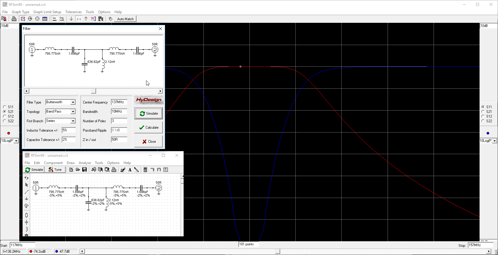
RFSim99 is fairly simple to learn. Just place down two measurement ports (in/out) and lay down your RF components on the grid. Then connect them up with a wire and place grounds. Click on the simulate button to see a graph of the response and return loss. There are even built in calculators in the Tools menu which can automatically design and simulate filters for you.

Designing a simple filter in RFSim99

Leif Compares various SDRs including the RSP1, Airspy with SpyVerter, Airspy HF+, FDM-S1, IC706, Perseus

Over on YouTube Leif 'sm5bsz' has uploaded a video that does a lab comparison of various SDRs on the market now including the new Airspy HF+. Leif is known for providing excellent lab based technical reviews of various SDR products on his YouTube channel.

The first video compares the Airspy HF+ with the Perseus SDR. The Airspy HF+ is a new high performance yet low cost ($199 USD) HF/VHF specialty SDR. The Perseus is an older high performance direct sampling HF only SDR, although it comes at the high price of about $1000 USD.

In his tests Leif tests both units at 14 MHz and finds that the HF+ has about 15 dB better sensitivity compared to the Perseus (NF = 7dB vs 22dB). On the other hand the Perseus has about 23 dB better dynamic range compared to the HF+ (Dynamic Range = 127 dBc/Hz vs 150 dBc/Hz), although he notes that a blocking transmitter needs to have a very clean signal to be able to notice this difference which would be unlikely from Amateur transmitters. 

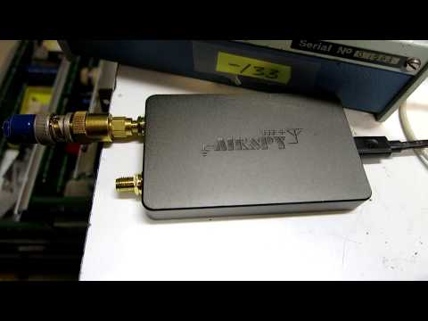
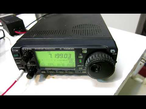
In the next two videos Leif compares multiple SDRs including the SDRplay RSP1, FUNcube Pro+, Airspy with Spyverter, Airspy HF+, Afedri SDR-Net, ELAD FDM-S1, ICOM IC-706MKIIG and Microtelecom Perseus at 7 MHz.

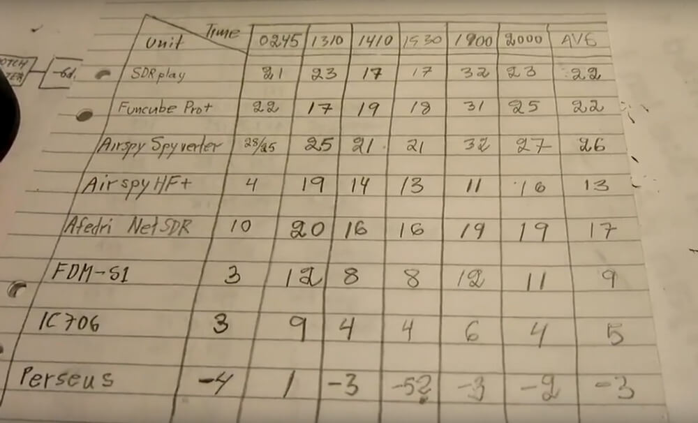
In the RX4 video Leif compares each SDR on dynamic range at 7 MHz. If you want to skip the testing parts, then the discussion of the results in the RX4 tests start at 1:03:00. A screenshot of the results is also shown below. The SDRs are ranked based on their average results over multiple measurements at different times which is shown in the last column. A lower value is better, and the value represents how much attenuation needed to be added to prevent the SDR from overloading and causing interference in his setup.

Dynamic Range Test Rankings

In the RX5 video the results start at 54:20:00. In this video he compares the SDRs with real signals coming in from his antenna at 7 MHz. He tests with the antenna signal wide open, with a 4.5 MHz LPF (to test out of band blocking performance), and with a bandpass filter at 7 MHz. Again lower values are better and the values indicate the amount of attenuation required to prevent overload. The Perseus is used as the reference benchmark. He also tests reciprocal mixing later in the video.

RX5 Results
RX5 Results