The PortaPack is a US$220 add-on for the HackRF software defined radio (HackRF + PortaPack + Accessory Amazon bundle) which allows you to go portable with the HackRF and a battery pack. It features a small touchscreen LCD and an iPod like control wheel that is used to control custom HackRF firmware which includes an audio receiver, several built in digital decoders and transmitters too. With the PortaPack no PC is required to receive or transmit with the HackRF.
Of course as you are fixed to custom firmware, it's not possible to run any software that has already been developed for Windows or Linux systems in the past. The official firmware created by the PortaPack developer Jared Boone has several decoders and transmitters built into it, but the third party 'Havoc' firmware by 'furrtek' is really what you'll want to use with it since it contains many more decoders and transmit options.
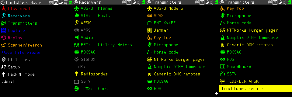
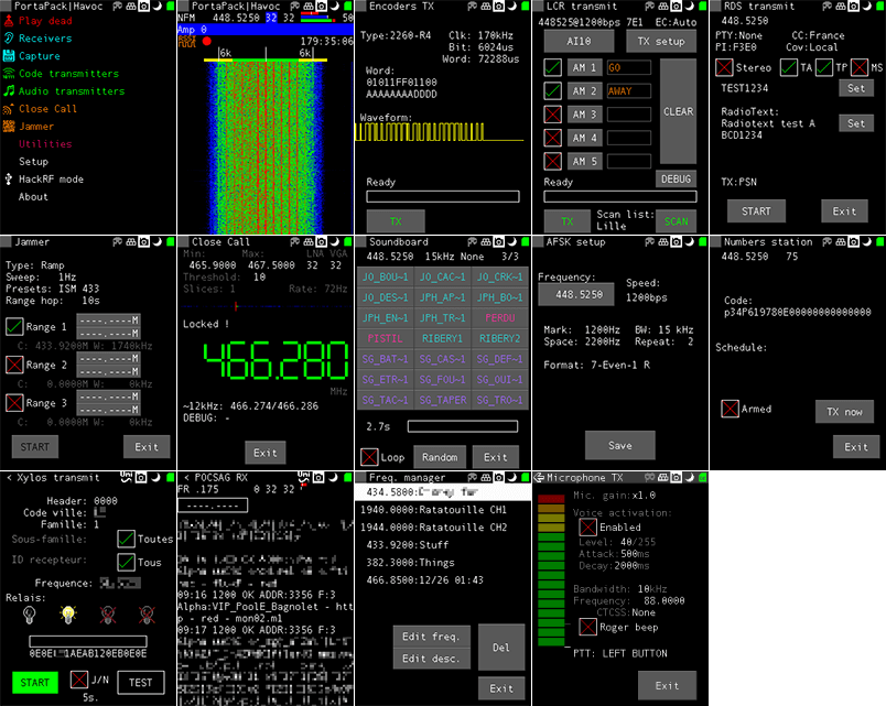
As of the time of this post the currently available decoders and transmit options can be seen in the screenshots below. The ones in green are almost fully implemented, the ones in yellow are working with some features missing, and the ones in grey are planned to be implemented in the future. Note that for the transmitter options, there are some there that could really land you in trouble with the law so be very careful to exercise caution and only transmit what you are legally allowed to.
Some screenshots from the HackRF Portapack Havoc FirmwareMore Havoc firmware screenshots from the GitHub page.
Although the PortaPack was released several years ago we never did a review on it as the firmware was not developed very far beyond listening to audio and implementing a few transmitters. But over time the Havok firmware, as well as the official firmware has been developed further, opening up many new interesting applications for the PortaPack.
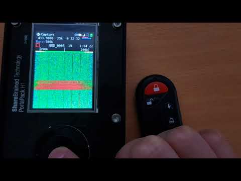
Doing a replay attack on a wireless keyfob using the PortaPack.
Testing the PortaPack with the Havoc Firmware
Capture and Replay
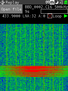
One of the best things about the PortaPack is that it makes capture and replay of wireless signals like those from ISM band remote controls extremely easy. To create a capture we just need to enter the "Capture" menu, set the frequency of the remote key, press the red 'R' Record button and then press the key on the remote. Then stop the recording to save it to the SD Card.
Now you can go into the Replay menu, select the file that you just recorded and hit play. The exact same signal will be transmitted over the air, effectively replacing your remote key.
We tested this using a simple remote alarm system and it worked flawlessly first time. The video below shows how easy the whole process is.
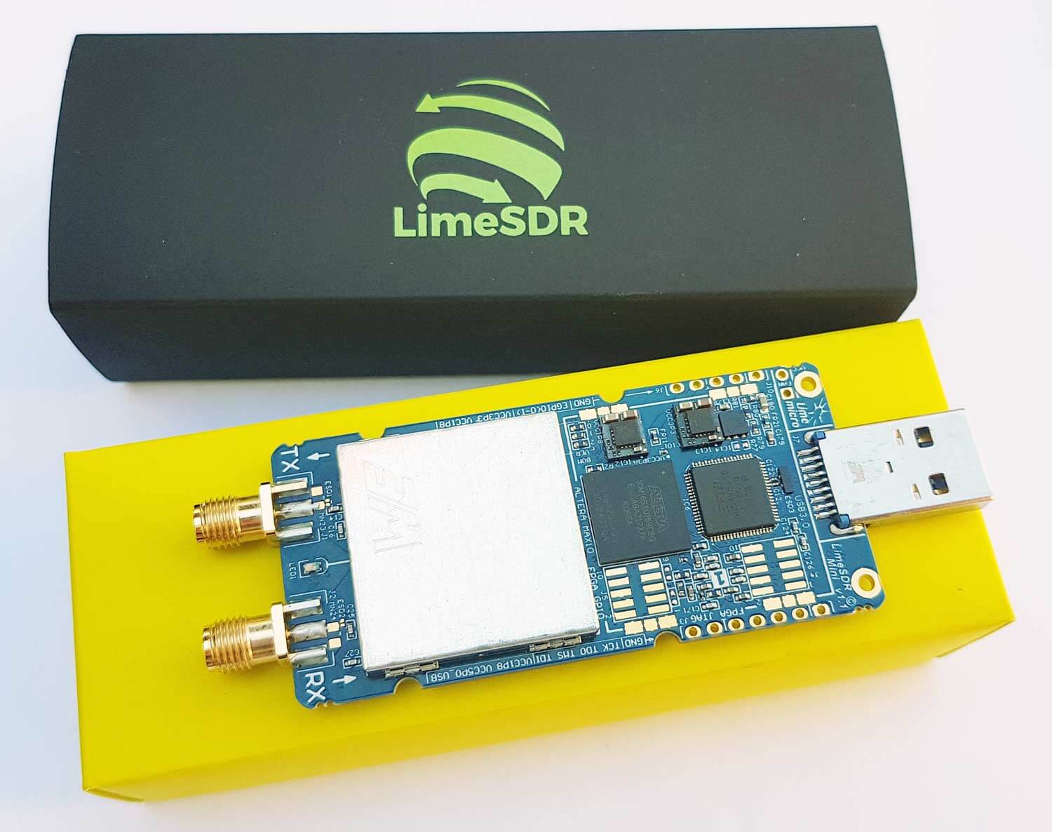
The LimeSDR Mini has now started shipping out to backers, and we received our unit just last week. The LimeSDR Mini is the smaller version of the full sized LimeSDR which was released early last year in 2017. The standard LimeSDR has a frequency range of 100 kHz – 3.8 GHz, bandwidth of up to 61.44 MHz, 12-bit ADC and 2 x 2 RX/TX channels. In comparison the new LimeSDR mini has a slightly restricted frequency range of 10 MHz – 3.5 GHz, and half the maximum bandwidth at 30.72 MHz. The mini also only has 1 x 1 TX/RX channels. The price is however much less coming in at US$139 for the mini and US$299 for the standard LimeSDR.
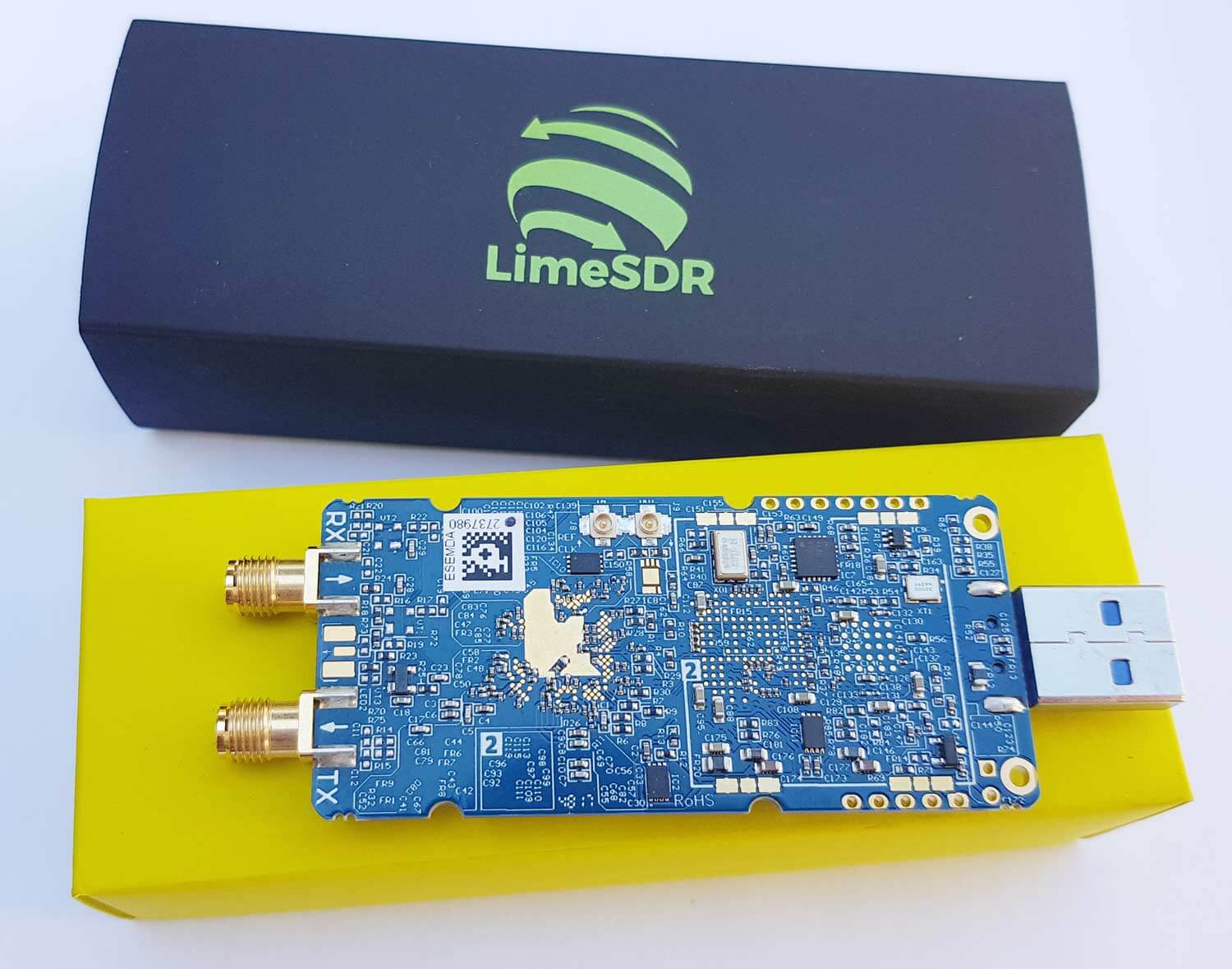
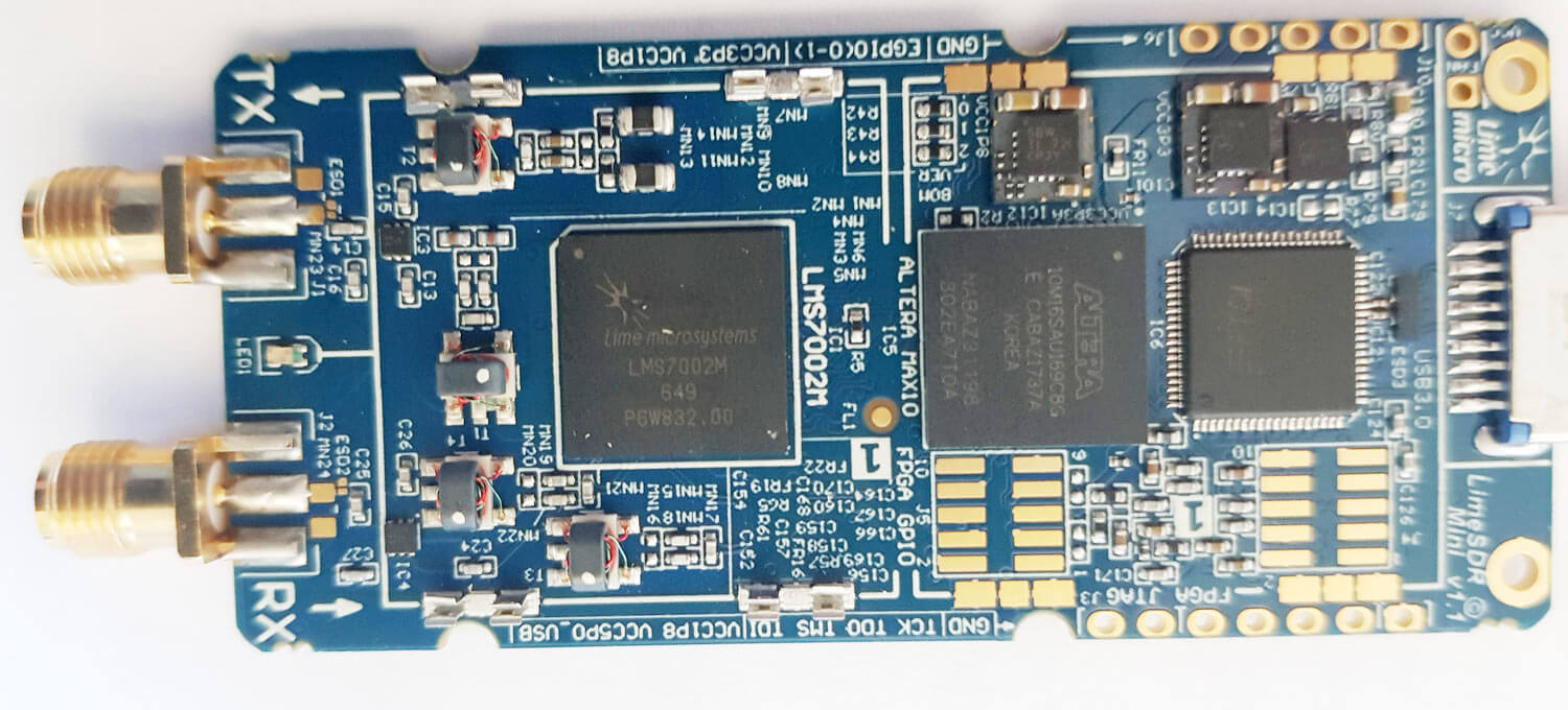
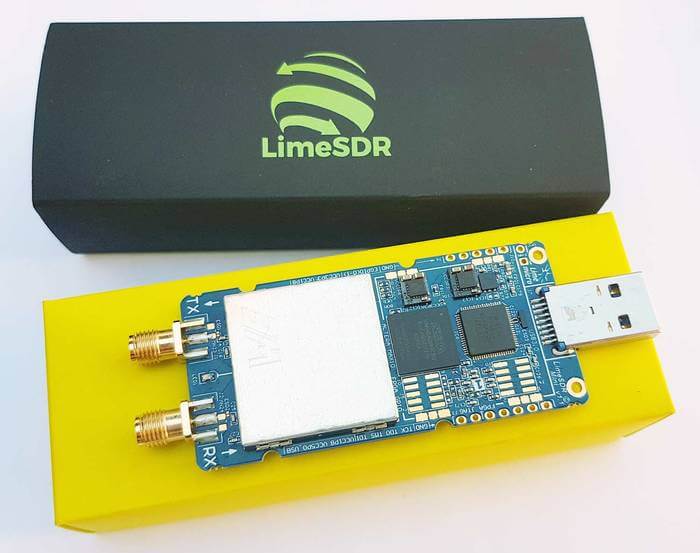
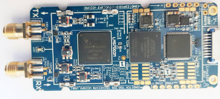
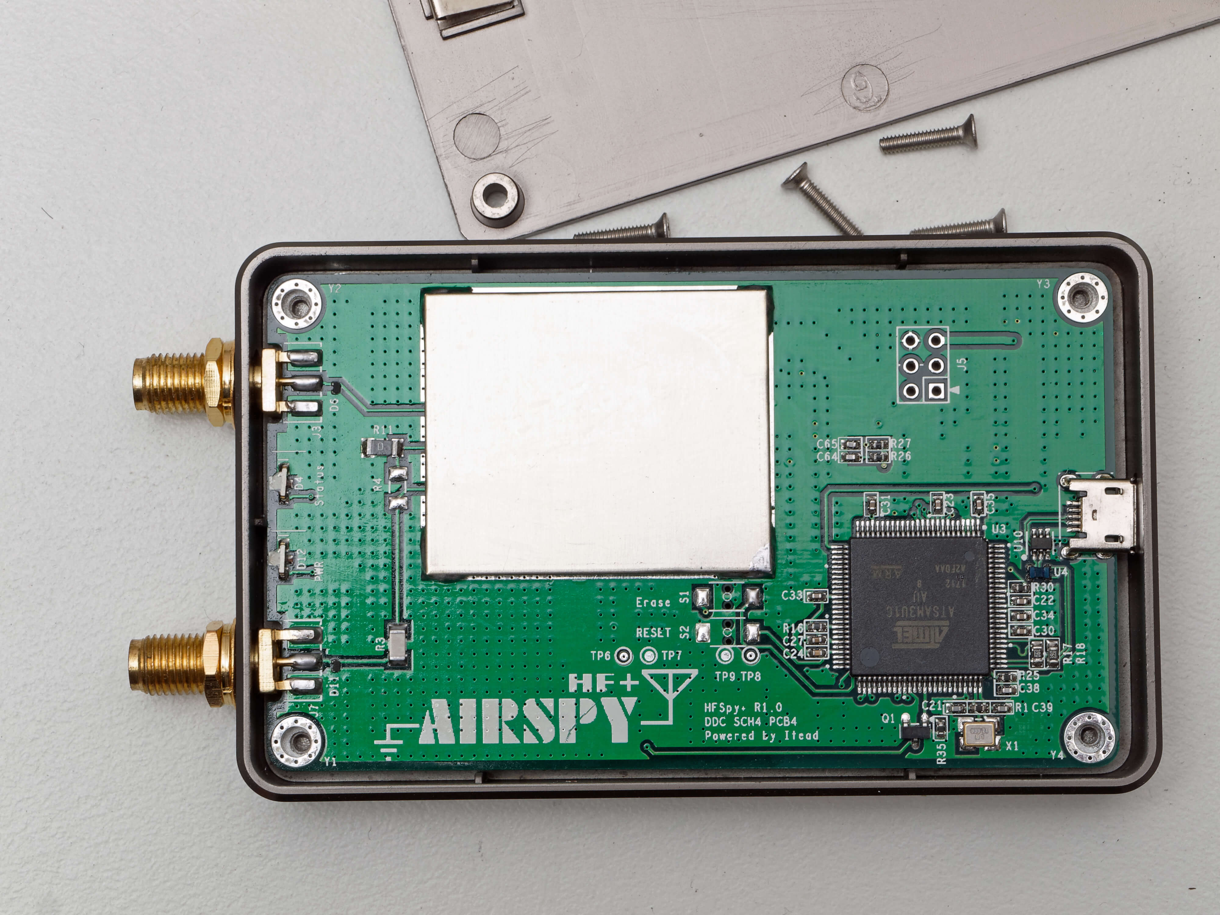
The LimeSDR Mini came in a small black box inside an anti-static bag. No accessories like antennas are included in the package. The PCB comes without any enclosure, but an enclosure can be ordered as an additional extra. The size of the PCB is similar to an RTL-SDR, but a little wider. The RF sensitive components are covered with a shielding can. Removing the can reveals the main Lime System RF chip, the LMS7002M, as well as several RF transformer matching circuits.
One end of the PCB has a standard USB-A connector, whilst the other end has two SMA ports, one for receiving and the other for transmitting.
The PortaPack is a US$220 add-on for the HackRF software defined radio (HackRF + PortaPack + Accessory Amazon bundle) which allows you to go portable with the HackRF and a battery pack. It features a small touchscreen LCD and an iPod like control wheel that is used to control custom HackRF firmware which includes an audio receiver, several built in digital decoders and transmitters too. With the PortaPack no PC is required to receive or transmit with the HackRF.
Of course as you are fixed to custom firmware, it's not possible to run any software that has already been developed for Windows or Linux systems in the past. The official firmware created by the PortaPack developer Jared Boone has several decoders and transmitters built into it, but the third party 'Havoc' firmware by 'furrtek' is really what you'll want to use with it since it contains many more decoders and transmit options.
As of the time of this post the currently available decoders and transmit options can be seen in the screenshots below. The ones in green are almost fully implemented, the ones in yellow are working with some features missing, and the ones in grey are planned to be implemented in the future. Note that for the transmitter options, there are some there that could really land you in trouble with the law so be very careful to exercise caution and only transmit what you are legally allowed to.
Some screenshots from the HackRF Portapack Havoc FirmwareMore Havoc firmware screenshots from the GitHub page.
Although the PortaPack was released several years ago we never did a review on it as the firmware was not developed very far beyond listening to audio and implementing a few transmitters. But over time the Havok firmware, as well as the official firmware has been developed further, opening up many new interesting applications for the PortaPack.
Doing a replay attack on a wireless keyfob using the PortaPack.
Testing the PortaPack with the Havoc Firmware
Capture and Replay
One of the best things about the PortaPack is that it makes capture and replay of wireless signals like those from ISM band remote controls extremely easy. To create a capture we just need to enter the "Capture" menu, set the frequency of the remote key, press the red 'R' Record button and then press the key on the remote. Then stop the recording to save it to the SD Card.
Now you can go into the Replay menu, select the file that you just recorded and hit play. The exact same signal will be transmitted over the air, effectively replacing your remote key.
We tested this using a simple remote alarm system and it worked flawlessly first time. The video below shows how easy the whole process is.
The LimeSDR Mini has now started shipping out to backers, and we received our unit just last week. The LimeSDR Mini is the smaller version of the full sized LimeSDR which was released early last year in 2017. The standard LimeSDR has a frequency range of 100 kHz – 3.8 GHz, bandwidth of up to 61.44 MHz, 12-bit ADC and 2 x 2 RX/TX channels. In comparison the new LimeSDR mini has a slightly restricted frequency range of 10 MHz – 3.5 GHz, and half the maximum bandwidth at 30.72 MHz. The mini also only has 1 x 1 TX/RX channels. The price is however much less coming in at US$139 for the mini and US$299 for the standard LimeSDR.
The LimeSDR Mini came in a small black box inside an anti-static bag. No accessories like antennas are included in the package. The PCB comes without any enclosure, but an enclosure can be ordered as an additional extra. The size of the PCB is similar to an RTL-SDR, but a little wider. The RF sensitive components are covered with a shielding can. Removing the can reveals the main Lime System RF chip, the LMS7002M, as well as several RF transformer matching circuits.
One end of the PCB has a standard USB-A connector, whilst the other end has two SMA ports, one for receiving and the other for transmitting.
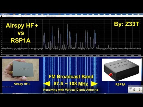
Frequent reviewer of SDR products Mile Kokotov has just uploaded on his YouTube channel a new video where he compares the Airspy HF+ against the SDRplay RSP1A on FM broadcast reception.
At first Mile compares the two against strong broadcast stations, and then later compares them on weak DX stations surrounded in amongst other strong stations. With the strong stations a difference between the two radios is impossible to detect. But with the weaker stations that are surrounded by strong signals the Airspy HF+ has the edge with it's higher dynamic range and sensitivity.
Mile writes:
In this video I am comparing two popular SDR-Receivers (Airspy HF+ and SDRplay RSP1A) on FM Broadcast Band.
I have made few recordings with every receiver with the same antenna trying to set the best SNR = signal-to-noise ratio.
My intention was to ensure the same conditions for both SDR`s in order to make as fair as possible comparison.
No DSP enhancing on the SDR`s was used.
Antenna was Vertical Dipole.
When receiving signals are strong enough, You should not expect the difference between most receivers to be very obvious!
If you compare one average transceiver (which cost about $ 1000 USD) and top class transceiver which cost ten times more, the difference in receiving average signals will be very small too. Almost negligible! But when you have difficult conditions, the very weak signal between many strong signals, than the better receiver will receive the weak signal readable enough, but cheaper receiver will not. Today it is not a problem to design and produce the sensitive receiver, but it is far more difficult to design and produce high dynamic receiver for reasonable price! The Airspy HF+ and RSP1A are very very good SDR-receivers. They have different customers target and have strong and weak sides. For examle Airspy HF+ has better dynamics in frequency range where it is designed for, but RSP1A, on the other hand, has broadband coverage...
Airspy HF+ vs SDRplay RSP1A Comparison on FM Broadcast Band
Over on YouTube user Laboenligne.ca has uploaded a review of the ColibriNANO. If you didn't already know the ColibriNANO is a low cost but high performance direct sampling receiver designed for the HF bands. Currently it costs $269.95 US from nsiradio. It now competes almost directly with the recently released Airspy HF+ which is a lower cost $199 unit with similar performance specifications.
Laboenligne.ca's review initially goes over the specs of the ColibriNANO and usage of the free ExpertSDR2 software that is used with the ColibriNANO. He also shows how the ColibriNANO can be connected to a Raspberry Pi 3 and used remotely over the internet. This is similar to the Airspy's SpyServer, but the difference is that ColibriNANO's server interface works in a browser via HTML5, so it can be used on any platform including mobile devices. Of course the ExpertSDR2 software can also be used to connect to the server as well. In his review Laboenligne.ca notes that he is very impressed with the remote web interface and has set up a public server demonstration of his ColibriNANO available at vpn.laboenligne.ca. He notes that if there is no reception to try again later, as he may be using the antenna on another radio.
The ColibriNANO SDR receiver review (English version)
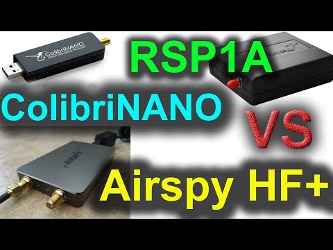
Over on his YouTube Channel Mile Kokotov has uploaded a video that compares three mid priced SDRs: the Airspy HF+, the SDRplay RSP1A and the ColibriNANO. Each SDR is compared on several ALPHA and NBD morse code stations which exist in his tests from between 14 kHz to 474 kHz. He writes:
In this video I am comparing three SDR-Receivers. I have made few recordings with every receiver with the same antenna and choose the best one (one with the best SNR = signal-to-noise ratio). My intention was to ensure the same conditions for all three SDR`s in order to make as fair as possible comparison. For example, I was set the frequency span displayed on the window to be as same as possible for all three receivers. The vertical axis for the signal stregth, was set to be equal (in decibels) too.Airspy HF+ and ColibriNANO was set to their minimum sample rate (48 kHz). RSP1A was set to minimum sample rate (2 MHz and 8 decimation).
No DSP enhancing on the SDR`s was used except APF (Audio peak filter) on ColibriNANO (I forgot to swith off).
The differences between each receiver as very difficult to detect as only really challenging signal conditions will really set them apart. Mile also added in a comment:
You should not expect the difference to be very obvious! If you compare one average transceiver (which cost about $ 1000 USD) and top class transceiver which cost ten times more, the difference in the receiving the average signals will be very small too. Almost negligible! But when you have difficult conditions, the very weak signal between many strong signals, than the better receiver will receive the weak signal readable enough, but cheaper receiver will not. Today it is not a problem to design and produce the sensitive receiver, but it is very difficult to design and produce high dynamic receiver for reasonable price! The Airspy HF+ and RSP1A are very very good SDR-receivers. They have different customers target and have strong and weak sides. For example Airspy HF+ has better dynamics in frequency range where it is designed for, but RSP1A, on the other hand, has broadband coverage...
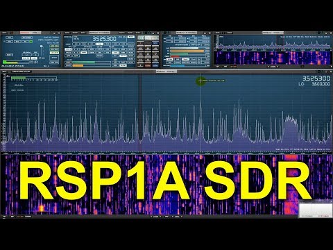
Like the HF+ mentioned in the previous post, the RSP1A SDR was also recently released and has now had enough time in the wild to gather up a few online reviews. If you didn't already know, the $99 US SDRplay RSP1A is a revision of the RSP1. Compared to the RSP1 it significantly improves the filtering and front end design. We have our own review of the RSP1A unit here, and we mentioned some early reviews from other bloggers in this linked post. Below we post some of the new reviews that we are aware of which have come out since our last post.
Robert Nagy
In his video Robery Nagy does a full review of the RSP1A including a 15 minute primer on SDRs. This is great if you want a brief introduction to understanding how SDRs actually work, and what performance measures are important for comparing them. In the second half of the video Robert shows how to use SDRuno and shows the RSP1A in action.
SDRplay RSP 1A Review and SDR Primer
Mile Kokotov
In this video Mile Kokotov demonstrates the HF+ receiving a CW contest in his home country of Macedonia with the RSP1A and a full-size half wave resonant dipole antenna. He writes:
CQ World Wide DX Contest (CW) receiving in Macedonia with SDRplay RSP1A SDR-receiver and SDRuno software on 80m-Band with full-size half-wave (40 meters long) resonant dipole antenna.
Contest conditions are always big challenge to any receiver dynamics. Here you can see only 60 kHz wide frequency spectrum fulfilled with many competitor stations "fighting each other". In addition, there are local radio-station (only 1 km from my place) with huge signal...
RSP1A SDR receiver and SDRuno software - CQ World Wide DX Contest (CW) 2017
The Radio Hobbyist
In The Radio Hobbyist's video on YouTube Rick (VE3CNU) unboxes his RSP1A and shows the setup and download of SDRuno. He then goes are demonstrates reception on various signals.
Why Everyone's Upgrading From RTL SDRs
icholakov
In icholakov's video on YouTube he compares the older RSP1 with the newer RSP1A on medium wave and shortwave reception using a dipole in a noisy suburban RF setting. Differences are hard to detect as the signals he tests with are not likely to cause any overloading issues, but the RSP1A does seem to have a slightly less noise.
The new Airspy HF+ SDR receiver has now been shipped to multiple customers and reviewers, and new reviews are coming online fast. If you weren't already aware, the Airspy HF+ was a hotly anticipated low cost, but high performance HF speciality SDR receiver. The claims are that it can compete with the high end $500 US+ units. We have our own review of an early model here. Below are some new reviews that we are aware of.
Nils DK8OK's photo of the Airspy HF+.
Nils Schiffhauer - DK8OK
On his blog Nils presents us with a comprehensive set of audio recordings comparing the $525 US Elad FDM-S2 with the $199 US Airspy HF+. He compares the two receivers on various shortwave broadcast stations, time stations, and an airport VOLMET. The recordings are identical, with the two radios recording the same signals simultaneously via a splitter.
Both receivers produce excellent results so you will probably need headphones and keen ears to be able to tell the difference.
Mile Kokotov
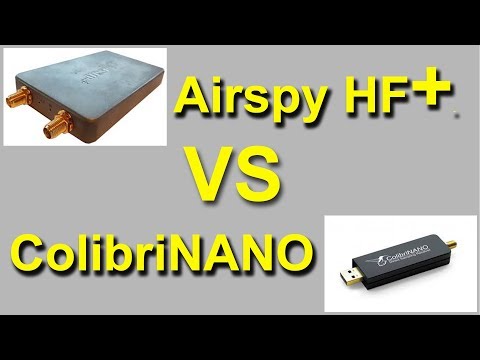
In this review YouTube video Mile Kokotov presents a comparison of the Airspy HF+ vs. the ColibriNANO, a similarly specced SDR dongle. He writes:
In this video I am comparing two high quality SDR Receivers: Airspy HF+ and ColibriNANO. They both have 16 bit Analog-to-Digital Converter. Comparison was made with the same overall conditions.
For example, both receivers was set with equal size spectrum windows, with the same amount of decibels in their scale, and the same high of the spectrum windows. ColibriNANO has LNA gain slider which was set to maximum SNR.
Airspy HF+, on the other hand, has no LNA gain control. The SV2HQL/Beacon was chosen as a test signal on 3579.32 kHz (on 80m band)
Antenna is half-wave resonant Dipole (40 meters long) for 80m band.
In the second part of the video I was inserted 27 dB external Attenuator on both receivers. ColibriNANO automatically increased the LNA gain and sets itself to maximum SNR. With this amount of attenuation, The Airspy HF+ noise floor level was at about the same place in spectrum window like ColibriNANO, Unlike in the first part of the video, when no external attenuator was used.
Both SDR-receivers are very good! Which is better? I leave on you to judge...
Airspy HF+ vs ColibriNANO Comparison on 3.579 MHz
Mile also does a second test with his HF+ and an active Mini-Whip antenna. He writes:
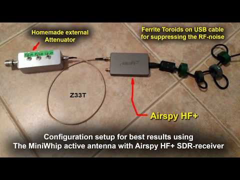
Airspy HF+ is superb High-Dynamic HF and VHF SDR-receiver and I am impressed with it. In order to minimize possible negative effect on signal path from antenna connector to tuner input, Airspy HF+ has no internal attenuator. Developers takes in account that this SDR-receiver has enough dynamic range that is very difficult to overload it. Actually it is true for most cases. But, if we want to use some type of active antenna (with internal amplification) like Mini-Whip Active Antenna for example, it is good idea to add an external attenuator between antenna and receiver HF-input connector, in order to have opportunity to lower the signal level from the active antenna, and to avoid possible overload issues. In this video I am presented some scenario (receiving MW AM band) when my homemade external step-attenuator is more than welcome! By the way, the external step-attenuator is very easy to made in almost no money. All you need is 9 resistors, three switches and one metal box) I have 5.5 dB switch, 10.5 dB switch and 22 dB switch. It can be set for 8 various combinations: 0, -5.5 dB, -10.5 dB, -16 dB, -22 dB, -27.5 dB, -32.5 dB and -38 dB.
You can see on this video that the AM Broadcast signal from Macedonian Radio on 810 kHz is very strong. The Antenna is about 30 km from my house. It is self standing huge 185 meters high vertical antenna, radiating enormous RF-power, so I have to use my homemade attenuator I mentioned it before.
Airspy HF+ SDR Receiver with Mini-Whip Active Antenna and External Attenuator
The SWLing Post Blog
Here Thomas of the SWLing post blog has posted a brief review of his HF+ unit. He notes how the HF+ is very compact, with a durable enclosure and how easy it was to set up with it being completely plug and play. So far Thomas hasn't fully evaluated the performance, but his first impressions are good.
Adam 9A4QV
In his two videos Adam doesn't directly review the Airspy HF+, but he does show some pretty impressive reception with his Skyloop antenna.
CQWW-2017 the end of the contest AirspyHF+
CQWW-2017 using AirSPY HF+ and 250 feet long skyloop antenna
Yesterday the SDRplay team released the $99 US RSP1A, which is a revision of the RSP1A. In this post we present a review comparing its performance against the older RSP1 and the currently selling $169.95 US RSP2. We aim to mainly show demonstrations of improvements that we've found on the RSP1A in areas where we discovered problems on the RSP1 or RSP2.
Discussion of Improvements
First we present a discussion on the improvements made.
TCXO: The first noticeable improvement is that the RSP1A now comes with a 0.5PPM TCXO. This was one of the main criticisms of the RSP1 as the RSP1 only came with a standard oscillator which can drift as the temperature changes. But as mentioned in our previous review that included the RSP1, the drift was fairly small after warmup due to the good heat dissipation of the large PCB, and the relatively low power usage and thus less heating of the Mirics chips used on RSP units. Nevertheless, a TCXO is a good upgrade and brings it back in line with most low cost SDRs on the market now.
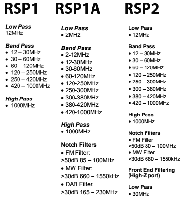
Enhanced RF Preselectors + Notches: Strong out of band signals can overload an SDR causing problems like imaging and reduced sensitivity. Preselectors are RF filters which help to filter out unwanted signals for the band that you are listening to.
The RSP1 had 8 preselector bands and the RSP1A brings this number up to 12, which is even more than the 10 preselectors on the RSP2.
In testing we found that the new preselectors certainly do help out a lot. The new 2 MHz low pass and 2 - 12 MHz certainly help to reduce interference from the MW broadcast AM band. Changes in the VHF filters reduce problems from strong broadcast FM and DAB stations. The filters have also been sharpened considerably making the existing filters even more effective. The RSP-1 in some cases suffered quite severely from out of band signal interference, and the RSP-2 made it a bit better, but the RSP-1A solves the interference problem much more.
The new FM/AM and DAB notch filters also do a good job at notching out these often problematic very strong signals.
Preselectors on the RSP1, RSP1A and RSP2
Improved LNA Architecture: In the RSP1 the front end LNA could only be turned on or off. Turning it on reduces the noise figure and improves performance, especially at UHF frequencies. The single gain step was problematic as often the LNA could overload on strong signals if turned on. The RSP1A introduces a gain control block which allows the LNA to have variable gain steps.
This new architecture helps to maximise the dynamic range of the RSP1A, thus reducing overloading.
Extended frequency coverage down to 1kHz: The lower limit of the RSP1 was 10 kHz, so really low LF reception is now available on the RSP1A.
Bias-T: Just like with the RSP2, the bias-t allows you to power external devices over the coax cable. Such as remote LNAs, switches etc. Running a good LNA next to the antenna is optimal, as this helps push signals through the coax cable losses.
RF Shielding: Like the RSP2 the plastic case is now spray painted with metallic paint on the inside. This works almost as well as a full metal case to shield from unwanted signals entering directly through the PCB, instead of through the antenna. We do still notice some leakage making its way in through the coax shield, but it is relatively minor with the shielding.
ADC Resolution Increased to 14-bits: The RSP1A uses the same ADC chip as the RSP1, but now has unlocked 14-bit ADC capability for bandwidths below 6 MHz thanks to onboard decimation and oversampling. So now 14-bit data comes directly into the PC if using a bandwidth below 6 MHz. Further decimation can still be achieved within software like SDRuno.
A higher bit ADC can improve dynamic range, meaning that strong signals are less likely to overload the SDR.
We asked SDRplay how 14-bits was achieved with the same chips used by the RSP1 and they explained that it is through oversampling and decimation onboard the chip. They also wrote the following technical reply which is a very good read (collapsed as the reply is quite long, click on "Read the Reply" to expand):
[expand title = "READ THE REPLY"]
The ADCs on the MSi2500 use a sigma-delta topology where a highly oversampled multi-bit ADC uses decimation filtering to provide the desired resolution. As the original spec for the MSi2500 called for 12 bit resolution, the fact that the converter was capable of delivering 14 bits for final sample rates of less than 6.048 MHz was ignored. Working with the Mirics team, we have been able to unlock the extra two bits of resolution that the MSi2500 was always capable of delivering. Using sample rates above 6.048 MHz, the ADC defaults back to 12 bit resolution.
They also explained:
If we take an 8 bit ADC for example, we can expect around 48 dB of instantaneous dynamic range. This will most likely be far lower than that achievable from the RF front end whose dynamic range will be influenced by factors such as noise figure, intermodualtion, cross modulation and synthesizer phase noise (reciprocal mixing). A decent tuner front end should be capable of delivering 65-70 dB of instantaneous dynamic range, which is also roughly what you can expect from a 12 bit ADC. In other words, we believe that in the RSP1, the instantaneous dynamic range of the tuner and ADCs were approximately the same. The limitation that the RSP1 had was because of the single gain step in the LNA, it was not always possible to utilise the available dynamic range in the most effective way. The RSP1A gives much greater (and finer) control over the RF gain and this allows for better alignment of the signal level into the tuner to better exploit the available dynamic range. In our tests in the broadcast FM band, we believe that the RSP1A gives around 10 dB more ‘usable’ dynamic range than the RSP1. In other words, if we combine multiple controlled modulated signals (for RF signal generators), with real weak off-air signals, the RSP1A is capable of handling interferers that are around 10 dB greater than the RSP1. Benchmarking against other products, in our tests, the RSP1A seems to give better performance now than anything else in the same price range, both in terms of sensitivity and in terms of in-band overload performance.
The RSP1 always gave very good sensitivity but in optimising it in this way, we gave up some performance in terms of in-band overload performance. Our objective with the RSP1A was to address this without sacrificing sensitivity.
Now, going back to the issue of 14 bits vs 12 bits and instantaneous dynamic range. If we increase the ADC dynamic range from 12 to 14 bits, then the ADC dynamic range should no longer influence the performance of the receiver. Indeed, it is our view, that for any receiver that needs to use a tuner as part of the front end (and any receiver that operates across the frequency range of the RSP will have to use a tuner for the foreseeable future), there is little benefit to be gained with ADC resolutions in excess of 14 bits, as to utilise the extra dynamic range that a higher resolution ADC can give, a much higher performance tuner would be required. Tuner technology has come a very long way in the last 10-15 years and the performance of modern integrated devices is actually very good. To get 12 dB of better dynamic range from a tuner is extremely difficult and can really only be achieved by using very much greater levels of power and esoteric semiconductor technologies. One possible area where you might see better performance is where you have multiple strong interfering signals to the extent that the RF gain needs to be turned down to such a level that the ADC quantisation noise effectively limits the noise floor of the receiver. In this case, you ought to see improved performance in 14 bit mode when compared to 12 bit mode, but please note that the improvement may only be a few dBs in the weak signal reception. If the noise floor of the receiver is still limited by the external LNA, then improved ADC dynamic range will give no perceptible improvement whatsoever.
A direct sampling receiver that does not use a tuner should in principle allow greater dynamic range than one that does, but in practice any direct sampling ADC needs some form of external low noise amplification to ensure a reasonable noise figure and the dynamic range (noise, intermodulation performance etc) of this external amplification block becomes a limiting factor. This is certainly true at VHF and above. At HF, as you will be well aware, the receiver noise figure is not really very important because the atmospheric noise floor is so high. In principle, you might therefore think that our best approach would be to bypass the tuner and use the decimated 16 bit performance of our ADCs. This would still give an effective receiver bandwidth of 375 kHz with 16 bit performance. The reality though is that the real dynamic range of signals coming into the antenna is limited by propagation conditions and atmospheric noise. It is rare to find signals that are above the atmospheric noise floor that vary by more than 60 dB. In practical terms, we believe that equivalent performance can be achieved, simply by the addition of RF pre-selection and AM-band notch filters and in this way we avoid some of the other compromises of direct sampling systems.
So, in a nutshell, when transitioning from 12bit mode to 14 bit mode, don’t expect to see 12 dB more dynamic range. In the real world, it doesn’t work this way. This is why 12 bit devices can give quite favourable performance to higher end 16 bit SDRs such as the Elad FDM-S2, particularly when you consider the difference in cost. We fully expect the Elad to be better, but the difference will not be 24 dB or anything close to it.
Without wishing to labour the point about myths and misunderstandings, it is worth adding a bit of clarification regarding the term ‘dynamic range’. This is a much misunderstood term which can mean very different things depending upon the circumstances and type of signal being received. There is also a difference between ‘dynamic range’ and ‘instantaneous dynamic range’. If you ask 10 different radio engineers what they mean by the term dynamic range, you are sure to get more than one different answer! Another important point to note is that ADC dynamic range is NOT the same as receiver dynamic range. When referring to ADCs, the term dynamic range generally refers to the Spurious Free Dynamic Range (SFDR). This is measured using a CW tone and refers to the ratio between the maximum RMS signal that the ADC can handle and the largest spur or level or quantisation noise within the ADC bandwidth. This is a measure of both noise and linearity of an ADC. As a case in point, it is worth noting that a 16 bit ADC may not necessarily have a higher SFDR than a 12 bit ADC despite having a greater resolution. The greater resolution will generally result in a lower level of quantisation noise, but not necessarily a lower level of harmonic distortion and spurs. In a multi-channel/multi-signal SDR system a lower level of quantisation noise is generally helpful, even if the SFDR is not better, but is not guaranteed to give better performance if the weak signal of interest happens to fall on top of an ADC spur. Where a single signal occupies the entire ADC bandwidth, it is ONLY the SFDR that matters and not the resolution or quantisation noise. Sometimes you will hear people refer to the Effective Number Of Bits ENOB. ENOB is related to the SFDR in that it is a measure of the maximum SINAD that can be attained with an ADC at a give sample rate and so is also a measure of both linearity and noise performance. ENOB is actually = (SINAD – 1.76)/6.02 In the ADC subsystem used in the RSP, whilst the ADCs are 12 bit at 8 MHz sampling the ENOB is 10.4 (for both I and Q). At lower sample rates, the ENOB improves and gets closer to the idealised performance of the converter.
In a receiver system as a whole, the term dynamic range will generally be interpreted to mean the difference (in dB) between the minimum discernible signal and the maximum level of signal that can be handled. But this is different from the term instantaneous dynamic range, which generally refers to the difference between the minimum discernible signal in the presence of the largest signal that can be handled at the same time. What this ‘number’ is in each case will depend upon the type of signal. So for example, a receiver with a given noise figure and linearity performance will have a different instantaneous dynamic range when receiving a 8 MHz wide 256-QAM CATV signal than when receiving a FM signal that is a few kHz wide. This is simply because the SINR (Signal to Interference + Noise Ratio) requirement for a given BER for a 256-QAM signal is very different than that required for a FM signal and also the peak to average ratio of the two signals is very different.
[/expand]
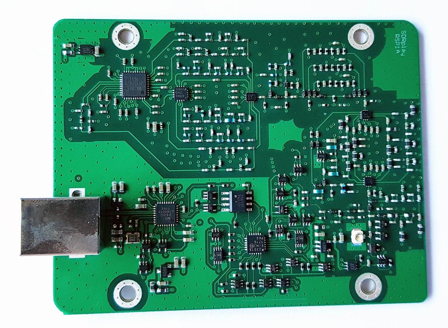
PCB Photos
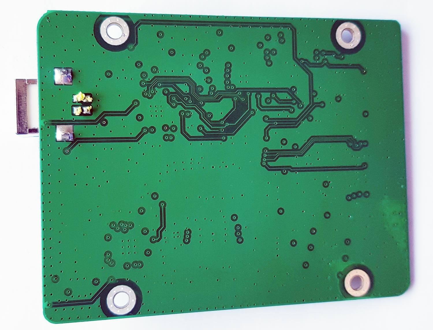
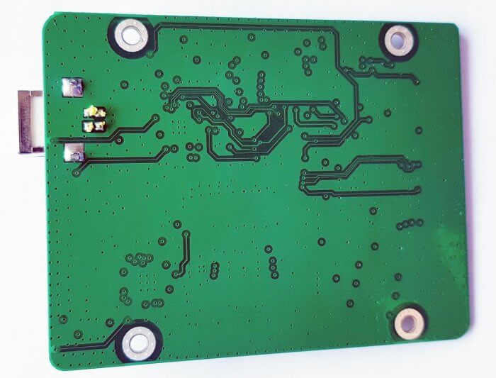
Compared to the RSP1 the RSP1A PCB is significantly more populated due to the additional filter banks.
Testing the RSP1A
Below we show some screenshots of tests that we made to compare the three RSP units. We focused on bands where the RSP1 or RSP2 had issues, and try to show how much improvement you can get from the RSP1A.
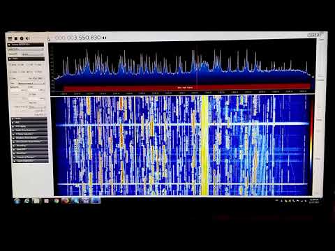
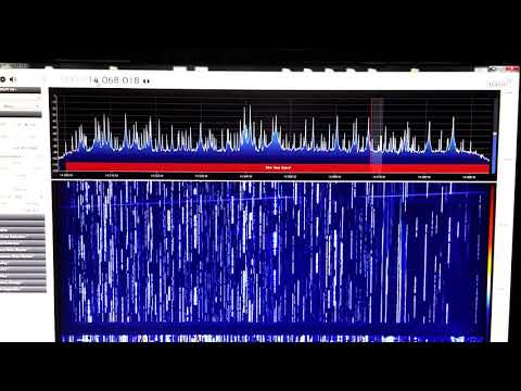
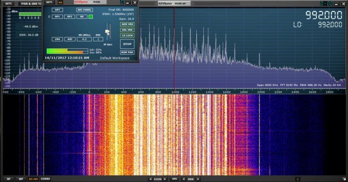
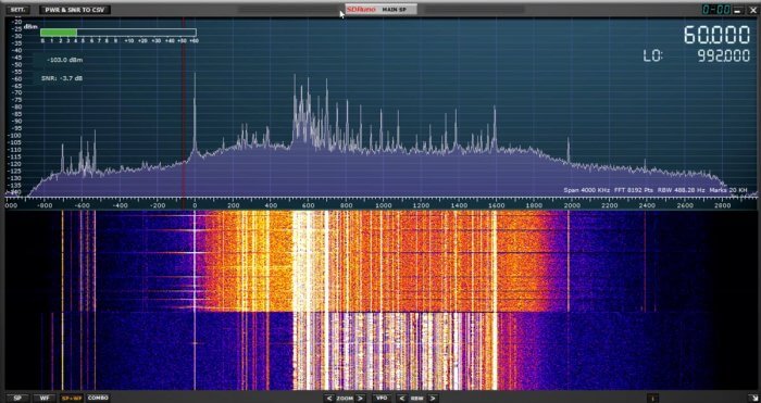
Medium Wave Broadcast AM Band
In the screenshots below we compare the three SDRs on the broadcast AM band which has some very strong signals. The RSP1 definitely shows signals of overloading and turning the gain down did not reduce the interference shown between 0 - 500 kHz.
The RSP1A on the other hand does not overload that easily. In the third screenshot we turn the MW notch on half way through the waterfall. The notch does not cover the entire AM band and signals at around 500 - 700 kHz are attenuated less. But turning it on does seem to do enough to solve most imaging problems as will be seen in the next tests.