Receiving the Bitcoin Blockchain from Satellites with an RTL-SDR
Bitcoin is the worlds first and most popular digital currency. It is steadily gaining in value and popularity and is already accepted in many online stores as a payment method. In order to use Bitcoin you first need to download a large database file called a ‘blockchain’, which is currently at about 152 GB in size (size data obtained here). The blockchain is essentially a public ledger of every single Bitcoin transaction that has ever been made. The Bitcoin software that you install initially downloads the entire blockchain and then constantly downloads updates to the blockchain, allowing you to see and receive new payments.
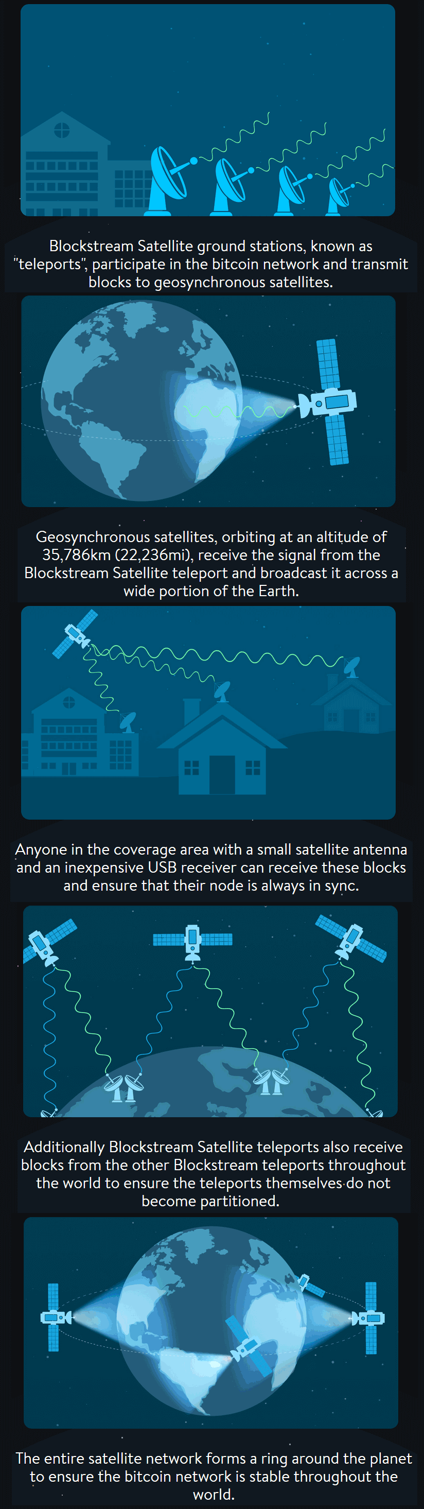
Blockstream is a digital currency technology innovator who have recently announced their “Blockstream satellite” service. The purpose of the satellite is to broadcast the Bitcoin blockchain to everyone in the world via satellite RF signals, so that even in areas without an internet connection the blockchain can be received. Also, one problem with Bitcoin is that in the course of a month the software can download over 8.7 GB of new blockchain data, and there is also the initial 152 GB download (although apparently at the moment only new blocks are transmitted). The satellite download service appears to be free, so people with heavily metered or slow connections (e.g. 3G mobile which is the most common internet connection in the third world/rural) can benefit from this service as well.
The service appears to be somewhat similar to the first iteration of the Outernet project in that data is broadcast down to earth from satellites and an R820T RTL-SDR is used to receive it. The blockstream satellite uses signals in the Ku band which is between 11.7 to 12.7 GHz. An LNB is required to bring those frequencies back down into a range receivable by the RTL-SDR, and a dish antenna is required as well. They recommend a dish size of at least 45 cm in diameter. The signal is broadcast from already existing satellites (like Outernet they are renting bandwidth on existing satellites) and already 2/3 of the earth is covered. The software is based on a GNU Radio program, and can be modified to support any SDR that is compatible with GNU Radio. They write that the whole setup should cost less that $100 USD to purchase and set up.
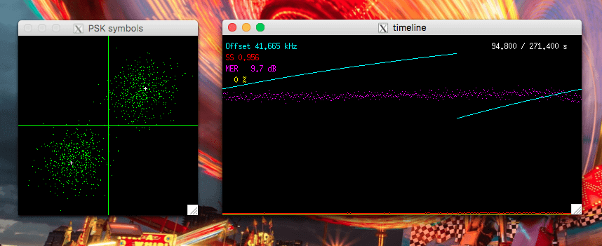
To set it up you just need to mount your satellite antenna and point it towards the satellite broadcasting the signal in your area, connect up your LNB and RTL-SDR and then run the software on your PC that has GNU Radio installed.
More details can be found on the Blockstream Satellite website, and technical details about the software and hardware required can be found on their GitHub page.
Some may wonder what’s the point if you can’t transmit to the service to make payments with it. Over on this Bitcoin Reddit thread user “ideit” explains why it’s still useful in this nice quote.
You sell goats in a small village. A customer wants to buy a goat, but you have no banks so people have put their money into bitcoin. Your customer goes to the village center which has a few computers hooked up to the internet. He sends you payment then comes to get his goat. You don’t have internet near your goat farm, but you’re connected to the satellite so you can see he sent you payment and you give him his goat.
Or, you live in an area that caps your bandwidth. You want to run a full node, but downloading blocks eats away at your cap. Connecting to a satellite reduces your bandwidth usage.
Or, you’re using an air gapped laptop to sign transactions from your wallet for security reasons. You can now connect that laptop to the satellites so your laptop can generate its own transactions without connecting to the internet.
Or, your internet connection is terrible. You can usually broadcast transactions since they’re small, but downloading blocks and staying in sync with the blockchain is literally impossible. Connect to a satellite and now it’s simple.


![[EN subs] ISS SSTV Event Juli 2017 - Empfang von drinnen und V-Dipole](https://www.rtl-sdr.com/wp-content/plugins/wp-youtube-lyte/lyteCache.php?origThumbUrl=https%3A%2F%2Fi.ytimg.com%2Fvi%2FSTmvu34O610%2F0.jpg)