FlightAware ProStick: A new ADS-B optimized RTL-SDR with built in LNA

The FlightAware team have today announced the release of the "ProStick", an RTL-SDR dongle that they write has been modified for improved ADS-B reception. The new FlightAware RTL-SDR's main defining feature is that it comes with a built in low noise amplifier (LNA) on the front end. The built in LNA is optimized for the ADS-B frequency of 1090 MHz and has 19 dB of gain with a 0.4 dB noise figure and an OIP3 of +39dB. They claim that the new unit will give a 20-100% performance boost in terms of range for Mode S reception when compared to a standard RTL-SDR.

As the increased gain and amplifier non-linearities can cause overload and intermodulation to more easily occur, the FlightAware team stresses that you must use the new device with a 1090 MHz filter, such as their FlightAware filter. In a previous post we reviewed the FlightAware filter and antenna and found that they performed very well and are great value for money.

The new unit is priced cheaply at $16.95 + shipping on Amazon for US buyers, and $24.95 + shipping on eBay for international buyers.

So far we haven't seen any circuit photos or news about which LNA chip has been used, but we intend buy a unit and do a review when it arrives.

One criticism about this unit that we can already see is that it should be understood that good RF design teaches us to always place the LNA as close to the antenna as possible to overcome cable loss and keep the noise figure low. Placing the LNA at the antenna vs at the receiver makes a huge difference in performance, depending on how long and lossy your coax cable run is. Furthermore, integrating an LNA into the receiver ruins the system for optimal performance with an LNA placed by the antenna due to the reduced linearity caused by the additional internal LNA. The post at http://ava.upuaut.net/?p=836 explains optimal LNA placement very well. We think that perhaps selling an external LNA and bias tee module would have been a significantly better idea to optimize ADS-B reception. However, the additional LNA should help to reduce the noise figure of the dongle by a few dBs which will result in improved ADS-B reception as long as signal saturation does not occur. 
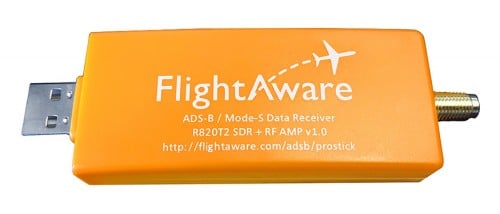
The new FlightAware ADS-B optimized RTL-SDR.
The new FlightAware dongle running on a PiAware Raspberry Pi system.
The new FlightAware dongle running on a PiAware Raspberry Pi system (actual unit uses SMA).

Meteor M-N2 now active again

According to various reports the Russian Meteor M-N2 satellite appears to be active again once more. The Meteor M N-2 is a polar orbiting Russian weather satellite that was launched in July 2014. It transmits with the LRPT protocol which allows us to receive weather satellite images with an RTL-SDR that are of a much higher resolution than the NOAA APT satellites. 

Unfortunately late last year Meteor M N-2 had some problems and LRPT transmissions were turned off for the time being. During this downtime the Russian space agency switched the LRPT transmitter on the older Meteor M N-1 satellite back on, even though the satellite was tumbling in orbit. Currently people are not reporting any signal from Meteor M N-1, so this may have been turned off, perhaps temporarily.

Now however, it seems that Meteor M N-2 has been switched back on again and various people have already successfully received its signal. If you want to receive these Meteor M N-2 weather images with an RTL-SDR dongle or other SDR then you can view the tutorial written by Happysat here.

Another Sample LRPT Image
A Sample LRPT Image from Meteor M N-2

Michael Ossmann’s Talk on RF Circuit Design

At the 2015 Hackaday super conference Michael Ossmann (designer of the HackRF SDR and various other RF products) gave a talk called “Simple RF Circuit Design”. His talk explains in very simple terms how to successfully create RF circuits without the need to do any complicated calculations. The workshop blurb reads:

This workshop on Simple RF Circuit Design was presented by Michael Ossmann at the 2015 Hackaday Superconference. It sold out almost immediately and for good reason. He has designed numerous popular tools like the the HackRF One and YARD Stick One. Michael’s depth of knowledge and experience make him a leader in a field that is often called a dark art. There is no reason to fear RF design. Follow his recommendations and remove some of the mystery from the topic.

Essentially his talk boils down to 5 rules:

  1. Use Four Layers
    You’ll have less RF trouble and design work with four layers than on a two layer board. Four layers allows you to have unbroken power planes which helps to reduce ground loops.
  2. Use the Most Integrated Component Possible
    Instead of designing your own RLC circuits and filters and taking into account various factors like Q values, just use an integrated circuited with defined parameters. 
  3. Design for 50 ohms Everywhere
    Keep every thing matched to the standard 50 Ohms for optimal impedance matching.
  4. Follow Manufacturer Recommendations
    Use the layouts specified by the manufacturer.
  5. Route the RF Parts First
    Route the most critical part, the RF section first and keep digital lines away.
Michael Ossmann: Simple RF Circuit Design

Building a 28.8 MHz TCXO for the RTL-SDR

For accurate frequency tuning even amongst large temperature in an SDR, a Temperature Compensated Crystal Oscillator (TCXO) should be used as the main oscillator. Standard RTL-SDR dongles used a frequency of 28.8 MHz and do not come with a TCXO, but for some time now we have been selling our own branded dongles that come with a TCXO built in (out of stock at the moment sorry – back in the first half of April!). If you have an older or other dongle that does not have a TCXO it can be an interesting exercise to hack one in yourself. The biggest problem though, is that 28.8MHz TCXO oscillators are not commonly found for sale in low quantities.

Over on YouTube user devttys0 (Craig) has uploaded a video that thoroughly explains the theory behind creating a home brew 28.8 MHz TCXO out of a standard non-temperature controlled 19.2 MHz oscillator. The build involves halving the frequency, and then filtering and using the third harmonic as the clock signal (19.2/2 * 3 = 28.8 MHz), as well as creating the temperature compensation circuitry.

On his blog Craig has also uploaded schematics and a frequency temperature curve he measured from his home brew TCXO.

If you wanted to make something a little easier to build then we recommend looking at our previous post which shows how an experimenter used an SI5351A voltage controlled oscillator on the RTL-SDR.

A GNU Radio Based ISDB-T and RTL-SDR Compatible 1Seg Decoder

In most parts of the world the DVB-T standard is used to air digital HDTV. In the USA the ATSC standard is used, and in China DTMB is used instead. In other countries such as Brazil, Peru, Argentina, Chile, Honduras, Venezuela, Ecuador, Costa Rica, Paraguay, Philippines, Bolivia, Nicaragua and Uruguay a third standard called “ISDB-T International” is used which is based on the Japanese ISDB-T standard. 

Digital broadcast standards used in each country.

Recently a team from Uruguay has been working on creating a ISDB-T receiver in GNU Radio. With this decoder ISDB-T signals can be received with a wide bandwidth SDR (needs to be 6MHz or larger) and then decoded into a video file. Because ISDB-T is so similar to DVB-T they have based much of their code on gr-dvbt which is a GNU Radio based DVB-T decoder.

In addition to the ISDB-T decoder, they have also implemented a 1-seg decoder. 1-seg is a mobile HDTV service that exists in Japan, Argentina, Brazil, Chile, Uruguay and Peru. It runs on the ISDB-T system, and is called “1-seg” because it’s data occupies 1-segment of the 13-segment based ISDB-T bandwidth. It is used in small mobile TV receivers, many of which are now built directly into mobile phones sold in countries that use ISDB-T. Due to it’s much lower bandwidth requirement the 1-seg decoder can be used with an RTL-SDR dongle, and has already been tested to work.

A typical 1-seg capable Japanese mobile phone receiving digital mobile TV.
A typical 1-seg capable Japanese mobile phone receiving digital mobile TV. With the GNU Radio 1-seg decoder these transmissions can be received with an RTL-SDR.

ADS-B Decoder for the SDRplay RSP Now Available

A new ADS-B decoder for the SDRplay RSP has recently been released by the SDRplay programmers. The SDRplay is a $149 USD software defined radio with a 0.1 – 2000 MHz range, 12-bit ADC and up to 8 MHz of bandwidth. In a previous review we compared it against the Airspy and HackRF.

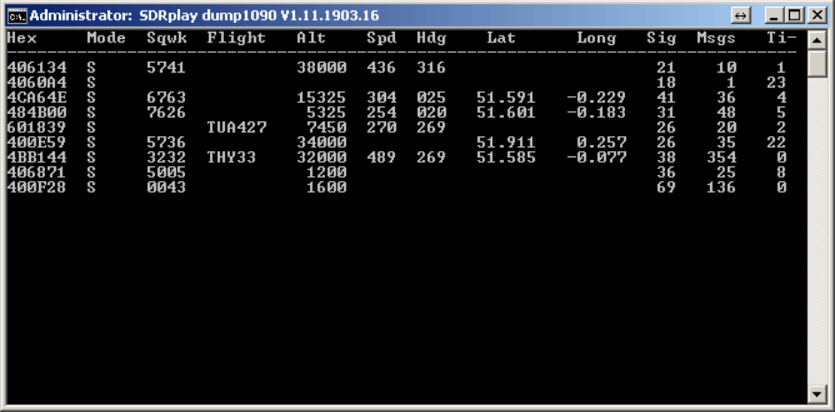
The SDRplay team have based their new decoder on the multi-platform compatible dump1090 code, which is an ADS-B decoder that was originally written for the RTL-SDR. The Windows version can be be downloaded from http://www.sdrplay.com/windows.html, and the code for other platforms can be downloaded from https://github.com/SDRplay.

To help with the installation procedure the SDRplay has also provided a manual (pdf) which shows exactly how to download and set up the required ADS-B software on a Windows system. They also write that the software is fairly new and is still being optimized for best performance.

In the future after the software is further optimized we hope to compare the RSP against the RTL-SDR and Airspy on ADS-B reception.

The SDRplay compatible version of dump1090 deceiving ADS-B data.

Inspectrum: A New Tool for Analysing Captured Signals

Inspectrum is a Linux and OSX based tool that can be used for analysing captured signals. It is compatible with the IQ files generated from SDRs, such as the RTL-SDR or HackRF.

Over on YouTube user Mike has uploaded a video that demo’s the latest version of Inspectrum. He shows how the tool can be used to quickly browse the waveforms in a captured signal and how it can be used to determine various digital binary signal properties through an overlay that can be dragged to match the bit frequency of the captured signal.

This program looks like it is shaping up to be a very useful tool for those interested in reverse engineering digital signals. The Inspectrum code and installation procedure can be found at https://github.com/miek/inspectrum.

inspectrum tuner demo

KiwiSDR: 30 MHz Bandwidth VLF to HF SDR now on KickStarter

Back on February 8 we posted about the up and coming KiwiSDR, a software defined radio with 30 MHz of bandwidth and a tuning range that covers 0 – 30 MHz (VLF to HF). It is intended to be a low cost web based SDR that can be accessed from all over the world via a browser interface. 

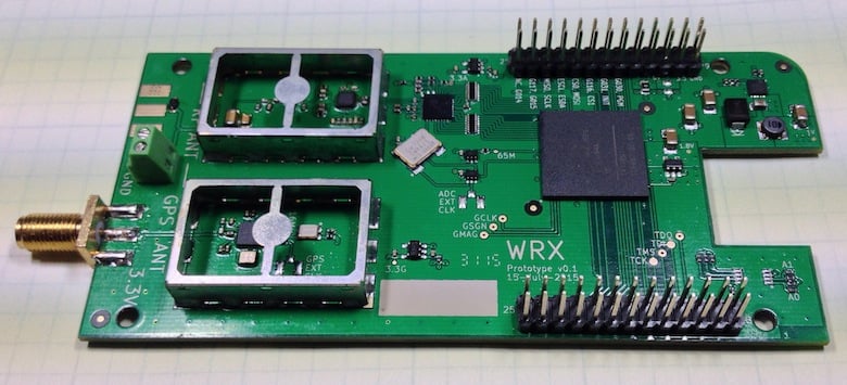
The KiwiSDR is designed as a cape for the BeagleBone Black mini embedded computer, and uses a LTC 14-bit 65 MHz ADC and Xilinx Artix-7 A35 FPGA. It also has an integrated SDR based GPS receiver which is used to automatically compensate for any frequency drift from the main 66.6 MHz oscillator. It runs on the OpenwebRX web based software, which many RTL-SDR users have already been using to stream live radio to the web.

Today the KiwiSDR started its crowd funding campaign on Kickstarter. A full KiwiSDR can be purchased for $199 USD, or for $299 including an enclosure, BeagleBone computer and GPS antenna. The fundraising goal is for $50,000 USD and if successful they estimate delivery in October 2016. The creators of the KiwiSDR write:

Sure, the world doesn’t really need another SDR. But we haven’t found one with this set of features. In cost and performance, KiwiSDR fits between RTL-SDR USB dongle-style, or fixed DDC chip devices ($20 – $400, 8-12 bit ADC, limited bandwidth), and full 16-bit SDRs ($700 – $3500) while offering better wide-band, web-enabled capabilities than the more expensive SDRs.

Our main motivation is to enable new applications which utilize a significant number of programmable, web-accessible SDRs world-wide. Direction finding remains one of the great under-solved problems of shortwave listening, particularly for utility stations. Given the GPS timing available on the KiwiSDR, could time-of-arrival techniques between cooperating SDRs be used? We’d sure like to find out.

Also, we’d like to see data decoders built directly into the web interface of KiwiSDR. There are many standalone programs that demodulate and decode data signals from SDRs. But these are computer- and OS-specific and often require a complicated interface to the data stream from the SDR. For example, we have a prototype of a WSPR decoder that is integrated into the KiwiSDR interface.

There are currently three KiwiSDR servers running publicly at the moment, and they can be accessed at:

http://kiwisdr.sk3w.se:8073
http://kiwisdr.ece.uvic.ca:8073
http://kiwisdr.com:8073

The KiwiSDR Prototype
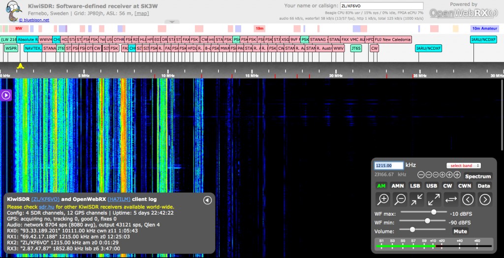
KiwiSDR Running on OpenWebRX. Full 0 - 30 MHz spectrum.
KiwiSDR Running on OpenWebRX. Full 0 – 30 MHz spectrum.