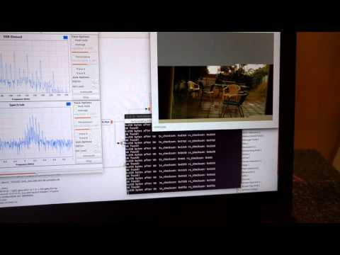
David and Mark are building a 115 kbit/s FSK SSDV (slow scan digital video) data system for high altitude balloons. In their system, on the balloon transmit side they use a Raspberry Pi, Raspberry Pi camera and a RFM22B wireless transceiver modulator board to transmit the SSDV FSK signal. On the receive side they use an RTL-SDR dongle, low noise preamplifier and a GNU Radio program to demodulate the SSDV images. The first video below demonstrates the hardware and GNU Radio program and shows them receiving the SSDV signal. In the second video they demonstrate that the images can be received at low signal levels (-106dBm) as well, by heavily attenuating the signal.
While testing the RTL-SDR for use in this system they also measured the noise figure of an R820T RTL-SDR dongle. The noise figure at maximum gain comes out at around 5.6 dB. By adding a low noise amplifier they reduce the measured noise figure down to 2 dB.
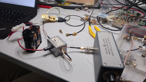
Testing the attenuated SSDV signal reception with an RTL-SDR.
In order to optimally receive NOAA weather satellite images a special satellite antenna tuned for 137 MHz should to be built. Generally either a QFH or turnstile antenna is recommended as these receive signals coming from the sky very well. If you are interested in receiving weather satellite images from NOAA satellites with an RTL-SDR dongle then we have a tutorial available here.
While QFH and turnstile antennas are not difficult or expensive to build, they still do require a small amount of electrical and construction skills. Over on YouTube user Wanderlinse shows us a possible alternative NOAA antenna that is simply made out of an old umbrella (the video is narrated in German, but it is easy to understand from the visuals). He uses a short BNC cable with crocodile clips, and connects one clip to the spines of the umbrella, and the other to the central metal shaft. For some reason this seems to create a good antenna that receives NOAA APT signals very well. To prevent wind issues he also cuts out some holes in the umbrella fabric.
Wanderlinse also shows that he can receive other signals with this umbrella antenna too, such as long wave, medium wave, shortwave, aircraft radio and ham radio.
Regenschirm Antenne NOAA APT Umbrella Antenna (quick n dirty)
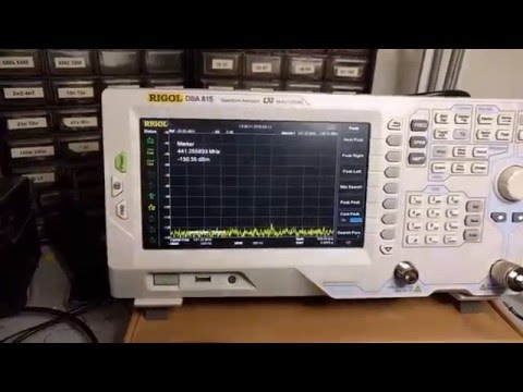
If you were to try to simply spot a GPS signal at 1.575 GHz in the spectrum on a waterfall in a program like SDR# you would probably fail to see anything. This is because GPS signals are very weak, and operate below the thermal noise floor. Only through clever processing algorithms can the actual signal be recovered.
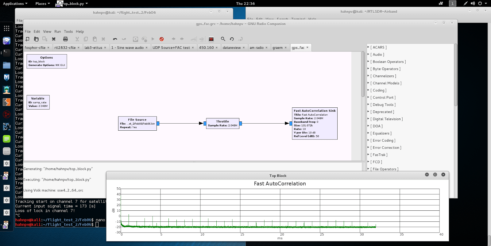
With real data passed through the fast autocorrelation block he is able to observe GPS signal peaks that occur every millisecond. E.p. explains the reason for this:
Why every millisecond? The coarse/acquisition code for GPS (C/A) has a period of 1023 chips which are transmitted at a rate of 1.023 MBit/s. This results in period of 1 millisecond. BAM!
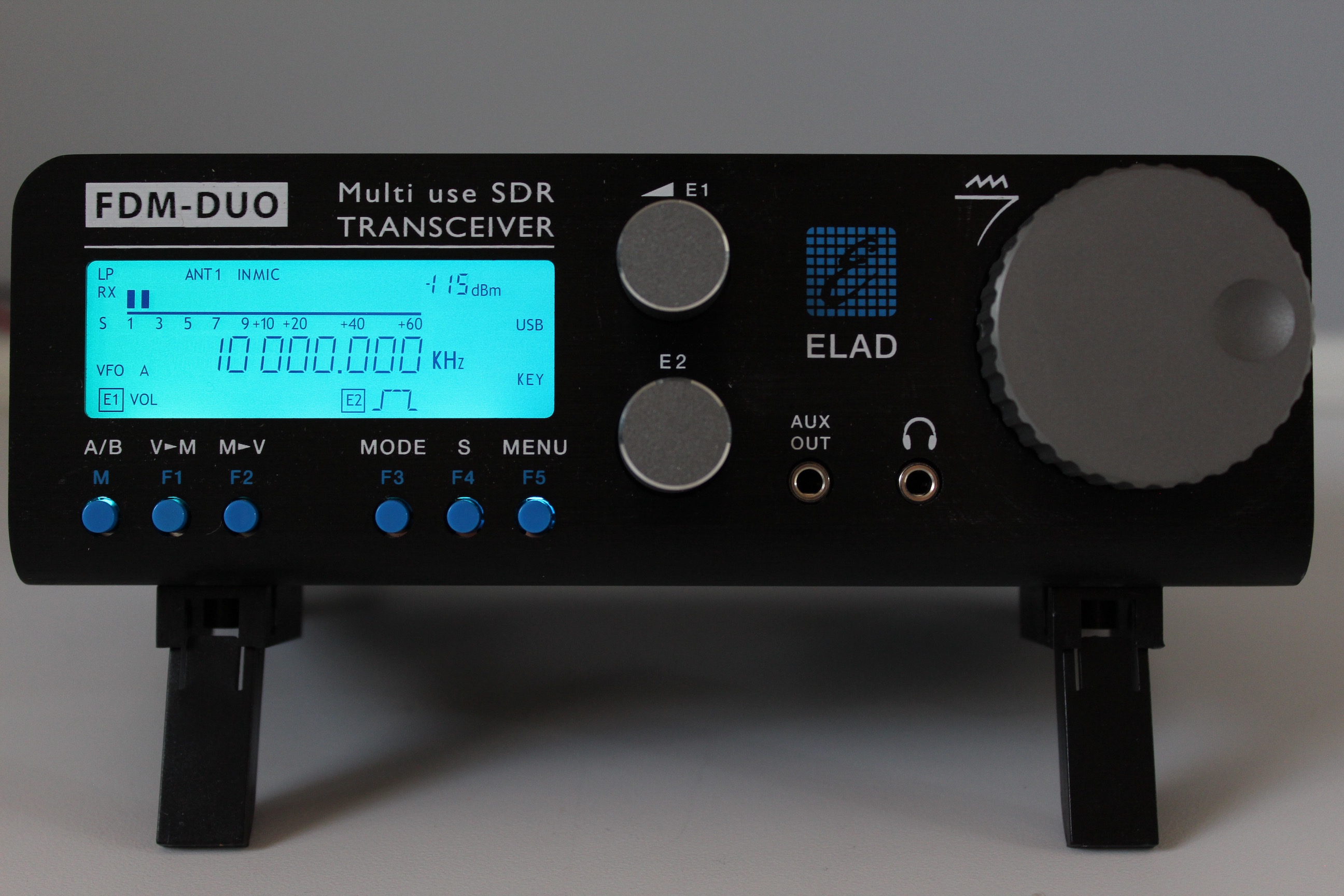
The Elad FDM-DUO is a high end $1149 USD Italian made software defined radio transceiver (transmit and receiver) with a frequency range of 10 kHz – 54 MHz, a 16-bit ADC, a bandwidth of up to 6 MHz and can transmit with up to 5 – 8 watts. It is a product targeted at ham radio enthusiasts who want a gradual transition into software defined radios. It can work in two modes: either as a standalone computer-less radio just like a regular hardware radio, or as a fully functional computer based SDR.
The Italian made FDM-DUO has to be the most versatile, well designed, and well thought out SDR system currently on the market.
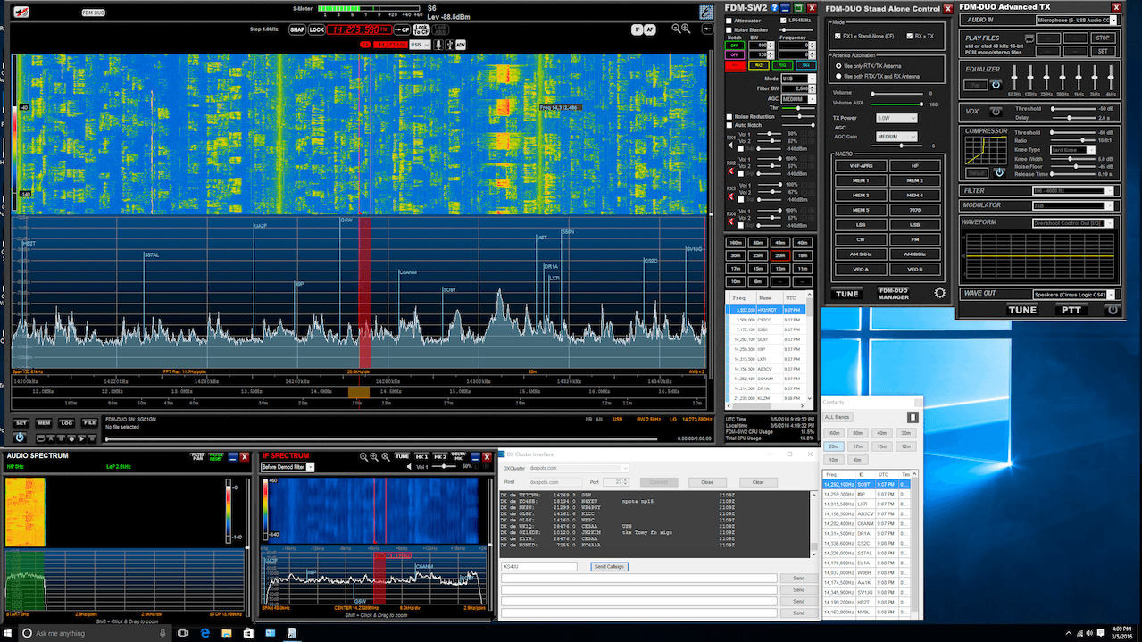
The review by hamradioscience goes over several points such as explaining what all the connectors on the radio are for, reviewing the ergonomics, reviewing the radio in standalone mode and in PC based SDR mode and he also reviews the companion software package. The reviewer is especially impressed with the included software, basically making the point that this system is a full SDR transceiver package (all you need in terms of hardware AND software).
Generally we recommend more general purpose and lower cost wideband VHF/UHF SDR’s like the Airspy, SDRplay RSP or HackRF (see our review on those SDRs here), but if you are not limited by budget and want to use an SDR mostly for HF amateur radio purposes then the Elad FDM-DUO looks like a winner. The author concludes with the following comment.
Elad got so many things right with the FDM-DUO that it is hard find much to criticize. Unlike so many SDR systems available today, the FDM-DUO SDR system feels like less of a “science project” and more of a finished consumer product. For those who wants a SDR radio system that “just works” and easy to use, the FDM-DUO is a great choice. Also, kudos to Elad for providing such a well done SDR program. The program was very stable over the review period. No, crashing at just the wrong time say during a contest. Heck even if it did, it wouldn’t matter much since you could just continue on using the FDM-DUO as a standalone rig. With some of the larger radio manufacturers dipping their toes in the SDR area, they should take note of what Elad has done with the FDM-DUO. Elad has truly created a very flexible multi-use system with the FDM-DUO and a darn fine SDR radio system at a very good value.
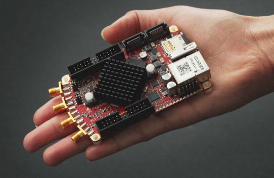
The Red Pitaya is a type of advanced digital acquisition device (DAQ) that is marketed mainly for use as a type of digital oscilloscope. But it has an on board programmable FPGA and through various downloadable apps can be used for many different applications, such as a spectrum analyzer, impedance analyzer, bode plotter, signal generator or even as a software defined radio.
Back in February we posted how Pavel Demin had created an SDR app for the Red Pitaya which allows it to be used with common SDR software such as SDR# and HDSDR. The Red Pitaya has an on board 14-bit ADC which when in SDR mode can receive signals from between 0 to 50 MHz with a bandwidth of up to 2.5 MHz.
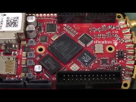
Recently, Dave from the hugely popular electronics YouTube show EEVBlog reviewed the Red Pitaya. Whilst Dave doesn’t try out the SDR apps, he tests it out as an oscilloscope and also tests more of its default apps such as the spectrum analyzer.
Unfortunately in his review the Red Pitaya does not seem to live up to expectations. During operation Dave encounters problems with the WiFi connectivity, frequent problems with the web based apps crashing and freezing on him, and discovers that the provided apps are extremely rudimentary and provide very little functionality. He mentions that the device is probably more useful for people wanting to write their own customs apps for specific applications, but as an out of the box digital measurement tool it is not there yet.
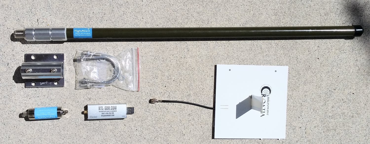
In this post we will review the FlightAware ADS-B Antenna and their 1090 MHz band pass filter. The FlightAware ADS-B antenna is claimed to have 5.5 dBi of gain, a rugged weatherproof radome and N-type female connector. It costs $44.95 USD on Amazon for US customers and $54.95 USD on eBay for international customers (plus shipping). They write that they are selling this antenna at cost in order to improve FlightAware coverage.
The FlightAware ADS-B filter is a bandpass filter with a pass range of 980MHz - 1150MHz, ~1.5dB insertion loss and more than 40dB attenuation of unwanted frequencies. It costs $19.95 USD on Amazon for US customers and $24.99 USD on eBay for international customers (plus shipping). Generally it is much cheaper than other ADS-B filter options on the market.
FlightAware.com is a company that specializes in aggregating ADS-B data from contributors around the world. People can contribute by using the FlightAware official hardware, or with a simple SDR, like an RTL-SDR dongle. They display the data on their website as it can be used to help track flight arrival times. A similar company is flightradar24.com.
If you are interested in getting started with ADS-B reception with your RTL-SDR then we have a tutorial here.
FlightAware ADS-B Antenna
The FlightAware antenna is about 64cm in length and about 2cm in diameter. It uses an N female connector and comes included with mounting brackets and U-bolts. It is painted olive green.
In the photo below we compare the size of the antenna against a reference monopole antenna, an RTL-SDR dongle and the FlightAware ADS-B filter. The antenna appears to be very solidly built and of a high quality finish. The antenna is wareproofed with some silicon caulking used around the seams of the endcaps.
Size comparison
The FlightAware ADS-B antenna is a collinear type antenna. Collinear antennas are omnidirectional (receives equally from all directions) and have a higher gain compared to most other omnidirectional antennas, but their radiation pattern is flattened and directed more towards the horizon. This is a good thing for receiving planes that are far away as they will be at lower elevations, but aircraft at higher elevations relative to your antenna may be received poorer. Although, it is likely that any aircraft at high elevations to your position will be closer to you anyway, and thus have a stronger signal making the reduced gain at higher elevations less important. Judging by it's ~60cm length and it's specified gain of 5.5dBi, the FlightAware antenna is likely to be a 4 element collinear.
A 4 element collinear generally has positive gain from 0 - 20 degrees of elevation, whereas a simple dipole or ground plane may have positive gain from between 0 - 40 degrees of elevation. A typical commercial jet flys at about 10km. At a distance of 100km this jet would be at a 5.7 degree elevation, and at 10km 45 degrees. Smaller aircraft fly at about 3km maximum, and at 100km would have an elevation of 1.7 degrees, and at 10km 16.7 degrees, so the collinear covers most cases.
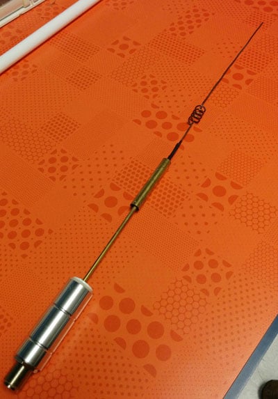
A reader wrote in to us to let us know that the internals of the FlightAware antenna had actually previously been posted in an old thread on their forums. From the image it looks like the antenna may be a sleeved dipole + whip + impedance matching design, or something similar. This design is somewhat of a collinear design thanks to the additional whip which also gives a flatter radiation pattern with more gain direction out towards the horizon. These antennas are omnidirectional (they receive equally from all directions) and have a higher gain compared to most other omnidirectional antennas, but their radiation pattern is flattened and directed more towards the horizon. This is a good thing for receiving planes that are far away as they will be at lower elevations, but aircraft at higher elevations relative to your antenna may be received poorer. Although, it is likely that any aircraft at high elevations to your position will be closer to you anyway, and thus have a stronger signal making the reduced gain at higher elevations less important.
The internals of the FlightAware antenna.
If you live in a valley, or have multiple obstacles such as trees or buildings blocking your view of the horizon then the higher gain design may work worse than a dipole/quarter wave ground plane/folded monopole type antenna. In this situation you'd mainly only be able to receive ADS-B signals from higher elevations, so an antenna with a less flat radiation pattern would work better. See the end of this post for some example radiation pattern diagrams.
Luke uses his own Trunk Recorder software and writes that he has modified it to support multiple SDR’s. His software has the following description:
Trunk Recorder is able to record the calls on a trunked radio system. It uses 1 or more Software Defined Radios (SDRs) to do. The SDRs capture large swatches of RF and then use software to process what was recieved. GNURadio is used to do this processing and provides lots of convienent RF blocks that can be pieced together to do complex RF processing. Right now it can only record one Trunked System at a time.
Trunk Recorder currently supports the following:
P25 & SmartNet Trunking Systems
SDRs that use the OsmoSDR source ( HackRF, RTL – TV Dongles, BladeRF, and more)
Ettus USRP
P25 Phase 1 & Analog voice
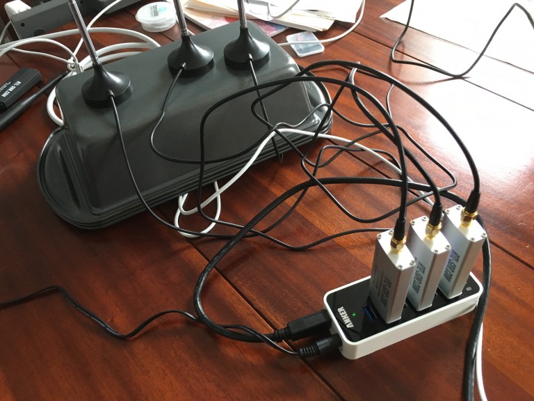
Luke also mentions that using three RTL-SDRs like this seems to be more efficient on the CPU than using a single SDR that has 8 MHz of bandwidth due to the amount of down sampling that needs to be done on larger bandwidth SDRs.
When I was using a single SDR, each Recorder had to take in the full 8MHz and pull out the small 12.5KHz that was interesting. The end results is that I could only record about 3 channels at once before the CPU got overloaded. Since that control channel was going at the same time, that was the equivalent of about 32MHz of bandwidth to process.
With the RTL-SDR, each Recorder only has to look at 2MHz, which puts a lot lighter load on the CPU. Roughly speaking, having 3 Recorders active, plus the control channel would mean that only a total of 8MHz was being processed. As you can see, this means that it scales much more efficiently.
Using three RTL-SDR’s to monitor a 6 MHz trunking system.
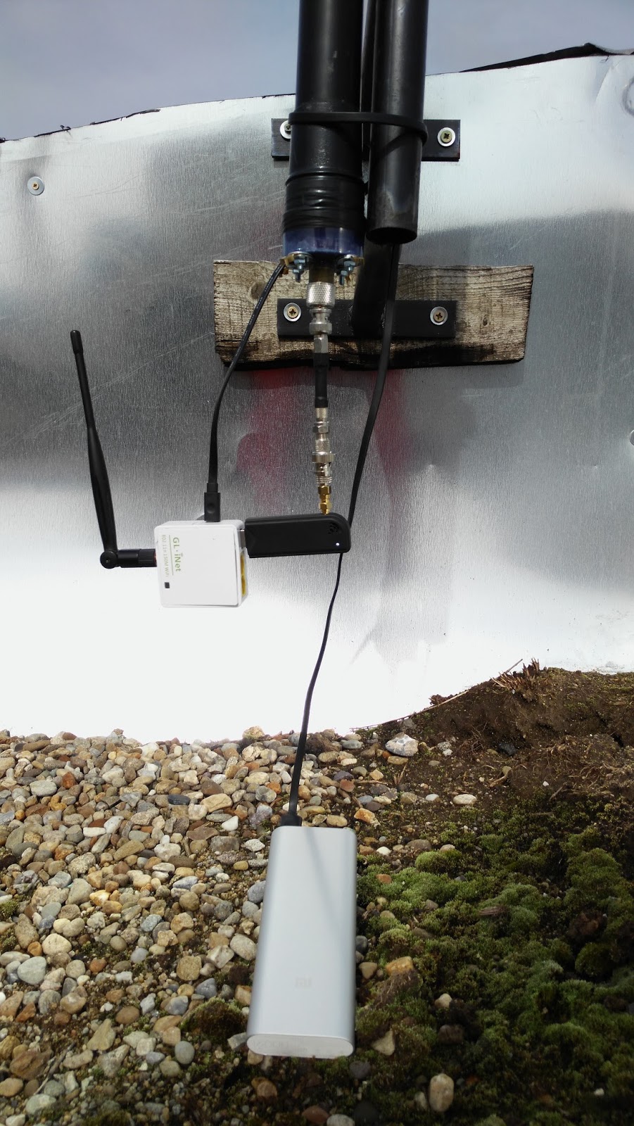
With an RTL-SDR connected and the router running rtl_tcp, the router can be placed anywhere there is power (yo2ldk uses a portable battery pack) to create a remote radio receiver with absolutely no coax cable losses. It’s WiFi range could be extended over long distances by using a directional Yagi antenna.
Using routers instead of mini computers like the recently released Raspberry Pi 3 may be a good option because they are very small, usually much cheaper, maybe be more power efficient, and may work better at transmitting the large amounts of data rtl_tcp requires.
In the future yo2ldk hopes to install everything into a shielded metal case, add an upconverter and also a solar panel for remote power.
YO2LDK’s remote RTL-SDR set up.
We note that if you have an old Android phone, then this could also potentially be used as a remote RTL-SDR server. To create an android RTL-SDR server simply download the Martin Marinov Android RTL2832U Driver from the Google play store. Find the IP address of your Android phone by going to Settings -> About Device -> Status -> IP Address. Then open the RTL2832U driver app and click on “Enable advanced mode (for debug & stream to PC)”. Initially the rtl_tcp string will have the code “-a 0.0.0.0”, simply change this to the IP address of your Android phone, for example “-a 192.168.1.15” and then click Start stream. Now on a remote PC connected to the same network open SDR# go to RTL-SDR (TCP) and type in the IP address of the phone and use the port number 14423. Click the play button and you should now be streaming your RTL-SDR data over WiFi.