Januaries review discusses the Airspy specifications, the unboxing, ease of use and reception results. The review is generally positive and he writes that in the coming weeks he hopes to do some comparisons between the RTL-SDR and Airspy.
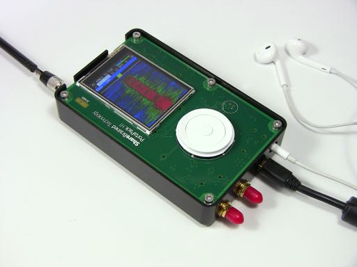
The HackRF PortaPack is a portable LCD screen with control interface and processor that connects to a HackRF software defined radio. The PortaPack’s goal is to allow for portable RF spectrum visualization, tuning and eventually demodulation of many modes. It has been in development from around the time of the August 2013 HackRF kickstarter and is now almost ready to be shipped out to the initial backers. For more information about the PortaPack see this Hak5 segment that we previously posted about where Jared Boone the inventor of the PortaPack is interviewed.
In his post Jared writes:
Getting the PortaPack H1 ready for shipping was a long slog. And as is my way, I took a lot of detours along the way. I incorporated a lightweight operating system (ChibiOS) into the firmware. I built a simple UI framework that would support arrow-key navigation, with touch as an option where appropriate. I developed a sophisticated test jig (based on this) to ensure the units I ship work correctly. I designed a milled aluminum case that I’ll offer as an option. And I finished and tested all the units myself, including doing failure analysis on a bunch of PortaPacks. I learned a great deal, and hope that my next product development cycle will be much easier and faster.
Because of all the manufacturing effort, work on the firmware hasn’t advanced very far. At this point, the PortaPack is mostly useful as a basic narrowband AM/FM receiver. But there’s still a lot of capability to be tapped in the HackRF ARM processors! I’m eager to get back to firmware, and implement more signal analysis and capture functionality, along with some digital modes demodulation and decoding support.
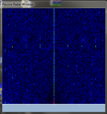
The first one is Passive Radar which bases on the signal from only one dongle. The ambiguity function is the same as in advanced projects with the difference that I implemented self-correlate function instead of cross-correlate one which is used in 2 dongles projects. Such solution theoretically should works as can be found in internet. It should be noticed that for proper work of such passive radar the direct signal should be comparable in strength to the reflected one. This plugin is still under development.
In the future he hopes to be able to support two dongle passive radar as well.
The Passive Radar plugin by Dr. Kaminski in SDR#.The Passive Radar window.
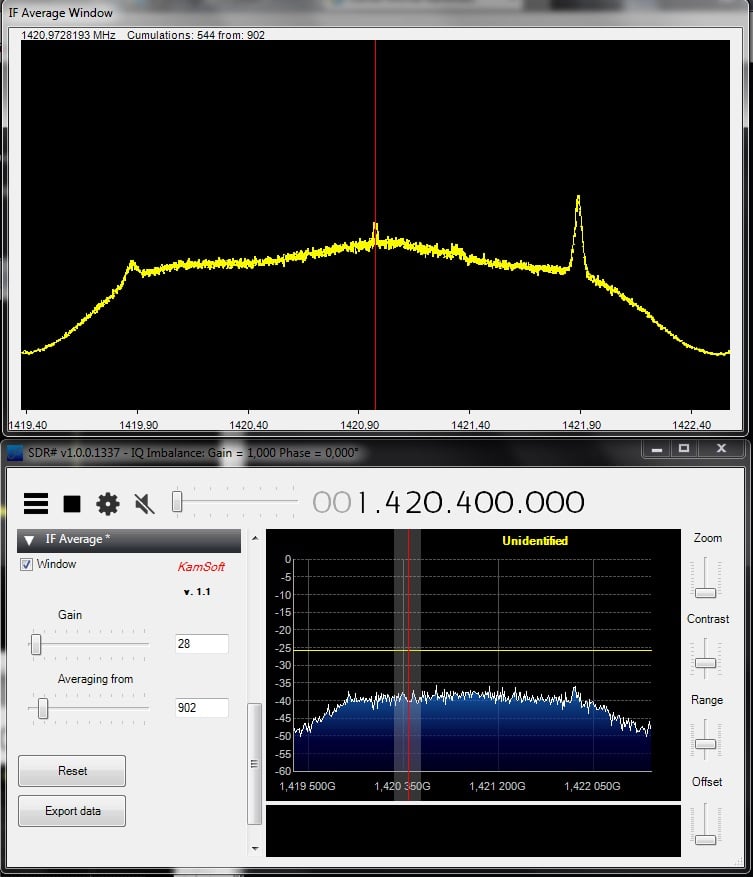
The second plugin is called "IF Average". This plugin allows the IF signal (the entire active bandwidth is what he seems to be referring to) to be averaged which is useful for many applications including radio astronomy projects such as detecting the Hydrogen line. He writes:
The second plugin which is finished is for IF signal averaging. It is important in case of radio-astronomical observations. It allows to cumulate signals (up to 10000 samples in real time), present them in friendly way and save for further work.
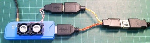
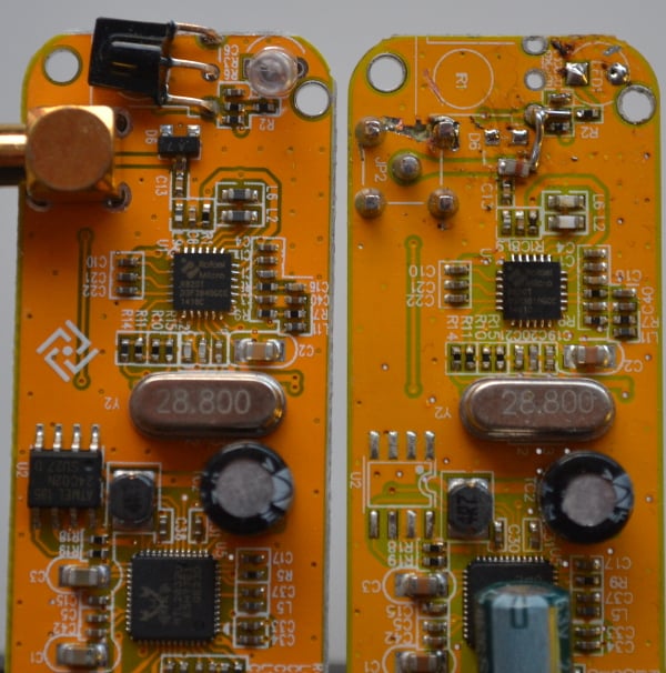
From his measurements, Nobu found that the internal temperature of the RTL-SDR can reach up to 70 degrees Celsius. So in order to cool the RTL-SDR Nobu has tried two methods. One involving using small cooling fans, and the other involving adding heat sinks to all heat producing components. It seems from the translation that he writes that the improved heat dissipation has extended his ADS-B reception slightly.
Recently RTL-SDR.com reader Dr. Phil wrote in to let us know about some PDF notes that he has created about the RTL-SDR dongle. There is some good information in his documents and the notes mainly focus on using the RTL-SDR with the direct sampling mod to receive HF.
His other documents also explain concepts such as imaging, interference and gain, how to reduce interference, input impedance of the Q sampling pads, intermediate frequency, and sample rate. In addition he has also uploaded some documents where he has calculated for various AM, FM and SW stations at what frequencies images will show up. His final document also discusses the Mirics SDR chipsets which are used in the SDRPlay.
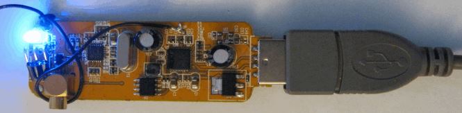
Over on his blog Elias has uploaded a post that shows how he modified his RTL-SDR dongle to provide remote DC power through a bias tee. A bias tee allows you to inject DC voltage into the coax cable to power active antennas, or devices that need to be near the antenna such as LNA’s. The bias tee prevents DC power from entering the RTL-SDR front end (which would fry it) via a blocking capacitor, and also prevents RF energy leaking into the power supply by using a blocking inductor.
In his post he writes how he made a simple hardware hack to the RTL-SDR PCB to enable 3.3V from the USB power supply to be used to power his active GPS antenna. To do this he removes the static protection diode and connects a nearby 3.3V pad to the antenna output through an inductor. The RTL-SDR already has a DC blocking capacitor in place.
He writes that this mod unfortunately requires the static protection diode to be removed, so the RTL-SDR is no longer protected from static discharge.
Back in July of last year we posted about a video from oh2ftg where he showed how he was able to get his RTL-SDR to act as a crude transmitter by using the RTL-SDR’s leaky oscillator.
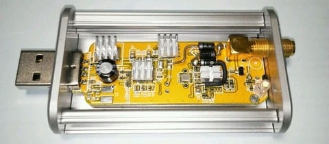
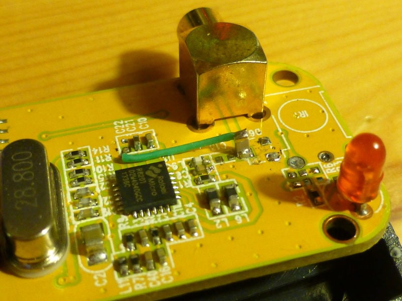
Oscar decided to take a standard RTL-SDR dongle and modify it so that it outputs a signal from the mixer output of the R820T tuner chip. To do this he removes some unneeded components from the PCB, and wires pin 5 of the R820T to the MCX antenna port through a 100pF capacitor. Pin 5 is connected to the mixer output from inside the R820T chip.
TX mod for the RTL-SDR.
After performing the hack the RTL-SDR is able to output a signal anywhere between 500 MHz to 1500 MHz 1.8 GHz to 3 GHz (see why). To control the output frequency you simply need to tune to the frequency you want to transmit at in SDR# (after setting an offset to account for the R820T’s IF offset). This tunes the mixer in the R820T and causes the output frequency to change.
In the future Oscar hopes to take this idea further by creating a specific tuning application for the generator and finding a way to possibly FM modulate the output.
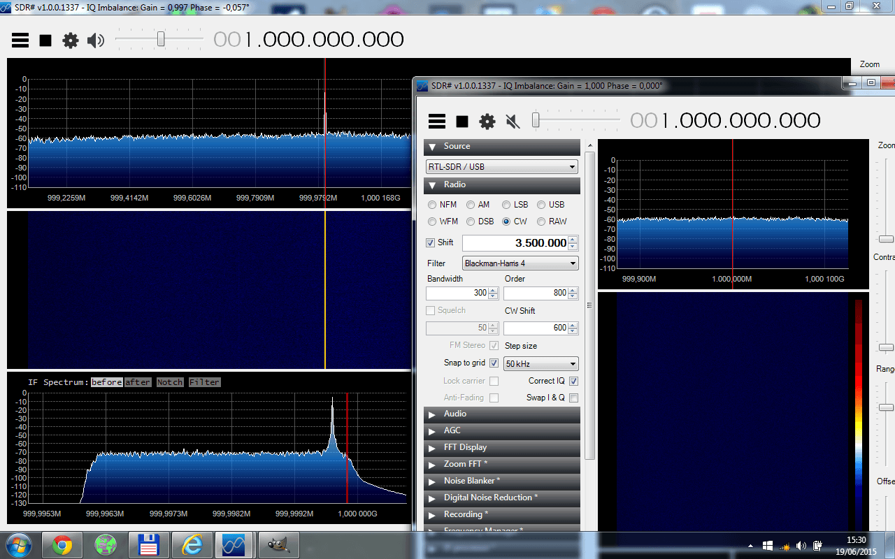
Using SDR# to tune the TX RTL-SDR to 1 GHz, and using another instance of SDR# and another RTL-SDR to receive the transmitted 1 GHz signal.
Update: Oscar has revised the frequency range from 500 – 1500 MHz to 1.8 GHz – 3 GHz. More information about his new tests can be found at http://www.steila.com/SDR/RFgenmod/index.html.
Over on YouTube user kugellagers has uploaded a video showing how he designs and builds a 520 kHz high pass filter for his RTL-SDR dongle + upconverter. In the video he explains how to design the filter with the free Elsie software which is an electrical filter design and analysis program. He then shows how he builds and selects the filter inductors and capacitors and how he assembles the components on a PCB. Finally he demonstrates how his 520 kHz high pass filter is useful for filtering out atmospheric noise from lightning strikes.