Airspy have recently announced on Twitter that they are holding a 30% off Black Friday sale that runs from November 26 to December 2. The coupon is apparently valid from all their distributors which can be found on their purchase page.
Airspy sell a range of software defined radios. The HF+ Discovery is one of the best low cost HF SDRs we've tested, and the Airspy Mini and R2 are good wide band VHF/UHF radios that are a step up from RTL-SDRs. The SpyVerter is a good upconverter that is also compatible with RTL-SDRs, and can be used with the bias tee on the RTL-SDR Blog V3.
The sale brings the pricing down to the following prices in USD (plus shipping costs):
This is probably the cheapest pricing we'll see all year, and last years Black Friday sale was only 15% off, so now's a good time to purchase if you were interested in these products as this is the cheapest pricing we've seen yet.
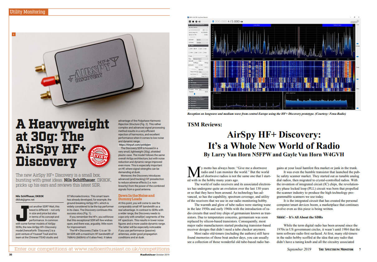
Recently three new reviews of the Airspy HF+ Discovery have come out in various radio enthusiast magazines from around the world. All three reviews have been released for free in PDF form over on the Airspy reviews page. Unsurprisingly each review praises the HF+ Discovery as it's clearly a great radio.
” Most the low-priced SDRs have never been preselected, mostly for cost reasons, and will suffer strong signal overload especially in high RF areas (urban/metro areas). Without exception, these devices usually have major problems with the antennas that radio hobbyist use. They overload very quickly, which makes serious reception on long, medium and shortwaves rather difficult. The HF+ Discovery is the big exception. Based on our testing, the Airspy HF+ Discovery has no equal at its price point. You will find world-class performance and an amazing piece of hardware wrapped up in a package smaller than a matchbox. The Airspy line has a very fine reputation in the radio hobby. In reviews published in Gayle Van Horn’s 2018 Global Radio Guide and the 2019 World Radio TV Handbook, the Airspy HF+ received high marks by the testers and a “Best Value” rating. ”
The second review is by Nils Schiffhauer (DK8OK) which was published in the October 2019 edition of "Radio User". For German readers, Nils also published a similar review written in German for the December edition of "Radio-Kurier".
Just another SDR? Wait, this beast is different – not only in size and price but also in terms of its concept and performance. In common with some former models of AirSpy SDRs, the new AirSpy HF+ Discovery model (henceforth: ‘Discovery’) is a joint venture of Youssef Touil and his team at the Chinese ITEAD studio and ST Microelectronics. This smart team has already developed, for example, the ground-breaking AirSpy HF+, which is widely considered to be the top performer in its class. The Discovery continues this success story.
The Discovery shines with less noise, and, astonishingly, less crackle. In at least 80% of these diffi cult cases, intelligibility with the Discovery is clearly better. With very few stations, this receiver will even make the difference between understanding the identification of a station and not copying it. In August, I also tested the Discovery with the most ‘demanding’ band, the Very Low Frequency range (VLF). Here most SDRs – and certainly the majority of budget SDRs – reach their limits, lacking sensitivity and filling up the band with internally-generated signals. Thanks to a newly developed input section to start at even 500Hz, this receiver shows outstanding strong and clean signals from as far as the US Navy in Australia.
Covers from the Spectrum Monitor and Radio User Airspy HF+ Discovery Reviews
Over on YouTube the TechMinds YouTube channel has uploaded a review of our RTL-SDR Blog L-Band patch antenna which we recently released. TechMinds tests the antenna on a STD-C Inmarsat channel with the Scytale-C decoder, and on various AERO ACARS transmissions with JAERO. Later in the video he also tests the patch antenna on Iridium reception using the Iridium Toolkit software. In all tests the patch is able to suitably receive the signal with either an RTL-SDR or Airspy SDR.
We also wanted to make a note about an additional tip regarding polarization that many people using the antenna seem to have missed. As Inmarsat signals are LHCP polarized, it is important to not only point the antenna towards the satellite, but also to rotate the antenna to match the polarization until maximum SNR is achieved. The rotation can make the difference between strong signals and nothing received at all.
RTL-SDR Active L-Band Patch Antenna For Inmarsat / Iridium / GPS
We've also recently seen a user 'Bert' who has needed to boost the signal strength as he was running the patch inside and at a location in northern Europe with poor reception of Inmarsat. To boost it he simply added a metal horn over the patch made from an old aluminum box, and also a back plate reflector. He notes that this improved his SNR on AERO 10500 from 8 - 9 dB, up to 12 - 14 dB. He also tested using the patch on a dish antenna, and found very good results too.
Aluminum Horn Added to L-Band PatchL-Band Patch Antenna on Dish
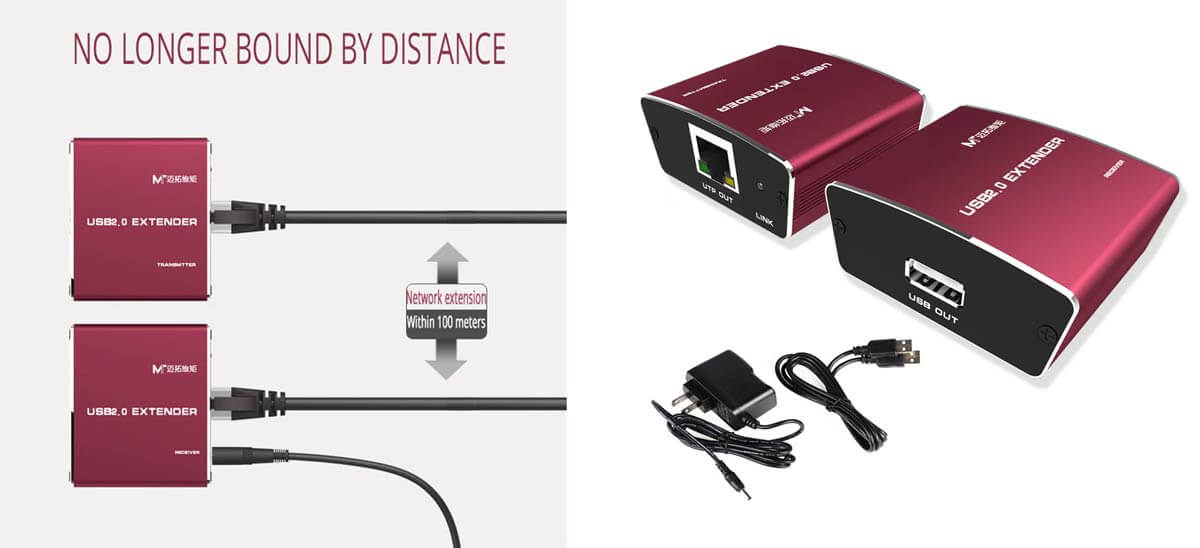
Over on Aliexpress and eBay there are now multiple USB2.0 extenders that work using Ethernet cable. These extenders advertise that is is possible to use up to 100m of Ethernet cable. Extending the USB connection rather than using coax cable is desirable as coax cable introduces signal losses the longer it is. Extending the digital side of the SDR (the USB cable) results in no signal being lost.
However, the USB2.0 specification notes that the maximum limit of the length of an extension cable is only 5 meters. We can go beyond 5 meters by using active repeater cables, but even this has limits of up to 30 meters maximum only.
So how can these USB2.0 Ethernet extenders advertise a length of up to 100m? These devices essentially convert the USB signal into an Ethernet network signal. Ethernet cable for network connections has a limit of 100 meters. Using this Ethernet extender is quite similar to using a Raspberry Pi and running the RTL_TCP software over an Ethernet cable, except that the network connection is handled entirely by the hardware.
We purchased a $45 USB2.0 extender from Aliexpress to test (there is also a cheaper $32 unit that we saw recently that should work too). The extender comes with a 1.5m USB Male to Male cable, a transmit box, a receive box and a 5V plug pack. The transmit side plugs into the PC via the USB Male to Male cable. The receiver end is placed up to 100m away, and this side must be powered by the 5V plug pack. In between you can run up to 100m of Ethernet CAT cabling.
USB2.0 Ethernet Extender from Aliexpress
In our testing we purchased a 50m CAT6 cable and tested to see if the extender would work with an RTL-SDR Blog V3, Airspy and SDRplay. Initially we had trouble getting SDR# to connect to the RTL-SDR. Eventually we found out that the provided USB Male to Male cable provided was of poor quality. After replacing it with a higher quality cable the extender began working properly. We also found that some USB ports on our PC wouldn't run the unit. The USB3.0 ports on the back of the PC connected directly to the motherboard worked best.
USB2.0 Ethernet Extender Test
Using SDR# the RTL-SDR Blog V3 worked exactly like it was connected directly to the PC. There was no lag noticed at all, with tuning being instant. Sample rates up to 3.2 MSPS worked fine, although of course 2.56 MSPS was the limit without drops. As the receiver box is powered by a 5V plug pack, there was plenty of power available to power a 100 mA LNA via the V3's bias tee as well.
Reliability was a bit of an issue. Sometimes we'd need to replug the USB port several times before it would connect to the RTL-SDR. But once running everything appeared to be stable, and we left it running overnight at 2.56 MSPS without any problems.
Unfortunately the lower bit rate and sample rate of the RTL-SDR appears to be the limit of what the extender can handle. The Airspy with it's higher data transfer requirements due to it's 12-bit ADC didn't work properly, with audio stuttering from dropped packets (even at the lower 3 MSPS sample rate with packing enabled). The SDRplay also wouldn't work, with the SDRUno software being unable to detect the RSP1A. Even using a shorter 2M Ethernet cable did not help for these SDRs. In theory it should work since Ethernet can support a much higher data rate, but perhaps the converter chipset used in the cheap extender unit that we have isn't fast enough.
If you want to try this out, be very careful of what you purchase on Aliexpress/eBay/Amazon. There are some very very cheap USB to Ethernet extenders out there that are advertised as USB2.0, but not all of them are truly USB2.0. The very cheap ones under $5 won't work. Those cheap units actually degrade USB2.0 down to USB1.1 which will not work for an RTL-SDR or any other common SDR. The extender units that will probably work properly are all priced over $30.
It's also possible that some of the more expensive units available on Amazon (e.g. [1][2][3]) may be implemented better and might work with the Airspy and SDRplay. If you've tried one of the pricier units please let us know in the comments if it works. In particular this $156 KVM unit which claims a high data rate and also supports PoE may work (although PoE may cause switching noise). For extreme extensions of up to 250m, USB2.0 fiber optic extenders such as this $359 unit, or this $459 fiber optic unit which can go up to 5km (3.1 miles) might also work. If you've tried any of these please let us know in the comments.
Marcus Leech from ccera.ca is a pioneer in using low cost software defined radios for observing the sky with amateur radio telescopes. In the past he's shown us how to receive things like the hydrogen line, detect meteors and observe solar transits using an RTL-SDR. He's also given a good overview and introduction to amateur radio astronomy in this slide show.
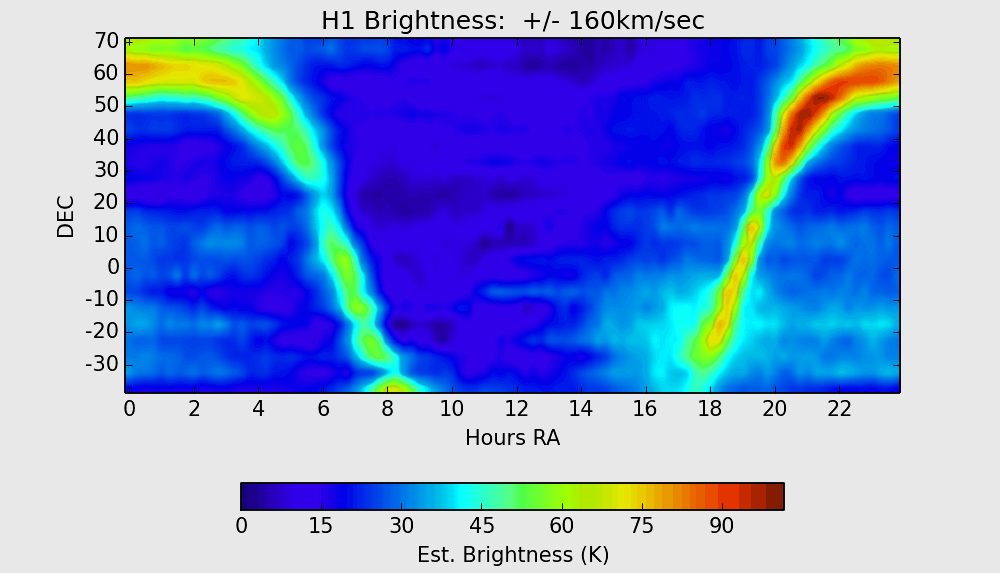
His recent project has managed to create a full Hydrogen sky map of the northern Canadian sky. In his project memo PDF document Marcus explains what a sky map shows:
A [sky map] shows the brightness distribution over the sky for a given set of observing wavelengths. In the case of the 21cm hydrogen line wavelength, maps show the distribution of hydrogen over the sky. For amateur observers, such maps generally show the distribution within our own galaxy, since extra-galactic hydrogen is considerably more faint, and significantly red/blue shifted relative to the rest frequency of 1420.40575 MHz, due to relative motion between the observer and the target extra-galactic hydrogen.
He was able to make this observation using his radio telescope made from a 1.8m dish antenna, a NooElec 1420 MHz SAWBird LNA + Filter, a 15dB line amplifier, another filter and two Airspy R2 software defined radios locked to an external GPSDO. The system runs his custom odroid_ra software on an Odroid XU4 single board computer, which provides spectral data to an x86 host PC over an Ethernet connection.
Over 5 months of observations have resulted in the Hydrogen sky map shown at the end of this post. Be sure to check out his project memo PDF file for more information on the project and how the image was produced. Marcus' blog post over on ccera.ca also notes that more data and different maps will be produced soon too.
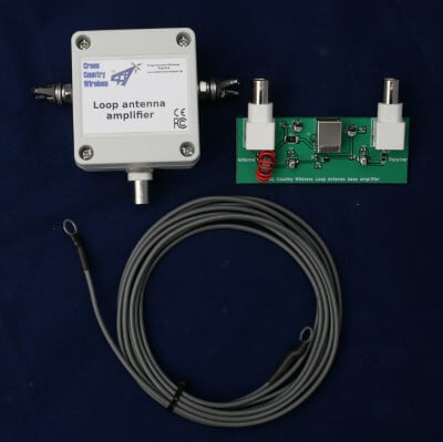
Cross Country Wireless is a UK based company that has created an active HF loop antenna for only $70 USD including international shipping. The loop appears to have already been for sale for a while now, but recently they've created a new version that can be easily powered by a 5V bias tee with at least a 67 mA current capacity. This makes it very easy to use with radios that have built in bias tee's such as our RTL-SDR Blog V3 and SDRplay and Airspy units. The page reads:
The Loop Antenna Amplifier contains all the electronics needed for home DIY construction of an active loop (magnetic loop) low noise receiving antenna.
The amplifier consists of two units, a weatherproofed outdoor unit for connection to a suitable loop and a base unit to further amplify the signal and to provide DC power up the coaxial cable to the outdoor unit.
The outdoor unit is housed in a polycarbonate box with stainless steel antenna connections and a BNC socket. The indoor unit is a PCB with two BNC connectors and a USB socket to take 5V from a USB socket on a PC or phone charger.
Like our other active antenna products it has RF overload protection to allow it to be used very close to transmit antennas without damaging the amplifier or the attached receiver.
The loop depends on what the user has available. We have tested it with simple wire loops or deltas, coax loops and an alloy loop made from a bicycle wheel rim. We supply a 3m (10 ft) length of wire as a simple loop to make a first loop for testing.
The photograph on the right shows the prototype with a 1m diameter loop of LDF4-50 coax cable as a test loop.
With a simple wire loop or delta and a small USB powerbank it makes a very compact and portable receiving antenna for holiday listening or covert use.
The latest version can now have the head unit powered directly from receivers with a 5V bias-tee such as the SDRplay receivers or some RTL-SDR dongle receivers with a bias-tee option.
Specifications:
Frequency range: 10 kHz to 30 MHz
Loop amplifier input impedance: 0.3 ohms
Output impedance: 50 ohms
Supply voltage: 5 V from USB socket or charger
Supply current (head and base unit): 112 mA
Supply current (head unit fed with 5V bias-tee): 67 mA
Loop antenna outdoor unit connectors: Two M6 stainless steel threaded studs and BNC female (RF out 50 ohms)
There is no comparison yet that we've seen on how this loop compares against the cheaper US$45 Chinese made MLA-30 loop. In a previous post Martin (G8JNJ) reviewed the MLA-30 and noted several design flaws after reverse engineering the circuit. He has let us know that he will also be reviewing the Cross Country Wireless Active Loop and will let us know his thoughts in the future.
Cross Country Wireless Loop
Cross Country Wireless Loop Antenna Amplifier VLF test with 1m diameter coax loop
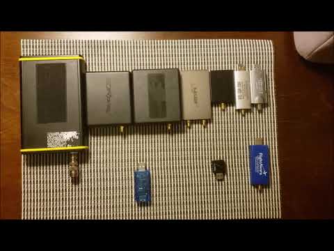
Over on his YouTube channel icholakov has uploaded a video comparing the USB power consumption of various software defined radios. In his tests he uses an inline USB current meter and compares a Perseus, RSP1, RSP1A, Airspy HF+, Airspy HF+ Discovery, RTL V3, Nooelec RTL Mini, Hauppauge 955Q, Flightaware RTL.
If you're only interested in the summary table, then this can be found at 05:49 in the video.
Generally SDRs with better performing tuners and more amplifiers will have higher power requirements, although current consumption can't solely be used to judge performance as some SDRs like the SDRplay make extensive use of filtering to overcome RX performance issues in their tuner. The RTL-SDR V3 and FlightAware dongles have slightly higher current draw compared to the Mini RTL-SDR as they contain an additional HF amplifier and ADS-B amplifier respectively. Lower power consumption may be useful when used with batteries and mobile phones.
2019: Nine SDR Receivers power consumption comparison - how much power does your SDR consume?
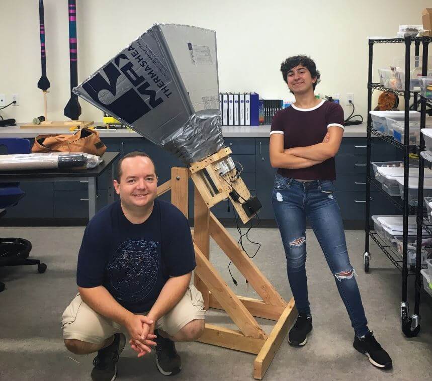
Briefly, their build consists of a horn antenna and reflector designed for the 1,420.4 MHz Hydrogen line frequency. The horn is built out of a few pieces of lumbar, metallic house wall insulation sheets and aluminum tape. The feed is made from a tin can and piece of wire. In terms of radio hardware, they used an Airspy SDR, GPIO labs Hydrogen Line Filter + LNA, and 2x Uputronics Wide band preamps, and a Minicircuits VBF-1445+ filter. For software processing, they used a GNU Radio flowgraph to integrate and record the spectrum.
The results show that they were able to achieve a good hydrogen line peak detection, and they were able to measure the galactic rotation curve doppler shift, and tangent points which prove that we do in fact live in a spiral galaxy.
The Finished Hydrogen Line SDR Based Horn Radio Telescope Antenna