Amateur radio astronomer Marcus Leech often makes use of RTL-SDR dongles for his amateur radio astronomy experiments. Recently Marcus wrote a technical paper discussing a modern SDR implementation of a Dicke Radiometer, which is a type of radio telescope that is designed to significantly reduce the effects of receiver noise. Marcus has also developed an RTL-SDR approach to another similar system called the Phase-Switched Interferometer.
Using his new SDR based approach together with GNU Radio, a 10ft satellite dish and two RTL-SDR dongles he was able to plot a transit of the Milky Way Galaxy as shown below.
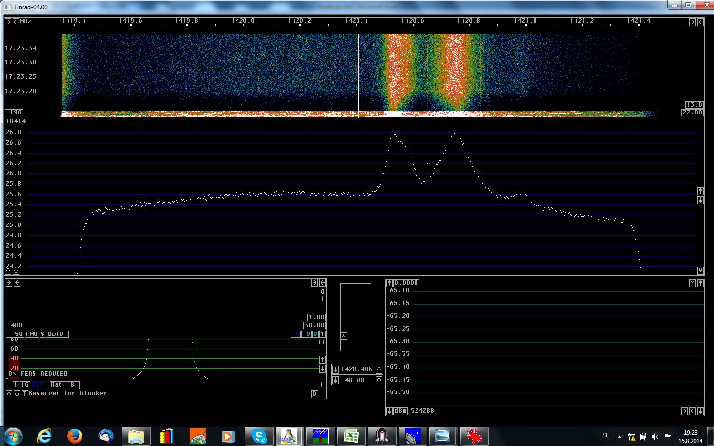
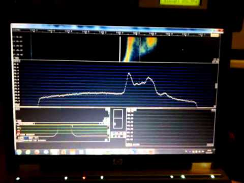
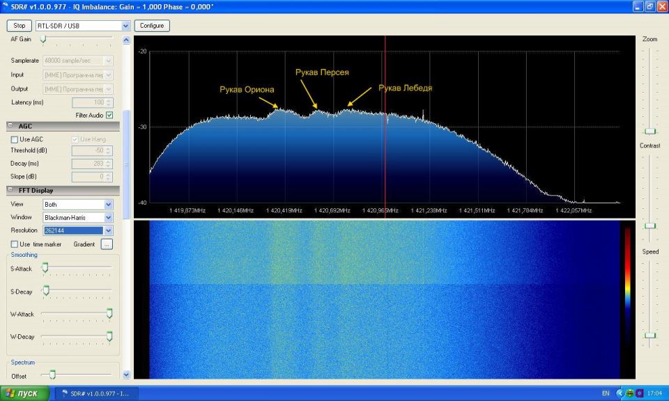
Over on YouTube user S53RM has uploaded a video showing his and S53MM’s observation of the 1420 MHz galactic hydrogen line with an RTL-SDR. Hydrogen atoms randomly emit photons at a wavelength of 21cm (1420.4058 MHz). Normally a single hydrogen atom will rarely emit a photon, but since space and the galaxy is filled with many hydrogen atoms the average effect is an observable RF power spike at 1420.4058 MHz. By pointing a radio telescope at the night sky, a power spike indicating the hydrogen line can be observed in a frequency spectrum plot.
In the video they rotate their 3.6m parabolic mesh antenna dish along the Milky Way. As the dish rotates doppler shifted hydrogen line peaks can be observed on Linrad, each peak representing a different arm of the galaxy. The galaxy consists of several spinning arms, some spinning faster than others which causes the hydrogen line peaks produced by the arms to be doppler shifted by different amounts.
They used Linrad to plot the RF spectrum as they were able to use it together with a pulse generator to calibrate the RTL-SDR for a flatter frequency response.
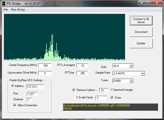
Amateur radio astronomy hobbyist Jim Sky has written on his blog about his new program called RTL Bridge with allows the RTL-SDR to directly connect to his other radio astronomy programs Radio-SkyPipe and Radio-Sky Spectrograph. Jim describes his two existing program as follows.
Radio-Sky Spectrograph displays a waterfall spectrum. It is not so different from other programs that produce these displays except that it saves the spectra at a manageable data rate and provides channel widths that are consistent with many natural radio signal bandwidths. For terrestrial , solar flare, Jupiter decametric, or emission/absorption observations you might want to use RSS.
Radio-SkyPipe is a souped-up strip chart program which plots signal strength over time. When getting its data from RTL Bridge, RSP is plotting the total power in the spectrum covered by the RTL receiver centered around its set frequency. While the raw values are proportional to power, you will have to apply a function via the RSP Equations feature to apply a calibration if you want absolute values. For signals that do not have significant spectral structure of interest, this would be the preferred way to plot the data.
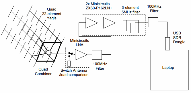
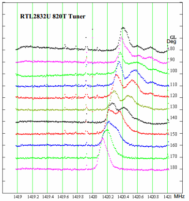
Amateur radio astronomer Y1PWE has uploaded a pdf document describing how he created a low cost hydrogen line telescope using an RTL-SDR dongle (links under heading 2. H-Line Receiver) . Hydrogen atoms randomly emit photons at a wavelength of 21cm (1420.4058 MHz). Normally a single hydrogen atom will rarely emit a photon, but since space and the galaxy is filled with many hydrogen atoms the average effect is an observable RF power spike at 1420.4058 MHz. By pointing a radio telescope at the night sky, a power spike indicating the hydrogen line can be observed in a frequency spectrum plot.
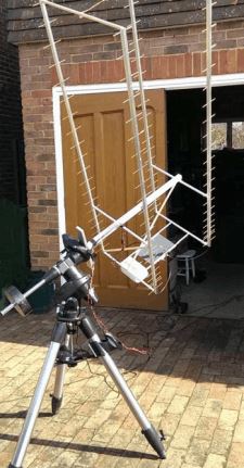
Y1PWE created a radio telescope using a quad 22 element yagi antenna, several LNA's and filters and an RTL-SDR dongle and laptop. Using this setup he can capture some raw IQ data from the RTL-SDR and then use an FFT averaging program to produce some plots. In his plots the hydrogen line is clearly visible.
The LNB converts input frequencies of 12.2 GHz to 12.7 GHz down to 950 MHz to 1.45 GHz which is a range that the RTL-SDR can receive. In his YouTube video posted below David points his Itty Bitty Radio Telescope at the sun and shows the associated increase in the noise floor on SDR# due to solar radio emissions. More information and possible experiments with the Itty Bitty Radio Telescope can be found in this PDF.
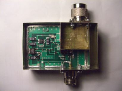
At the center of his system is an LNA with 40dB gain and a very low noise figure of 0.2dB. This LNA appears to be based on G4DDK’s VLNA, but modified to work with the 1420 MHz frequency used for radio astronomy. It seems the LNA can be ordered for 140 USD from the above link.
Note: The above Russian links are machine translated with Google to English.
There is an amateur radio group in Germany known as DL0SHF which transmits a 10 GHz (QRG = 10.368.025 MHz) beacon at the moon whenever it is visible at their site. The goal of this transmission is to detect the very weak beacon reflection.
Amateur radio hobbyist Rein (W6SZ) has written in to let us know about his, DK7IJ’s and the DL0SHF groups success with receiving the beacon using the RTL-SDR. He writes
DL0SHF transmit a signal to the moon when the moon is visible at the site. The run 2 modes 50 and 500 W output, 20 seconds on, 40 seconds off.
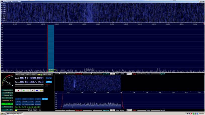
Last night, I managed to detect the beacon with a very simple receiving package. Amazing enough, using WSJT moon tracking data, the signal appeared right away when the moon appeared here above the trees.
The signal lasts only 20 seconds but then 40 seconds later, it returned! By the books.
I use a simple 10 GHz receiver here that I use for scouting signals on 10 GHz terrestrial as member of the San Bernardino Microwave Society.
It consists of a RTL Dongle IF block tuned to 618 MHz as IF.
Front-end is a PLL LNB, not modified, running with 9.750 GHz LO
The LNB is powered with 12 Volts by means of a Bias Tee.
Both items can be acquired for about USD 25.- on eBay and other places.
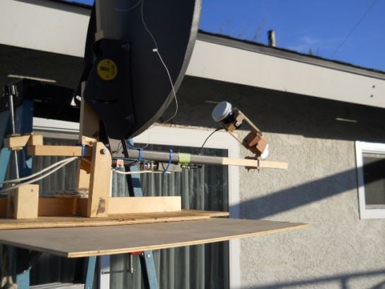
The antenna is a standard 18 inch satellite off-set dish.
The antenna has some elevation control and the feed ( LNB ) can be rotated for polarity control.
Every variable is manually operated.
At times I measured the beacon as high as 15 dB above the noise using HDSDR as DSP processor software.
The beacon was running in the 500 W output mode during these observations.
Moon bounce visible on the waterfallMoonbounce Equipment Setup
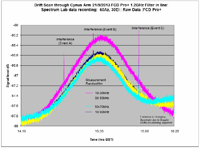
Dr Morgan uses his Funcube dongle with the SpectrumLab Windows software, which is a specialized audio analyzer. For the hardware, David uses a 3m focal plane dish antenna and a 1200 MHz high pass filter.
The paper goes into good detail about some of the technical side of radio astronomy, shows how to calibrate the telescope using the sun and also shows several measurements made. We note that the same procedures could also likely be done with the RTL-SDR.
Signal Intensity during Drift Scan through Cygnus Spiral Arm