A Multi-Channel Coherent RTL-SDR Product: For Passive Radar, Direction Finding and More
Coherent-receiver.com is a company which is a customer of our RTL-SDR V3 dongle and they have been working on creating a multi-channel coherent receiver product based on the RTL-SDR. An RTL-SDR multi-channel coherent receiver is at its most basic, two or more RTL-SDR dongles (multi-channel) that are running from a single clock source (coherent). A multi-channel coherent receiver allows signal samples from two different antennas to be synchronized against time, allowing for all sorts of interesting applications such as passive radar and direction finding.
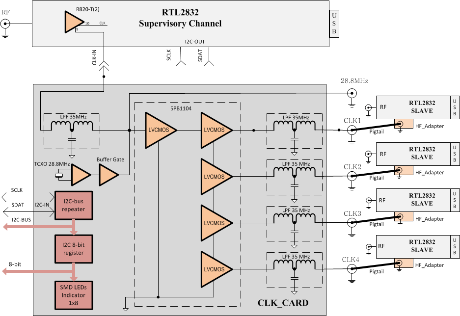
The team at coherent-receiver.com have used the new expansion headers on our V3 dongles to create their product. In their receivers they attach a control board which has a buffered 0.1 PPM TCXO (buffered so it can power multiple RTL-SDR’s). They also added an 8-bit register and I2C connection capabilities which allows for control of future add-on boards. The I2C capability is useful because it means that several RTL-SDR dongles can be controlled and tuned from the same control signal. More information on the registers and build of the receiver control board can be seen on their technical support page.

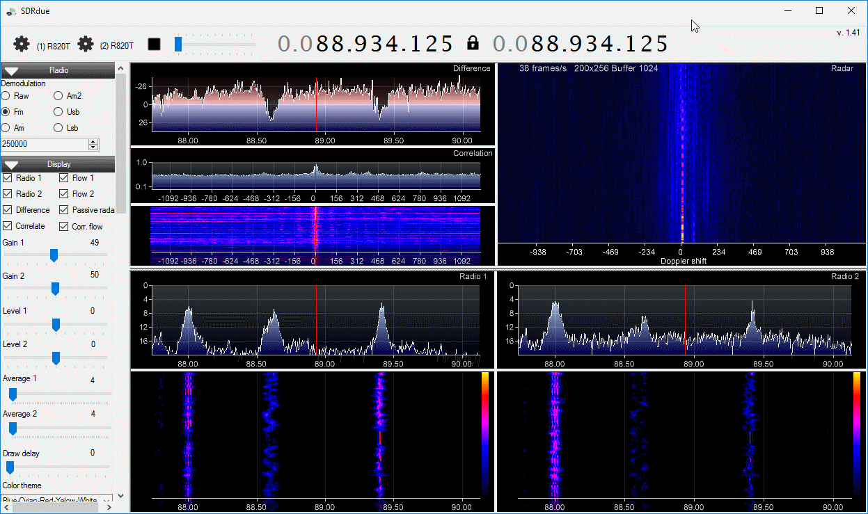
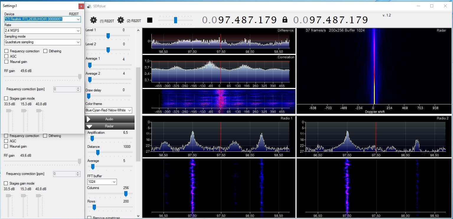
One example application of a multi-channel coherent receiver is passive radar. Coincidentally, we’ve just seen the release of new GUI based Passive Radar software by Dr. Daniel Michał Kamiński in yesterdays post. Passive radar works by listening for strong signals bouncing off airborne objects such as planes and meteors, and performing calculations on the signals being received by two antennas connected to the multi-channel coherent receiver.
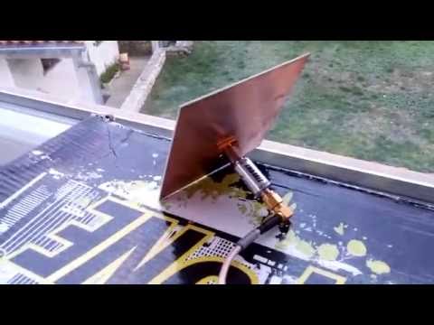
A second example is direction finding experiments. By setting up several antennas connected to a multichannel coherent receiver calculations can be made to determine the direction a signal is coming from. An interesting example of direction finding with three coherent RTL-SDRs can be seen in this previous post. A third example application is pulsar detection which we have seen in this previous post.
Coherent-receiver.com sent us a prototype unit that they made with four of our V3 dongles. In testing we found that the unit is solidly built and works perfectly. We tested it together with Dr. Kamiński’s passive radar software and it ran well, however we do not have the correct directional antennas required to actually use it as a passive radar yet. In the future we hope to obtain these antennas and test the coherent receiver and the software further.
Currently they do not have pricing for these models as it seems that they are first trying to gauge interest in the product. If you are interested in purchasing or learning more they suggest sending an email to [email protected]. It seems that they are also working on additional RTL-SDR ecosystem products such as filters, downconverters, antennas and LNAs.
We hope that the release of this product and Dr. Kamiński’s software will give a boost to the development of coherent multi-channel receivers as we have not seen much development in this area until recently.