A Geostationary Satellite Imaged with the RTL-SDR Based Mini Radio Telescope
Just a few days we posted an update on the PICTOR open source radio telescope project. That project makes use of an RTL-SDR and a small dish antenna to receive the Hydrogen line, and is able to measure properties of our galaxy such as determining the shape of our galaxy.
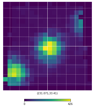
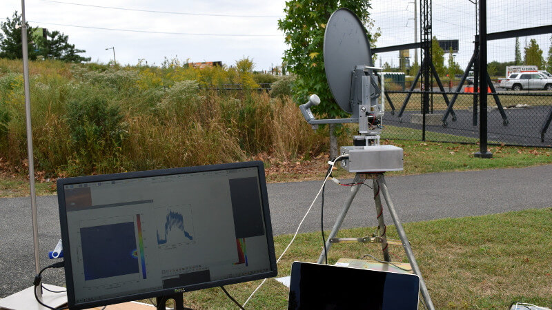
Now over on Hackaday another amateur radio telescope project has been posted, this one called the "Mini Radio Telescope" (MRT) which was made by Professor James Aguirre of the University of Pennsylvania. This project makes use of a spare Direct TV satellite dish and an RTL-SDR to make radio astronomy observations. What makes this project interesting in particular is the automatic pan and tilt rotor that is part of the design. Unlike other amateur radio telescopes, this motorized design can track the sky, and map it over time. This allows you to create actual radio images of the sky. The image on the right shows a geostationary satellite imaged with the dish.
In the past we saw a similar project by the Thought Emporium YouTube channel which used a tracking mount and a HackRF to generate images of the WiFi spectrum. This was to be a precursor to a motorized tracking mount for radio astronomy but it doesn't seem that they completed that project yet.
Professor James Aguirre 's project including designs for the rotor is fully open source and can be found over on GitHub.
Cross Country Wireless is a UK based company that has created an active HF loop antenna for only $70 USD including international shipping. The loop appears to have already been for sale for a while now, but recently they've created a new version that can be easily powered by a 5V bias tee with at least a 67 mA current capacity. This makes it very easy to use with radios that have built in bias tee's such as our RTL-SDR Blog V3 and SDRplay and Airspy units. The page reads:
The Loop Antenna Amplifier contains all the electronics needed for home DIY construction of an active loop (magnetic loop) low noise receiving antenna.
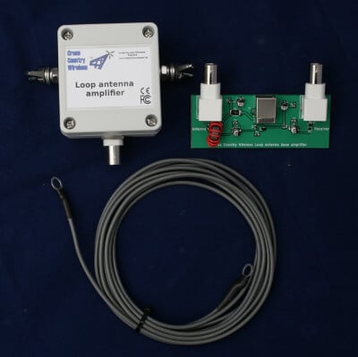
The amplifier consists of two units, a weatherproofed outdoor unit for connection to a suitable loop and a base unit to further amplify the signal and to provide DC power up the coaxial cable to the outdoor unit.
The outdoor unit is housed in a polycarbonate box with stainless steel antenna connections and a BNC socket. The indoor unit is a PCB with two BNC connectors and a USB socket to take 5V from a USB socket on a PC or phone charger.
Like our other active antenna products it has RF overload protection to allow it to be used very close to transmit antennas without damaging the amplifier or the attached receiver.
The loop depends on what the user has available. We have tested it with simple wire loops or deltas, coax loops and an alloy loop made from a bicycle wheel rim. We supply a 3m (10 ft) length of wire as a simple loop to make a first loop for testing.
The photograph on the right shows the prototype with a 1m diameter loop of LDF4-50 coax cable as a test loop.
With a simple wire loop or delta and a small USB powerbank it makes a very compact and portable receiving antenna for holiday listening or covert use.
The latest version can now have the head unit powered directly from receivers with a 5V bias-tee such as the SDRplay receivers or some RTL-SDR dongle receivers with a bias-tee option.
Specifications:
Frequency range: 10 kHz to 30 MHz
Loop amplifier input impedance: 0.3 ohms
Output impedance: 50 ohms
Supply voltage: 5 V from USB socket or charger
Supply current (head and base unit): 112 mA
Supply current (head unit fed with 5V bias-tee): 67 mA
Loop antenna outdoor unit connectors: Two M6 stainless steel threaded studs and BNC female (RF out 50 ohms)
There is no comparison yet that we've seen on how this loop compares against the cheaper US$45 Chinese made MLA-30 loop. In a previous post Martin (G8JNJ) reviewed the MLA-30 and noted several design flaws after reverse engineering the circuit. He has let us know that he will also be reviewing the Cross Country Wireless Active Loop and will let us know his thoughts in the future.
Cross Country Wireless Loop
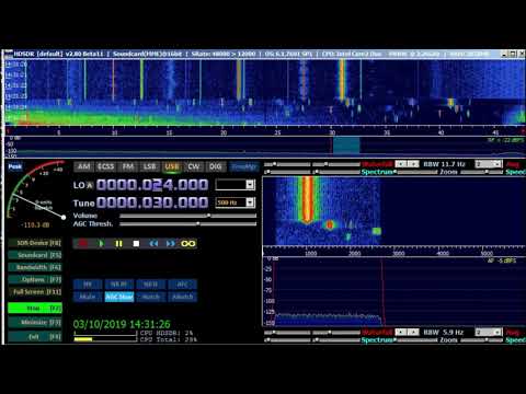
Cross Country Wireless Loop Antenna Amplifier VLF test with 1m diameter coax loop
Back in July we posted about PICTOR, an open source and RTL-SDR based radio telescope project. The owner of the project recently wrote in and wanted to share some updates. His text is below:
The goal of this effort is to introduce students, educators, astronomers and others to the majesty of the radio sky, promoting radio astronomy education, without the need of building a large and expensive radio telescope.
Since the initial launch, PICTOR has gotten lots of updates and improvements, particularly in the software backend, providing more data to the users, using advanced techniques to increase the signal-to-noise ratio by calibrating spectra and mitigating radio frequency interference (RFI) (if present).
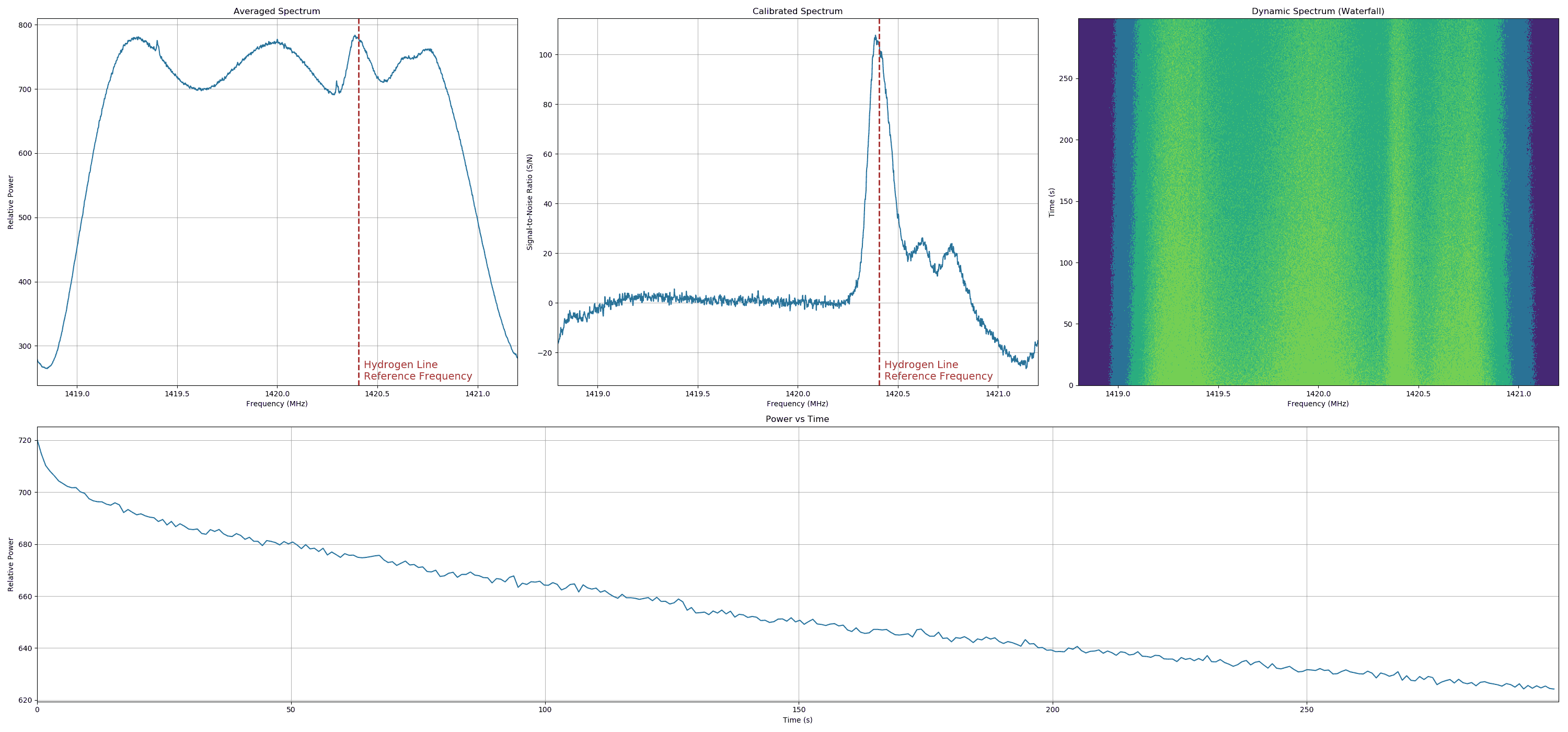
Here is an example observation with PICTOR, clearly showing the detection of 3 hydrogen-dense regions corresponding to 3 unique spiral arms in the Milky Way!
Graphs from the PICTOR RTL-SDR Radio Telescope showing the 3 unique spiral arms in the Milky Way.
Just a heads up that the preorder sale on our new L-Band Patch antenna set will be ending October 21 as we are almost ready to ship the units out. After the preorder sale ends the pricing will rise from $34.95 to $39.95 USD.
Preorder has now ended and shipping will begin shortly. Thank you!
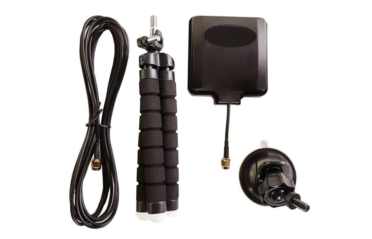
The product is a ready to use active patch antenna set that is designed to receive L-Band satellites such as Inmarsat, Iridium and GPS. It is enclosed in a waterproof plastic case, and can easily be mounted to a window using the provided suction cup and 2M coax extension cable. It can also be mounted to almost anything else using the included flexible tripod legs, or if you prefer, use the standard 1/4" camera screw hole to connect it to any mount that you like.
The antenna is powered via 3.3V - 5V bias tee power, so any bias tee capable SDR such as our RTL-SDR Blog V3 can be used to power it.
Over on his YouTube channel Corrosive from the SignalsEverywhere YouTube channel has uploaded a video where he tests out the new US$29.95 NooElec PCB patch antenna for receiving L-band satellite signals. In the video he shows how it can be combined with one of their SAWBird L-band low noise amplifiers in order to receive L-band satellite signals such as Inmarsat STD-C and AERO.
We note that our own RTL-SDR Blog Active L-band patch antenna will be ready to ship out before the end of this month, and while waiting for it we are currently having a preorder sale for US$34.95 including free shipping over on our store. For US$34.95 our patch antenna is fully contained in a waterproof enclosure, includes an LNA built in, and comes with several mounting options, so we believe that it is really a great deal. The patch design is based on the Outernet ceramic patch that was compared against the NooElec PCB patch shown in Corrosives video, so performance will be very similar.
Nooelec NEW Inmarsat Patch Antenna with Airspy SDR
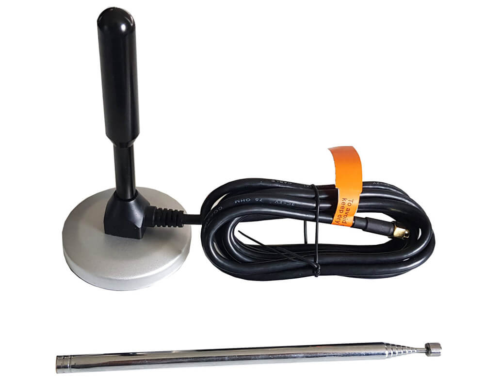
We've recently released a new Magnetic Whip Antenna Set in our store. The set consists of a heavy duty magnetic mount antenna base with 2M RG59, a 9.5cm fixed whip antenna (usable from 400 MHz to 2 GHz+), and a 17cm to 1m telescopic whip (usable from 100 MHz - 400 MHz).
The antenna set costs US$14.95 each with free shipping. And if you buy four sets you will receive a 15% discount. Currently available to ship worldwide right now from our warehouse in China, and they will be on Amazon in 2-3 weeks.
One application of our KerberosSDR 4-Tuner Coherent RTL-SDR is radio direction finding. This requires four quality omni-directional antennas. We were disappointed to find that there were no high quality magnetic whip antennas available on the market for a low price that we could use with KerberosSDR so we made our own.
The magnetic base is designed carefully with conductive metal that is properly connected to the shield of the coax cable. Most cheap antenna bases just leave the shield connection floating and this causes insufficient coupling to the underlying ground plane resulting in poor performance and poor results when it comes to direction finding and reception.
We've tested this set with KerberosSDR and it is known to work well. The antenna can also of course be used for any other receiving purpose if you prefer to use a whip antenna over our multipurpose dipole antenna set.
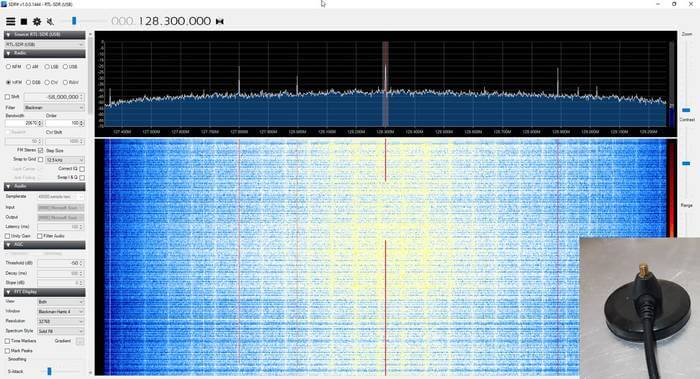
In the first two images in the image slider below you can see a comparison between a black base that is not properly bonded to the coax shield, vs the RTL-SDR Blog silver base which is correctly bonded to the coax shield. Both tests used the 9.5cm whip antenna. You can see that the RTL-SDR Blog silver base provides a much lower noise floor and higher signal SNR due to the better ground plane. Also we note that when placing the antenna bases on a metallic surface to create a larger ground plane, the black base showed no further improvement, whereas the RTL-SDR Blog silver base did.
The final three images in the slider show the SWR plots of the two whips on the base. We can see that the 9.5cm whip provides an SWR of less than six below 412 MHz. The telescopic whip can be adjusted to provide better SWR for lower frequencies.
Last month we posted a collection of reviews about the MLA-30 which is a budget magnetic loop antenna designed for receiving HF signals. The overall consensus from the reviews was that it worked decently for the price, but of course could never live up to the high end loops that cost hundreds of dollars.
Recently Martin (G8JNJ) reverse engineered the active circuit used on the loop from photos taken by M0LMK and has made some observations on it's performance, noting that it's design isn't very good. First he notes that the amplifier chip is a Texas TL592B two stage video amplifier which isn't that great for this application. His measurements show an OIP3 of 20dBm, a P1 saturation of -3dBm and a noise figure of 12dB.
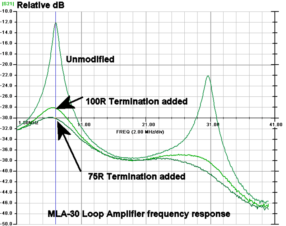
Of interest, he explains that the creator of this loop has designed it poorly as the impedance match of the loop to low pass filter is very wrong, resulting in a very poor amplitude/frequency response. He shows how the response can be improved with a few termination resistors, but is still not great.
MLA-30 Frequency Response. Ideally should be flat.
If you're interested in a cheap magnetic loop antenna, Martin suggests DIYing the M0AYF design which he says works a lot better.
We note that the "YouLoop" design is also in the works as a product that will apparently sell at close to manufacturing cost. The YouLoop is a passive loop idea by the creator of the Airspy that consists only of a simple 1:1 transformer and coax cable as the loop. It works best with high sensitivity radios like the HF+ Discovery.
Over the last several months we've been working on a versatile active L-band patch antenna that can cover Inmarsat to Iridium satellite frequencies. That antenna is now almost ready, and should be able to ship out from our Chinese storage warehouse by week 1 or 2 of October NOTE: Due to an unfortunate Typhoon near the factory in Taiwan, and the Chinese National Week long holidays and Taiwan National day we are expecting them to ship out in week 3 or 4 of October now. Apologies for the delays. No other components like filters or amplifiers are required to be able to use this antenna, as it is an all in one system.
The expected price will be US$39.95, but right now we're releasing it for a discounted PREORDER price of US$34.95 incl. free shipping.
Preorder sale has ended. Please see our store to order.
Your preorder will ship out as soon as it's stocked in the warehouse in China. If you prefer to wait we'll also have this product on Amazon (at retail $39.95) about 2-3 weeks after it is stocked in our Chinese warehouse.
The antenna is based on the active (low noise amplified with built in filter) ceramic patch design that was used by Othernet (aka Outernet), back when they had their L-band service active. We've asked them to modify the antenna to cover a wider range of frequencies, and include an enclosure that allows for easier mounting.
The antenna is 3.3 - 5V bias tee powered, so you will need a bias tee capable RTL-SDR like our RTL-SDR Blog V3, or a 5V external bias tee. It draws about 20-30mA of current, so it is compatible with other SDRs like the SDRplay, HackRF and Airspy too.
With this antenna we've paid close attention to the mounting solutions. One major difficulty with these patch antennas is finding a convenient place to mount them. The patch is designed with a built in 1/4" camera screw hole, so any standard camera mount can be used. In the kit we're including a window suction cup, a flexible tripod and 2 meters of RG174 cabling to help with mounting. Your own longer coax cabling can be used, however we'd recommend using lower loss cabling like RG59/58 or RG6 for anything longer than 3 meters.
The patch is also fully enclosed in an IP67 weather proof plastic case, so it can be kept mounted outdoors in the rain.
The RTL-SDR Blog L-Band Satellite Patch Antenna SetWays to mount the patch antenna
Performance
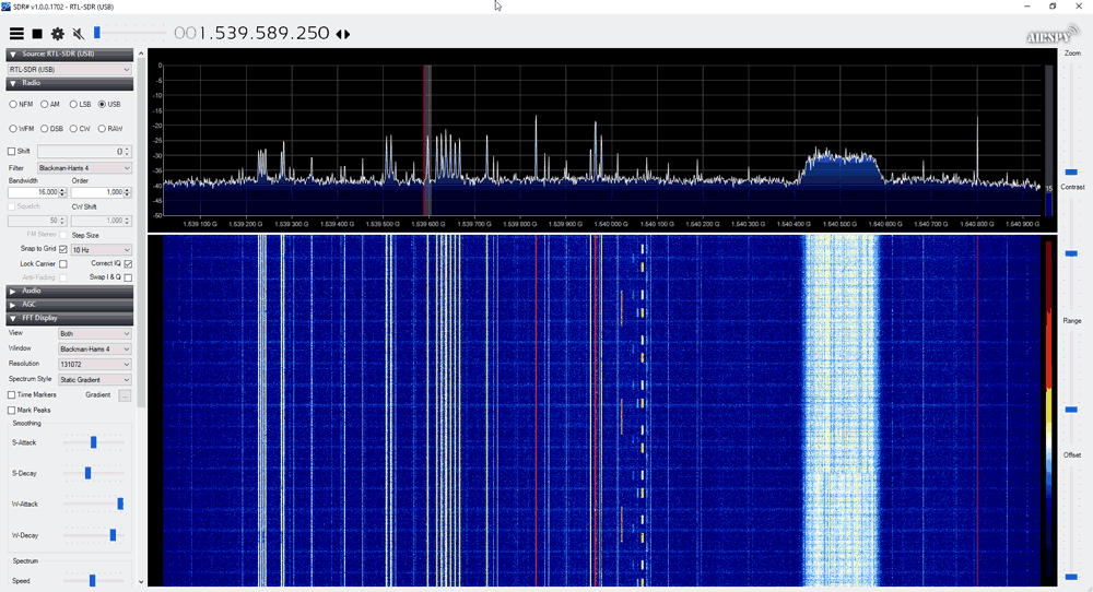
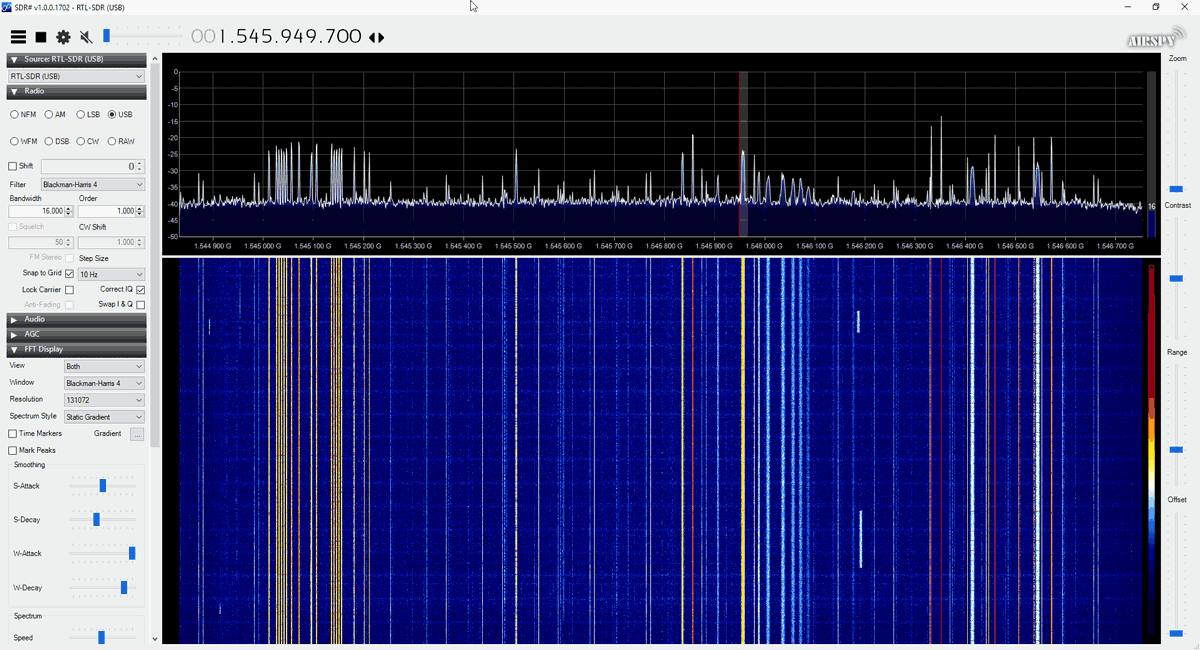
With the patch receiving AERO, STD-C and GPS should be a breeze. Simply point up at the sky, or towards the Inmarsat antenna, apply bias tee power and receive. Below are some sample screenshots showing reception.
The patch is designed to be used with a 1m+ length of coax cable. It may perform poorly if the RTL-SDR is placed right at the antenna due to interference.
If receiving Inmarsat, the patch antenna should ideally be angled to face the satellite.
Rotate the patch until the signal strength is maximized. Rotating the patch optimizes the polarization of the antenna for the satellite and your location. NOTE: Using the wrong orientation could result in 20 dB attenuation, so please do experiment with the rotation.
You can also use the patch on a flat surface for Inmarsat (and rotate for best reception), but signal strength may be a little reduced. Depending on your location and the satellites elevation it should still be sufficient for decoding.
For receiving Iridium and GPS signals you can use the antenna flat, pointing straight up towards the sky. Try to get it seeing a clear view of the sky horizon to horizon to maximize the satellites that it can see.
If you happen to have a very marginal signal, you can clamp on a flat sheet of metal behind the patch antenna for improved performance.
AERO C-Channel: C-Channel transmissions are at 1647-1652 MHz which are outside of the advertised range of this antenna. However, the filter cut off is not that sharp, and you may be able to get results, although we cannot guarantee this. (If you want to test this for us and can demonstrate that you can receive C-Channel already, please contact us at [email protected] for a sample)