Note: This post is now old (written in 2014). As of mid 2015 the latest version of DSD+ can be downloaded from www.dsdplus.com. Also note that in 2015 DSD+ changed their version numbers for some reason, so 1.5 is actually older than 1.1.
Version 1.5 of Digital Speech Decoder Plus (DSD+) has been released. DSD+ is a popular Windows software tool used for decoding digital speech such as P25 with the RTL-SDR. The latest version comes with a simple GUI interface that has an event log that shows call target and source ID history and an audio waveform plot which can help determine if DSD+ is receiving audio correctly. This version of DSD+ has the ability to decode the following protocols.
D-STAR
NXDN4800
NXDN9600
DMR/MotoTRBO
P25 Phase 1
X2-TDMA
ProVoice
In addition to the above, the new version comes with an LRRP decoder and display program which should allow you to see on a map the GPS location of broadcasting radios.
DSD+ V1.51 can be downloaded from this link (UPDATE: dead link, use www.dsdplus.com now). The forum thread on RadioReference where the developer releases and discusses the DSD+ software can be found here.
This version of DSD+ comes with all the files needed to make it run already. To use DSD+ V1.5 simply extract the zip file into a folder and double click on DSDPlus.EXE. DSD+ will listen to your default audio device that is set in the Windows sound recording properties. Simply tune to a digital voice signal in SDR# or any other SDR receiver and set the output audio settings accordingly. To start the LRRP display program simply open LRRP.exe.
Some car security systems from around 2001 – 2003 use an embedded RFID tag inside the car key as an added security measure against key copying. Using his HackRF, ChiefTinker was able to analyse and decode the data from an active RFID token used in a car key. He notes that the same analysis could also be performed with an RTL-SDR dongle.
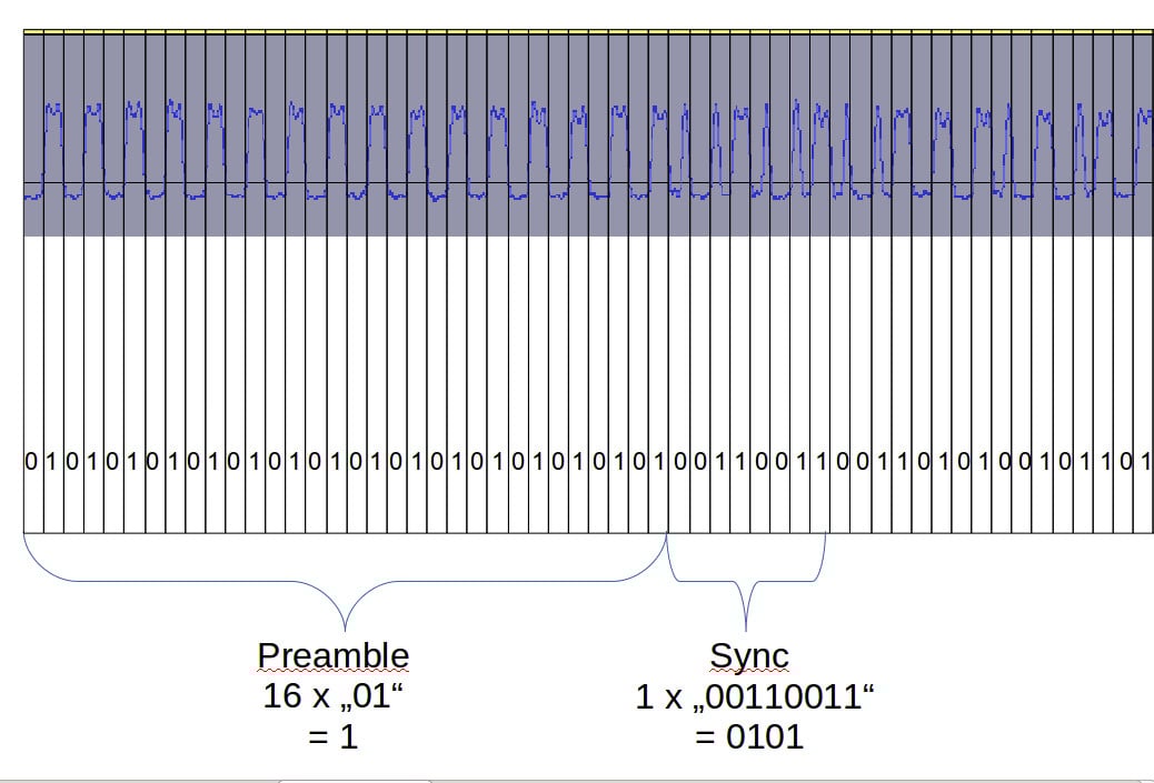
Upon powering the RFID tag with a power supply, ChiefTinker noticed that the tag emitted a short transmission every 5 seconds in the ISM band at 433.920 MHz. On closer inspection he determined that the transmitted data was encoded with a simple AM on-off keying (OOK) scheme. After importing the audio into Audacity and cleaning up the signal a little, he was able to clearly see the OOK square wave showing the transmitted binary data.
Next he analysed the data and compared the binary output against two different RFID keys. From the comparison he was able to determine that the tag simply beacons a unique serial number, which is susceptible to capture and replay attacks. After further processing he was able to convert the transmitted binary serial number into hexadecimal, then ASCII to find the unique serial number being broadcast in decimal.
With the launch of Meteor M2-3, the loss of all prior Meteor M satellites and the release of new software, this tutorial is now outdated. We will eventually update this tutorial, but for now we will reference this post which has a brief high level overview of how to receive and decode images from the Meteor M2-3.
The Meteor-M N2 is a polar orbiting Russian weather satellite that was launched on July 8, 2014. Its main missions are weather forecasting, climate change monitoring, sea water monitoring/forecasting and space weather analysis/prediction.
The satellite is currently active with a Low Resolution Picture Transmission (LRPT) signal which broadcasts live weather satellite images, similar to the APT images produced by the NOAA satellites. LRPT images are however much better as they are transmitted as a digital signal with an image resolution 12 times greater than the aging analog NOAA APT signals. Some example Meteor weather images can be found on this page and the satellite can be tracked in Orbitron or online.
The RTL-SDR and other SDRs like the Funcube along with some free software can be used to receive and decode these images. LRPT images from the Meteor-M N2 are transmitted at around 137.925 MHz, so any satellite antenna like those commonly used with the NOAA weather satellites can be used.
NOTE:Meteor M1 has come alive, (now offline again), so the frequency of Meteor M2 was changed from 137.1 MHz to 137.9 MHz.Meteor M1 is now at 137.1 MHz and can be received using the same steps as in this tutorial, though please note that images from Meteor M1 are not perfect since the satellite is tumbling.
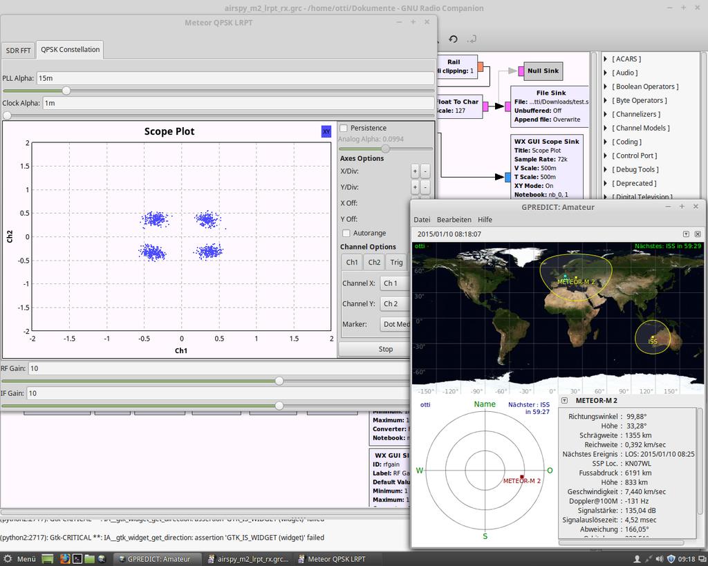
Happysat, a satellite monitoring enthusiast has emailed us with a comprehensive tutorial showing how the RTL-SDR can be used to receive and decode these LRPT images (pdf warning) (txt file). The procedure is not quite as simple as with the NOAA satellites as it involves first pre-recording the transmission as a baseband I/Q file in SDR#, changing the sample rate in Audacity, processing the file with the Lrptrx.exe software, and then using Oleg's LRPToffLineDecoder (now called M2_LRPT_Decoder) to finally produce the image (in case the link is down for LRPToffLineDecoder/M2_LRPT_Decoder), try mirror here or here).
The tutorial also shows an alternative and faster Linux based method using some GNU Radio scripts, but with the final processing still done with Oleg's decoder in Windows.
Update:This newer post now shows a slightly faster way for receiving and decoding LRPT images on a Windows PC which does not require the use of Audacity.
Basic idea on Linux is to record an IQ wav file using:
The Meteor-M2 SatelliteAn Example LRPT Image Received with an RTL-SDR from the Meteor-2 M2.Another Sample LRPT ImageWhat a LRPT signal looks like in SDR#
For a comprehensive book about the RTL-SDR you may be interested in our eBook available on Amazon.
The second plugin is a Digital Code Squelch (DCS) decoder plugin. The plugin will display the DCS codes that are transmitted with the signal and will display all possible compatible codes. DCS is a squelching system similar to CTCSS which allows for radio user sharing by ensuring that radio users are not bothered by communications not intended for them. The DCS Decoder plugin can be downloaded from http://www.rtl-sdr.ru/page/novyj-plagin-dcs-decoder (note page in Russian).
Digital Code Squelch (DCS) Decoder Plugin for SDR#
There is a war going on between game console designers and the console modding community. Modders hack the console system so that they can jailbreak it and then install their own custom firmware while console designers are constantly finding new ways to prevent unauthorized modding. Custom firmware allows a console to run homebrew applications like media players and emulators that use the console in ways that is was not intended to be used in. One PlayStation 3 modder has recently been using an RTL-SDR to help jailbreak a PlayStation 3 Super Slim (4K) console, whose current official firmware appears to not yet have been jailbroken. It’s important to note that so far no actual jailbreaking has been done with this method, but the modder is currently working on it. His idea is to receive leaked RF signals from the PS3 and then use methods similar to Acoustic Cryptoanalysis to decode the data and find out what opcode operations the processors are performing. The modder writes about his method in the following.
My idea was to hook up a rtl-sdr device to the PS3 4k between chassis and real ground (yes, I actually have a two meter copper rod buried in my lawn) using the antenna leads. First I had to make sure the PS3 4k chassis wasn’t grounded in the outlet, and that no video out or USB connector was hooked up to ground indirectly via other hardware. If you want to try this, make sure that the rtl-sdr antenna leads are the only lead between the PS3 mobo/chassis and real ground. Before connecting the rtl-sdr antenna leads I measured the voltage on the PS3 chassis which peaked at around 1.8V which was safe enough, didn’t want to blow it up on the first try.
This method will effectively turn your console into an “active antenna” leaking all kind of interesting data on the rtl-sdrfrequency spectrum (between 24 – 1766 MHz). After hooking it up, I started using gqrx on my laptop to look for signal peaks while the PS3 4k was turned on, after finding a peak I just powered off the PS3 completely and turned it back on, using the waterfall plot you’ve seen in my first post I can see if there is something interesting happening during boot and verify that the signal is indeed coming from the PS3. In a similar way I learned to distinguish between the PS3 BD drive, GPU and CPU which pops up at different frequencies. Then I dumped the data (I/Q recording) that looked interesting and made a note of the frequency.It’s hard to describe the incredible feeling when you tune into a good signal and start watching the waterfall plot revealing opcodes, register bits and what might be stack contents. The Acoustic Cryptoanalysis paper (PDF) has a lot of good info how to interpret the output from various window functions in the plot. What I’m coding right now is a gnuradio-companion block which will filter and test the dumped data for decryption keys against encrypted PS3 data.
PS3 Data Received with an RTL-SDR and shown on a GQRX Waterfall
Over on YouTube user John Miller has uploaded a video showing an example of DSD+ decoding an NXDN96 voice signal. NXDN is a digital voice protocol by developed by Kenwood that is often used by public safety organizations.
John uses SDR# to receive the NXDN signal and then pipes the audio to DSD+ using Virtual Audio Cable for decoding.
The popular YouTube electronics channel Hak5 has uploaded a video showing how they analyzed GSM signals using an RTL-SDR, Wireshark and Airprobe. In their video they use parts of our analyzing GSM tutorial and explain and show visually how to set up all the software.
Using these methods they were able to receive GSM data from a base tower and see various system information.
Using A RTL-SDR To Learn About The GSM Network Around You, Hak5 1621
At Tel-Aviv University in Israel, two students undertook a class project where they were able to use an RTL-SDR to record a garage door opener signal and then use a Texas Instruments (TI) Chronos watch to retransmit a copy of the signal. Their report can be found here (pdf). The TI Chronos is a wrist watch with a built in programmable ISM band RF transmitter.
The students report contains an analysis of the signal which may be of use to anyone interested in decoding their own ISM band signals and they also describe a method used to automatically obtain the required parameters for programming the TI Chronos with the signal to be copied. The abstract of their report is as follows
We present a simple and affordable way of copying remote controls widely used for parking lot gates, garage doors and other simple systems. These simple remote controls usually use a fixed code (as opposed to the more secured rolling code used for car keys remote controls) and a simple On-Off Keying (OOK) modulation, over 433.92MHz in the ISM band. We suggest the use of the TI-Chronos wrist-watch platform for the emulation of the remote control, as this platform transmits in the same band, and can be programmed to emulate different modulations and to send user pre-defined signals.
In this report we show the complete process for copying a remote control into the Chronos platform. This process utilizes only a standard PC and low-cost hardware (less than $75 all together), alongside free software, and additional software developed by us. The process starts with recording the original remote control RF signal. It continues with automatic analysis of the recording, extracting the needed parameters of the signal. Finishing the process, we set the Chronos with those parameters. We demonstrate the copy process using a 4-channel remote control and its receiver board.