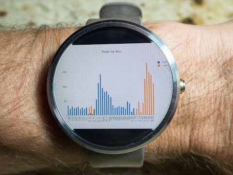
To gather the power usage data he used an RTL-SDR connected to a PC running rtlamr, which is software that can read data from ERT compatible power meters that transmit in the 900 MHz ISM band. He also uses some custom code he wrote that automatically plots the data over time and allows him to integrate it with his home automation system. In addition to his post he also uploaded a video shown below that shows his system in action.
Monitoring house power using a $20 RF RTLSDR USB stick
Over on YouTube user Jane feverlay has uploaded a video showing a new AIS decoder called AISRec for Windows that he has developed.
AIS is an acronym for Automatic Identification System and is a system used by ships to broadcast position and vessel information. By monitoring AIS transmissions with the RTL-SDR we can build a boat radar system. We have a tutorial on this here.
The new software is not free, but he offers a trial version that limits the run time to 20 minutes and 5000 max messages. The paid version removes these limits and also decodes both AIS channels simultaneously. The program monitors data from the RTL-SDR and sends decoded data out via UDP. Software such as OpenCPN can then be used to display the AIS data on a map.
We tested the trial version on our machine and found that it worked well at decoding AIS messages. To download the trial go to http://pan.baidu.com/s/1pJiEzEV and enter the code kn44. The download site is in Chinese, but it is obvious where to enter the code. We found the software to be virus free, but remember to always scan unknown software like this yourself. The full price of the software is unknown, but purchasing instructions are given in the trial download readme. The author also writes that his software now supports the Airspy, but not in the trial version.
Note that we discovered that the software doesn’t use a PPM correction setting as expected. Instead it uses a frequency shift setting. To set the shift in the AISRec.ini file, we had to calculate freqshift = 162.025 MHz – frequency of the second AIS channel as shown in SDR# with no PPM correction set.
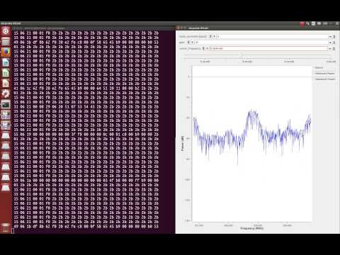
Over a year ago we wrote a tutorial on how to analyze GSM cellular phone signals using a RTL-SDR, a Linux computer with GNU Radio, Wireshark and a GSM decoder called Airprobe. With this combination it is possible to easily decode GSM system messages. Setting up Airprobe is can be difficult as it is unmaintained and incompatible with the new version of GNU Radio without patches.
Now a new software package called gr-gsm has been released on GitHub which seems to be a newer and improved version of Airprobe. The gr-gsm software is also much easier to install, uses the newer GNU Radio 3.7 and seems to decode the system data with much less trouble than Airprobe did. We will soon update our tutorial to use gr-gsm, but the instructions on the GitHub are already quite good. The author of gr-gsm also appears to be actively adding new features to the software as well. The video below shows gr-gsm in action.
Sniffing GSM data with gr-gsm and cheap RTL-SDR receivers
NOTE: There is now a plugin available for SDR# that will decode TETRA fairly easily. It is still in beta and misses a few features found in telive. Check it out in this post.
TETRA is a trunked radio communications system that stands for "Terrestrial Trunked Radio". It is used heavily in many parts of the world, except for the USA. Recently, a software program called Tetra Live Monitor (telive) was released on GitHub. This software can be used along with the (patched) Osmo-TETRA software to monitor and listen to unencrypted TETRA communications.
Below we show a tutorial on how to listen to TETRA communications using a RTL-SDR RTL2832U software defined radio. This tutorial is based heavily on the telive_doc.pdf file that is written by the author of telive and included in the telive git download. Please refer to that pdf file for further details on how the software works. We have modified their tutorial slightly to make it a little easier to understand. As this code is still under heavy development if you have trouble please check their PDF file for modifications to the procedures.
Most of this tutorial is performed in Linux and we assume that you have some decent Linux experience. We also assume you have some experience with the RTL-SDR dongle and have a decent antenna capable of picking up TETRA signals in your area. If you don't have a RTL-SDR dongle yet see our Buy RTL-SDR dongles page.
Note: As of October 2016 there is now a Windows port of the Telive decoding software available. This may be an option for you if you prefer to run in Windows. More information here.
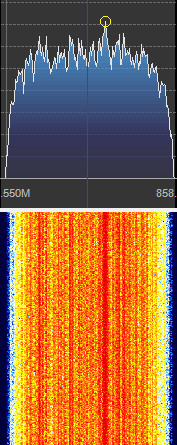
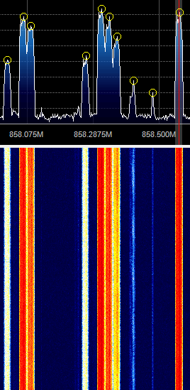
First, we will need to find some TETRA signals. The easiest way to do this is to open SDR# or another program like GQRX and look for them. TETRA signals are continuously broadcasting with a bandwidth of around 25 kHz. In most European countries they can be found at 390 - 470 MHz. In some countries they may be found around 850 MHz or 915 - 933 MHz. There may be several TETRA signals grouped in close proximity to one another. See the example images below.
A Zoomed in TETRA Signal
A Grouping of TETRA Signals Zoomed Out
An example audio clip of a TETRA signal recorded in NFM mode is shown below.
Once you have found some TETRA signals, record their frequencies. Now close SDR#, or whatever software you were using and boot into Linux. In this tutorial we use a 32-bit Ubuntu 14.04 virtual machine running on VMWare Player as our Linux system. Some of the commands may vary if you are using a different system.
Note: This post is now old (written in 2014). As of mid 2015 the latest version of DSD+ can be downloaded from www.dsdplus.com. Also note that in 2015 DSD+ changed their version numbers for some reason, so 1.5 is actually older than 1.1.
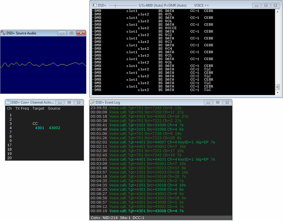
Version 1.5 of Digital Speech Decoder Plus (DSD+) has been released. DSD+ is a popular Windows software tool used for decoding digital speech such as P25 with the RTL-SDR. The latest version comes with a simple GUI interface that has an event log that shows call target and source ID history and an audio waveform plot which can help determine if DSD+ is receiving audio correctly. This version of DSD+ has the ability to decode the following protocols.
D-STAR
NXDN4800
NXDN9600
DMR/MotoTRBO
P25 Phase 1
X2-TDMA
ProVoice
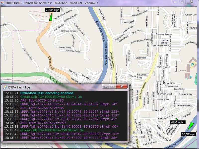
In addition to the above, the new version comes with an LRRP decoder and display program which should allow you to see on a map the GPS location of broadcasting radios.
DSD+ V1.51 can be downloaded from this link (UPDATE: dead link, use www.dsdplus.com now). The forum thread on RadioReference where the developer releases and discusses the DSD+ software can be found here.
This version of DSD+ comes with all the files needed to make it run already. To use DSD+ V1.5 simply extract the zip file into a folder and double click on DSDPlus.EXE. DSD+ will listen to your default audio device that is set in the Windows sound recording properties. Simply tune to a digital voice signal in SDR# or any other SDR receiver and set the output audio settings accordingly. To start the LRRP display program simply open LRRP.exe.
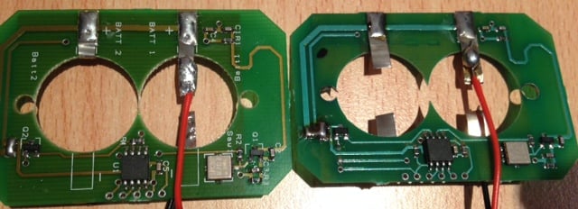
Some car security systems from around 2001 – 2003 use an embedded RFID tag inside the car key as an added security measure against key copying. Using his HackRF, ChiefTinker was able to analyse and decode the data from an active RFID token used in a car key. He notes that the same analysis could also be performed with an RTL-SDR dongle.
Upon powering the RFID tag with a power supply, ChiefTinker noticed that the tag emitted a short transmission every 5 seconds in the ISM band at 433.920 MHz. On closer inspection he determined that the transmitted data was encoded with a simple AM on-off keying (OOK) scheme. After importing the audio into Audacity and cleaning up the signal a little, he was able to clearly see the OOK square wave showing the transmitted binary data.
Next he analysed the data and compared the binary output against two different RFID keys. From the comparison he was able to determine that the tag simply beacons a unique serial number, which is susceptible to capture and replay attacks. After further processing he was able to convert the transmitted binary serial number into hexadecimal, then ASCII to find the unique serial number being broadcast in decimal.
With the launch of Meteor M2-3, the loss of all prior Meteor M satellites and the release of new software, this tutorial is now outdated. We will eventually update this tutorial, but for now we will reference this post which has a brief high level overview of how to receive and decode images from the Meteor M2-3.
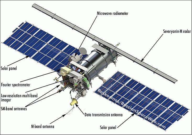
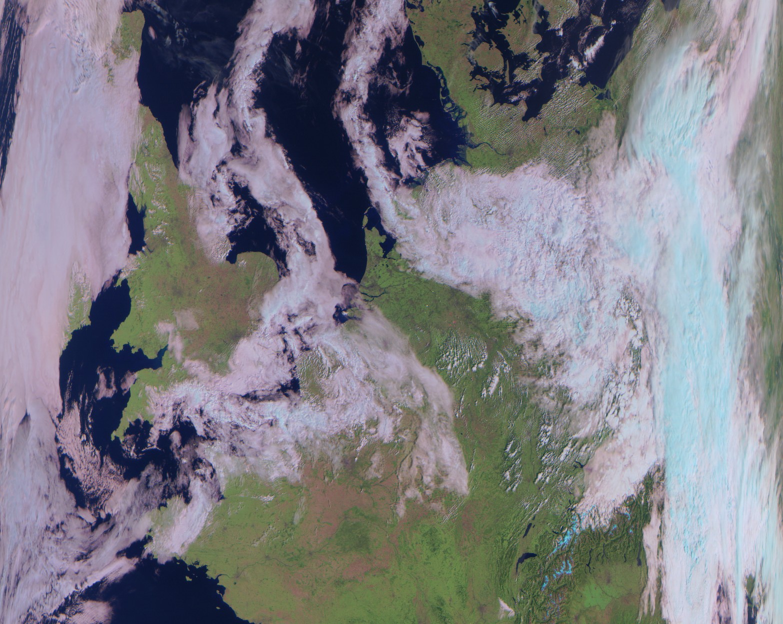
The Meteor-M N2 is a polar orbiting Russian weather satellite that was launched on July 8, 2014. Its main missions are weather forecasting, climate change monitoring, sea water monitoring/forecasting and space weather analysis/prediction.
The satellite is currently active with a Low Resolution Picture Transmission (LRPT) signal which broadcasts live weather satellite images, similar to the APT images produced by the NOAA satellites. LRPT images are however much better as they are transmitted as a digital signal with an image resolution 12 times greater than the aging analog NOAA APT signals. Some example Meteor weather images can be found on this page and the satellite can be tracked in Orbitron or online.
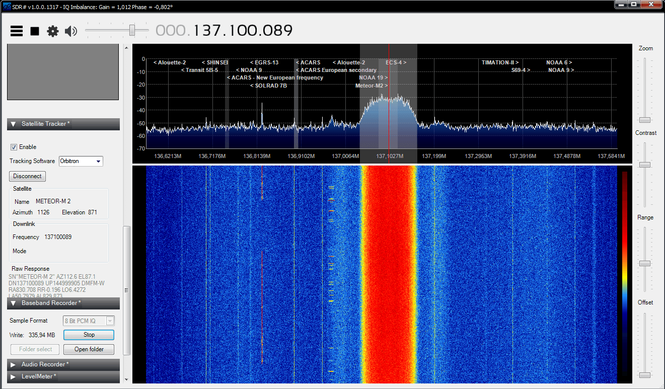
The RTL-SDR and other SDRs like the Funcube along with some free software can be used to receive and decode these images. LRPT images from the Meteor-M N2 are transmitted at around 137.925 MHz, so any satellite antenna like those commonly used with the NOAA weather satellites can be used.
NOTE:Meteor M1 has come alive, (now offline again), so the frequency of Meteor M2 was changed from 137.1 MHz to 137.9 MHz.Meteor M1 is now at 137.1 MHz and can be received using the same steps as in this tutorial, though please note that images from Meteor M1 are not perfect since the satellite is tumbling.
Happysat, a satellite monitoring enthusiast has emailed us with a comprehensive tutorial showing how the RTL-SDR can be used to receive and decode these LRPT images (pdf warning) (txt file). The procedure is not quite as simple as with the NOAA satellites as it involves first pre-recording the transmission as a baseband I/Q file in SDR#, changing the sample rate in Audacity, processing the file with the Lrptrx.exe software, and then using Oleg's LRPToffLineDecoder (now called M2_LRPT_Decoder) to finally produce the image (in case the link is down for LRPToffLineDecoder/M2_LRPT_Decoder), try mirror here or here).
The tutorial also shows an alternative and faster Linux based method using some GNU Radio scripts, but with the final processing still done with Oleg's decoder in Windows.
Update:This newer post now shows a slightly faster way for receiving and decoding LRPT images on a Windows PC which does not require the use of Audacity.
Basic idea on Linux is to record an IQ wav file using:
The Meteor-M2 SatelliteAn Example LRPT Image Received with an RTL-SDR from the Meteor-2 M2.Another Sample LRPT ImageWhat a LRPT signal looks like in SDR#
For a comprehensive book about the RTL-SDR you may be interested in our eBook available on Amazon.
The second plugin is a Digital Code Squelch (DCS) decoder plugin. The plugin will display the DCS codes that are transmitted with the signal and will display all possible compatible codes. DCS is a squelching system similar to CTCSS which allows for radio user sharing by ensuring that radio users are not bothered by communications not intended for them. The DCS Decoder plugin can be downloaded from http://www.rtl-sdr.ru/page/novyj-plagin-dcs-decoder (note page in Russian).
Digital Code Squelch (DCS) Decoder Plugin for SDR#