Listening to July’s Arecibo Observatory Ionospheric Heating Campaign

During July 24-31 the large Arecibo Radio Observatory in Puerto Rico (the big dish antenna that you may be familiar with from the movie ‘Contact’) ran an Ionospheric heating experiment which involves transmitting 600kW of net power up into the Ionosphere. This type of experiment is used for researching plasma turbulence in the ionosphere and upper atmosphere.

“The new Arecibo ionosphere HF heater nominally transmits 600 kW net power and has a unique Cassegrain dual-array antenna design that increases gain of three crossed dipoles for each band, using the signature 1000-foot spherical dish reflector,” explained Chris Fallen, KL3WX, a researcher at the University of Alaska-Fairbanks HAARP facility. He has reported that Arecibo would use 5.125 or 8.175 MHz, depending upon ionospheric conditions, but emphasized that these are estimates and frequencies may be adjusted slightly. On July 25, Arecibo was transmitting on 5.095 MHz.

Over on YouTube Mike L. used his SDRplay RSP1 together with our BCAM HPF to record some transmissions from the observatory.

Z33T’s Review of the ColibriNANO: $350 USD 10 kHz – 55 MHz SDR Dongle

Over on YouTube Mile Kokotov (Z33T) has uploaded his review of the ColibriNANO, which is a $350 USD 10 kHz – 55 MHz direct sampling SDR dongle built by Russian company Expert Electronics. It features a 14-bit direct sampling ADC which is then decimated into 16-bits at bandwidths of up to 3 MHz, or 24-bits at up to 768 kHz. This should give it excellent dynamic range preventing any sort of overloading.

In the video Mile gives the Colibri an excellent rating. In the video description he writes:

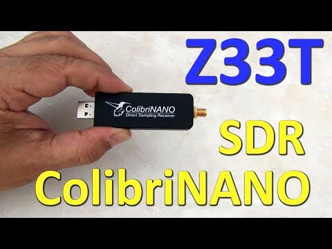
The Colibri-NANO USB stick is a powerful direct sampling SDR receiver with frequency range from 10 kHz to 55 MHz. ColibriNANO is not another cheap USB dongle found on e-bay. This high quality SDR receiver has been developed by Expert Electronics and has strongly and solidly build aluminum body, Electrostatic discharge (ESD) protection, USB 2.0 interface and a quality SMA antenna connector.

ColibriNANO has 14 bit Ananalog-To-Digital Converter, with a clock frequency of 122.88 MHz. Coverage is 10 kHz to 55 MHz, with low pass RF-filter on 55 MHz to protect from strong FM transmitters. The filter can be turned off so you can use the receiver in undersampling mode up to 500 MHz. In that case external filters and preamlifier (like the 2m filtered preamplifier from the same producer) is recommended for maximum results.. 

This excellent little SDR-receiver has nine IQ sample rates, from 48 kHz to 3 MHz so the frequency span on the spectrum window can be changed from 48 kHz up to 3 MHz.

There are no bandpass filters in the device, So one can think that a 14-bit Analog-To-Digital Converter may be subject to overload if you have powerful transmitters nearby. But the software has extensive RF gain control, so you should not have to worry too much. 
As I said before the Analog-to-Digital Converter in this wonderful SDR-receiver uses 14 Bit, and with decimation process results in an excellent 110 dB Blocking Dynamic Range. 

Another nice feature of the ColibriNANO SDR is the combined attenuator/pre-amplifier stage, which can be fine-adjusted in 0.5 dB steps from -31 to +6 dB. Together with the low noise floor and an excellent sensitivity, the result is a receiver with excellent large signal handling capabilities. The ColibriNANO is a perfect HF little SDR scanner which can be compare with much more expensive 
The Colibri-NANO can be operated directly attached to the computer of the user, or can be used remotely at a distant location. This is done with the freely available ExpertRemote software. 

At the location of the SDR a small computer is required (for example a Raspberry-Pi) and for the internet connection can be used a relatively slow internet link. This, for example, allows you to use the SDR receiver at some quiet location anywhere on the world.
Expert Electronics Software for the ColibriNANO allows you to use all the potential of the receiver: remote operation, synchronization with the transceiver, IQ channel bandwidth up to 3 MHz, control of the preamplifier and LPF and so on…

All mode for demodulation are supported. Here are Some of the software features:
– IQ output via Virtual Audio Cable
– Compatibility with any sound card installed on your PC for the audio output
– Synchronization with transceivers via CAT interface
– Remote operation with the ColibriNANO receiver 
– Special interface to control the CW Skimmer
– Screen resolution Supports FullHD and 4K monitors

And the important thing is that All new versions of the software are free!

To control the ColibriNANO via Internet you need freely available ExpertRemote system, based on the client-server connection. This system allows you to place the receiver and server in the remote location with low RF-noise but has the internet connection. This might be some remote village or place with no electrical interference and 3G/4G Internet (or any other connection type). 

Using the ExpertRemote system you can enjoy in clear noiseless reception from your phone, tablet, notebook or PC. Even simple antennas, placed in a “quiet” place, allows you to listen weak signals from the DX-stations better than in urban area filled with all kind of RF-noise.

Another feature of this system is that the receiver’s software can be synchronized with transceivers and be used as the panorama adapter with high resolution. In that way you can use the transceiver to transmit signals, and receive on your remotely located receiver via the ExpertRemote system. 

The ColibriNANO can be used with third party software like HDSDR etc.
You can find more information about this great 14 bit SDR-receiver on Expert electronics official website.
If you are interested in Radio technic and electronics fell free to visit my web-pages: www.qsl.net/z33t

This device appears that it will soon compete with the Airspy HF+ which is an upcoming SDR that claims similar performance for HF. We will work on comparing the two in a later review post.

ColibriNANO SDR-Receiver REVIEW

A Homebrew One Transistor Upconverter for the RTL-SDR

Recently Qrp Gaijin wrote in to us and wanted to share his experiences on building a one transistor diode-ring mixer upconverter for his RTL-SDR. An upconverter for the RTL-SDR translates low HF frequencies ‘up’ into ones that are receivable by the RTL-SDR. This is a different method to the direct sampling mode used in the V3 dongles to achieve HF reception.

Qrp Gaijin’s post goes into some detail about his circuit and shows the schematic as well. He also shows the results with an active loop antenna, RTL-SDR and the upconverter in some videos. In the email to us he also notes that his upconverter is still a work in progress as the LO is quite noisy and he suspects that it may be too weak to drive the 1N4148 based diode ring mixer. There is also no filtering on the circuit yet, so there is some broadcast FM breakthrough.

Another project he worked on was attempting the direct sampling mod on a standard RTL-SDR. However, Qrp Gaijin’s method is slightly different to most attempts as instead of soldering the wires into the Q-branch holes he simply uses hot glue to hold them mechanically in place. This may be an idea to consider for those who want to attempt the mod on a standard RTL-SDR, but don’t have any soldering tools or experience.

Homebrew RTL-SDR upconverter: physical construction

Receiving SSTV Images from the ISS with a V-Dipole and RTL-SDR

During July 20 – 24, 2017 the ISS (International Space Station) was transmitting SSTV (Slow Scan Television) images down to earth in celebration of the ARISS (Amateur Radio on the ISS) 20th Anniversary. The ISS transmits SSTV images on celebratory occasions several times a year. More information about upcoming ARISS events can be found on their website ariss.org.

Over on YouTube and his blog, user Tysonpower has created a video and writeup of his experiences with receiving the ISS SSTV images using an RTL-SDR, FM Trap filter and a V-Dipole antenna. The V-Dipole antenna is a super simple satellite antenna for NOAA/Meteor/ISS etc satellites that recently became popular due to Adam 9A4QV’s writeup on it.

Despite Laptop and PC troubles, he was able to capture several images. He also notes that he was able to use a Baofeng and Yagi antenna to receive the signal indoors.

Note that Tysonpower’s YouTube video is narrated in German, but there are English subtitles available if you turn on YouTube’s closed captions which should be on by default on this video.

[EN subs] ISS SSTV Event Juli 2017 - Empfang von drinnen und V-Dipole

Configuring OpenWRT and RTL_TCP for WiFi Streaming

In his last video YouTube user GusGorman402 showed us how to install OpenWRT and the RTL-SDR drivers on a cheap used $20 router. The idea is that the router with custom third party Linux firmware can be used as a remote device for streaming raw data from an RTL-SDR over a network connection. Normally something like a $35 Raspberry Pi is used for something like this, but an old router could be cheaper and should have even better network performance as it is designed for high data rates (assuming the CPU on your router is powerful enough to run the RTL-SDR).

In his new video Gus shows how to properly configure OpenWRT and RTL_TCP for WiFi streaming of radio data. This includes things like setting up port forwarding and determining network performance.

We’ve also seen this post by GoJimmyPi which was inspired by Gus’s original video. This is a text and screenshot based tutorial which goes through the same process.

Configuring OpenWrt and RTL_TCP for wifi

SDRTrunk Setup and Use Tutorial

Over on his blog John Hagensieker has uploaded a tutorial that shows how to set up SDRTrunk with RTL-SDR dongles. SDRTrunk is an application that allows you to follow trunked radio conversations, and decode some digital voice protocols such as P25 Phase 1. It is similar to Unitrunker and DSDPlus combined into one program. It is also Java based so it is cross platform and so can be used on Linux and MacOS systems as well.

John’s tutorial contains many useful screenshots, so it should be great for a beginner. He starts from the beginning, with finding trunking frequencies over on radioreference.com, then goes on to the installation and use on Linux. He also later explains how the Airspy can be used instead of multiple RTL-SDR to cover 10 MHz of bandwidth so that multiple systems can be monitored.

SDRTrunk Running and decoding a P25 Phase 1 System

Potentially Receiving up to 10 GHz with an RTL-SDR and Multiple SUP-24000 Downconverters

Back in 2016 KD0CQ discovered that a $5 DirectTV device with model name SUP-2400 could be used as a downconverter with an RTL-SDR for receiving frequencies of up to 4.5 GHz. A downconverter is a device that converts high frequencies such as 4.5 GHz down into a frequency actually receivable by the RTL-SDR. The SUP-2400 is able to be modified into a useful downconverter by opening it up and manually removing some mixing harmonic filters.

In his latest post KD0CQ shows how you could combine four modified SUP-2400 downconverters to create a quarduple conversion mixer which allows you to receive up to 10 GHz. The post goes into the mixing math and practicalities of this idea. KD0CQ writes that some amplification will most likely be required to push the signal through, and in the past he’s managed to receive up to 7.5 GHz.

The SUP-2400 Directv upconverter that can be converted into a downconverter.
The SUP-2400 DirecTV device that can be converted into a downconverter.

Comparing a FM Coax Notch Filter vs Lumped Elements FM Bandstop Filter

Over on his YouTube channel Adam 9A4QV has uploaded a video that compares a coax notch filter and lumped elements filter band stop for the FM band. Bandstop filters are useful as they can be used to block out extremely strong signals that can overload an SDR dongle (or any radio).

A coax notch is a very simple band stop filter that is made from a length of coax cable at 1/4 wavelength of the frequency that you want to block. Just connect the 1/4 wavelength coax with a T-junction connector and you’ll get a notch at the frequency you want to block. A lumped elements filter is one made out of inductors and capacitors. Designing this type of filter generally requires a few more calculations, and ideally simulation. Then building it is a bit more difficult as you either need to buy or make the inductors, and then solder them together.

But as Adam shows in the video coax notch filters have a problem in that the notch is not only at the exact frequency that you want to block. Instead there will be multiple odd spaced harmonics of the blocking frequency as well. For example if your desired notch is at 100 MHz, you’ll also get notches at 300 MHz, 500 MHz, 700 MHz and so on. So a coax notch filter still needs to be carefully designed to not block out your frequency of interest.