Back in February of this year we first heard about the Airspy HF+, which is an upcoming product from the Airspy team that is intended to be a high performance HF receiver at a low price. Over on the Airspy HF+ website the first (rendered) image of the unit has recently been released. We’ve also managed to get some additional renderings from the Airspy team which we show in the image slider below.
The enclosure is CNC carved aluminum with two SMA ports on one side, and a USB port on the rear. Since the HF+ actually has the capability to tune up to 260 MHz it uses two SMA inputs, one for an HF antenna and one for a VHF antenna. Inside the RF circuit is shielded again with a shielding can to protect it from USB noise.
The tweet below also appears to show some grounding improvements made to reduce USB noise.
The Airspy HF+ is also the result of a long learning journey and a great attention to details. USB noise is past! cc @ITeadstudiopic.twitter.com/6RJykinRWq
Other recent tweets from prog (the creator of the Airspy HF+) indicate that the hardware is ready, and show that streaming from with SpyServer from a RPi3 is functional. Hopefully we should be seeing this unit release for sale soon.
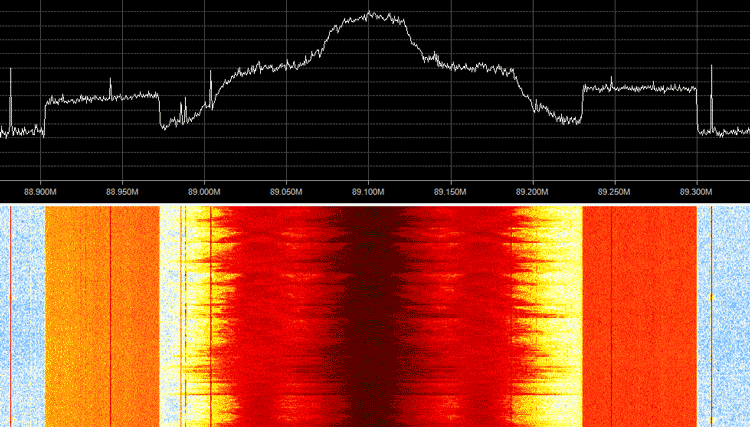
HD Radio is a high definition terrestrial digital broadcast signal that is only used in North America. It is easily recognized by the two rectangular blocks on either side of a broadcast FM station signal on a spectrum analyzer/waterfall display. Since HD Radio uses a proprietary protocol, finding a way to decode it has been difficult and so this signal has been inaccessible to SDR users for a long time. Back in February of this year we posted about Phil Burrs attempt, where he was able to create a partial implementation (up to layer 2) of the HD Radio standard, but didn’t get far enough to decode any audio in layer 3.
However, now cyber security researcher ‘Theori’ has created a full RTL-SDR based decoder for the HD Radio protocol. In his post Theori explains that the HD Radio system is split into three layers. Layer 1 finds the signals and does decoding and error correction. Layer 2 is a multiplexing layer, which allows various layer 3 applications to share the bandwidth. Layer 3 is the audio data layer. In his post he explains how these layers work in detail.
One of the main findings was the discovery of the audio compression codec. Theori found that the codec was essentially HE-AAC with some minor modifications. The modifications were minor enough that he was able to adapt the open source FAAD2 library for HD Radio audio decoding.
Theori’s code is open source and available on GitHub. The code includes the patch to modify FAAD2 for HD Radio and it is automatically applied during the build. A sample file for testing the decoder is also provided and we tested the decoder with the sample and it worked well. The decoding can also be performed in real time and examples of that are also on the git readme.
This paper describes a new method for the synchronisation of multiple low-cost open source software-defined radios (SDR). This solution enables the use of low-cost SDRs in interesting navigation applications, such as hybrid positioning algorithms, interference localisation, and cooperative positioning among others. Time synchronisation is achieved thanks to a time pulse that can be generated either by one of the SDRs or by an external source, such as a GNSS receiver providing 1PPS signal. Experimental results show that the proposed method effectively reduces the synchronisation offset between multiple SDRs, to less than one sampling period.
In simple terms, hybrid positioning is the process of using multiple signals such as WiFi, Bluetooth and cell phone signals etc together to get an accurate position of the receiver. By using several sources localization accuracy can be improved, but to do this each receiver much be precisely synchronized to the same clock source.
The system they created uses a 1PPS GNSS based time source connected to the SYNC_IN inputs on both HackRFs. The synchronization code is run in hardware on the HackRF’s onboard CPLD (complex programmable logic device). Furthermore they also write the following regarding the system and code which has been adopted into the HackRF repository:
A new time synchronization feature has been recently adopted in the HackRF official repository thanks to the collaboration between SPCOMNAV group, Università di Bologna, and the European Space Agency (ESA).
This contribution allows any user to precisely synchronize multiple HackRF devices below 50 ns, by means of a minor hardware modification and the firmware update.
More information about the driver updates and instructions for use can be found in this Git pull request. The team also write that their work was presented at the NAVITEC 2016 conference.
HackRF Synchronization with a 1PPS GNSS Reference.
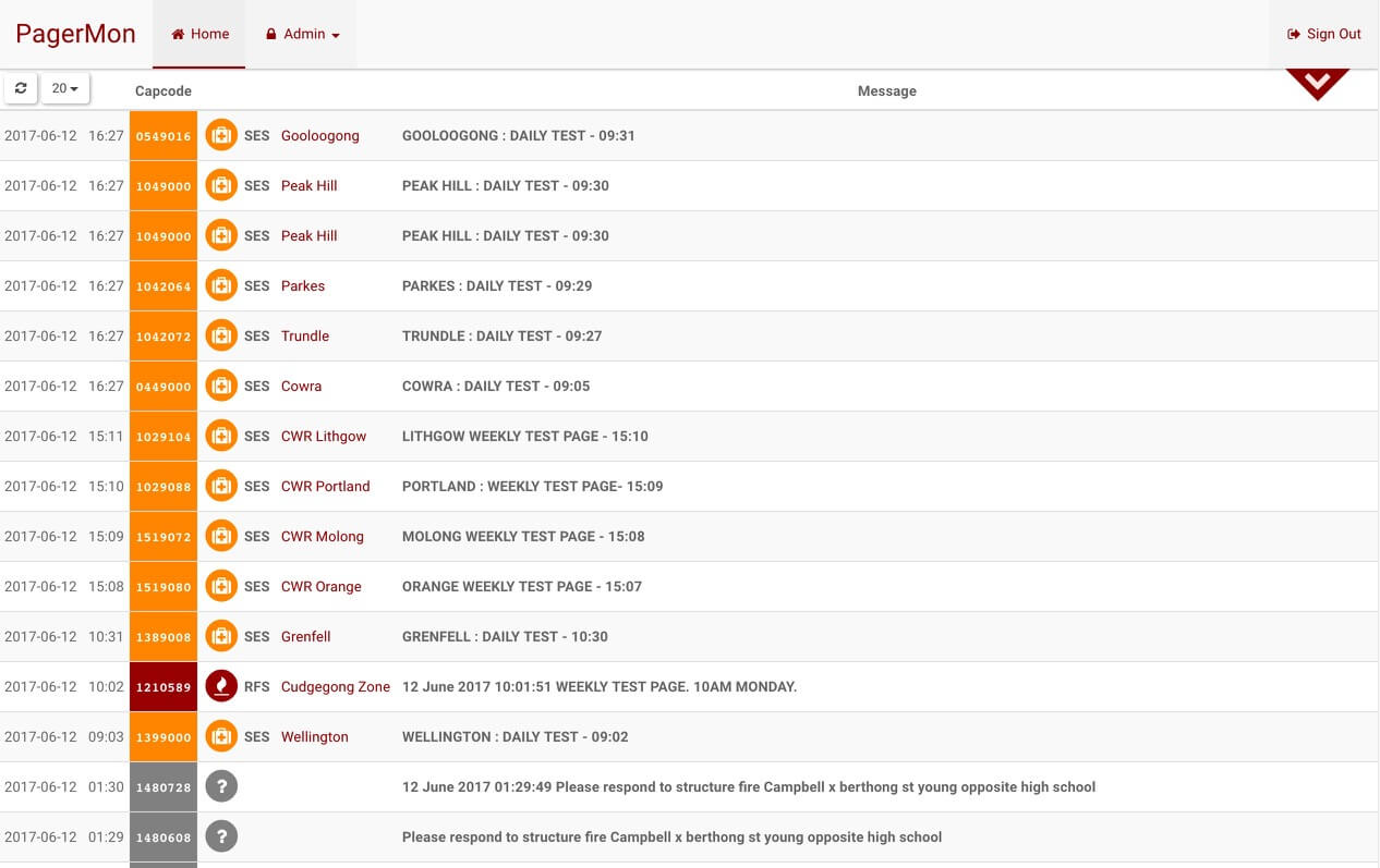
Thank you to Dave for submitting information about his new pager message display software called PagerMon. PagerMon is a web browser based tool for displaying POCSAG pager messages decoded by multimon-ng. It is based around nodejs and uses a sqlite database for storing the messages. Multimon-ng is an RTL-SDR compatible digital mode decoder which can decode multiple protocols including POCSAG pagers.
PagerMon and the features and future features are listed below:
PagerMon is an API driven client/server framework for parsing and displaying pager messages from multimon-ng.
It is built around POCSAG messages, but should easily support other message types as required.
The UI is built around a Node/Express/Angular/Bootstrap stack, while the client scripts are Node scripts that receive piped input.
Features
Capcode aliasing with colors and FontAwesome icons
API driven extensible architecture
Single user, multiple API keys
SQLite database backing
Configurable via UI
Pagination and searching
Filtering by capcode or agency
Duplicate message filtering
Keyword highlighting
WebSockets support – messages are delivered to clients in near realtime
Pretty HTML5
May or may not contain cute puppies
Planned Features
Multi-user support
Other database support (MongoDB and DynamoDB planned)
Horizontal scaling
Enhanced message filtering
Bootstrap 4 + Angular 2 support
Enhanced alias control
Graphing
Push notifications
Non-sucky documentation
The GitHub readme has a getting started section which shows how to set up the server and get it running on your local machine.
Over on YouTube user Kevin Loughin has uploaded a video demonstrating his SDRplay RSP2 running on a Raspberry Pi 3. The software he uses is CubicSDR which is a multiplatform program that is similar to software like SDRUno, SDR#, SDR-Console, HDSDR etc. The video shows CubicSDR running, but the interface is quite slow and laggy, although the audio is at least not choppy.
In a previous post we showed one of Kevin’s earlier videos where he does a tutorial and some scripts that help to actually set up the SDRplay drivers and CubicSDR in Linux. In the new video he first goes over a specific hack that needs to be done in Raspbian to fix the PulseAudio server. Then he explains that you can run the Linux build script mentioned in his previous tutorial video and it should work on the Raspberry Pi 3 just fine. Finally he mentions that CubicSDR and the SDRplay use a high amount of CPU processing on the pi3 so some sort of cooling mechanism is required or the pi3 may throttle down its CPU.
Ham Radio - SDRPlay running with CubicSDR on a raspberry Pi 3
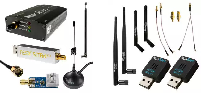
The first prize is a NESDR SMArt XTR HF Bundle. The NESDR SMArt XTR is an E4000 unit with SMA connector in the SMArt form factor. E4000 dongles have a higher maximum frequency range of up to 2.3 GHz, but a lower frequency minimum of 64 MHz. However, generally the R820T2 chip has better RF performance. The prize bundle comes with a ham-it-up upconverter, a balun 1:9, and some whip antennas.
The second prize is a NESDR Nano 2+ ADS-B bundle. The Nano 2+ is a small 1 cm x 1 cm dongle which is often used for Android mobile devices, or computing hardware like Raspberry Pi’s. The bundle comes with 1090 and 978 MHz whip antennas and some adapters.
Third prize is the same as the second prize, but with a Nano 2. The difference between the Nano 2 and Nano 2+ is that the Nano 2 does not have a TCXO. The fourth, fifth and sixth prizes are individual dongles.
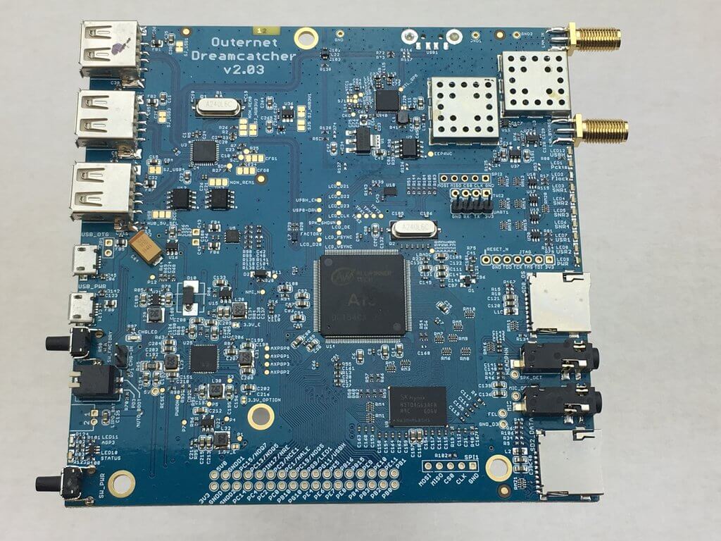
Recently Outernet released their new ‘Dreamcatcher’ hardware which is an RTL-SDR + L-band LNA & filter + computing board all on the same PCB. The Dreamcatcher costs $99 USD and can be bought directly from their store. For your $99 you get the Dreamcatcher board, as well as a new ceramic L-band patch antenna which has a built in L-band LNA and filter. The built in LNA is useful as it allows you to use a few meters of extension cable in order to get the patch antenna in a good position outdoors.
At the moment the Dreamcatcher can be run with two different SD card images: the Skylark Outernet software, or Armbian (Linux). The Armbian image is basically just standard Armbian and at the moment does not actually run any Outernet software, and cannot decode their signal – but this is being worked on. Eventually they hope to depreciate the Skylark image and instead use an Outernet receiver app that runs on Armbian.
When running on the standard Armbian image, the Dreamcatcher can be used as a regular RTL-SDR connected to Linux, as there is a bypass port which bypasses the built in L-band LNA and filter. This port is enabled by default, but can be software switched to the L-band port if desired. There is also a 4.8V bias tee on the bypass port that can be turned on in software and used to power external devices via the coax cable. Currently there is no display support on the Dreamcatcher so the unit must be run headless, meaning that you must connect to it via UART or SSH from another PC.
The Outernet Dreamcatcher
The Dreamcatcher is advertised with the following specifications:
L-band SAW filter (1525 – 1559 MHz)
Two-stage L-band LNA with 34dB gain
1 PPM TCXO
RF bypass for tuning from 24 – 1600 MHz – use as a regular RTL SDR!
Software switchable bias tee
3 USB ports
GPIO forest
UARTs, I2C, SPI headers (unpopulated) for driving external hardware
Two microSD card holders – for boot and storage!
1 GHz CPU
512 MB RAM
USB wifi dongle (based on RTL8188CUS chipset) – AP mode capable!
Lots of LEDs!
Switches!
microUSB OTG
microUSB power port
Audio In/Out
Fully mainline (4.10) kernel and Uboot (2017.01) support!
Also as explained on the forums, Dreamcatcher uses an Allwinner A13 SoC, which has inside an ARM Cortex A8 @ 1 GHz CPU. They’ve also added 512MB of RAM. The PCB measures 12 cm x 12 cm.
Currently the Dreamcatcher is being advertised as beta hardware, as they give the following warning:
Although some assistance can be found on our forums, Outernet provides no direct support for this product. If you are not a tinkerer, hobbyist, or hardware hacker, you may be disappointed with your purchase.
The Dreamcatcher also comes with Outernet’s latest L-band patch antenna. The new patch antenna uses a ceramic patch and a 12 cm x 12 cm PCB ground plane. The antenna is ‘active’, as it has a built in L-band LNA and filtering. It is powered by the bias tee on the Dreamcatcher, and can also be powered by the bias tee on our V3 RTL-SDR’s. An active antenna is a good idea as this allows you to place the antenna outdoors (you’d need to waterproof this antenna in a plastic box though), and run a coax cable inside. The LNA should help overcome the coax cable loss which can be quite high at the L-band Outernet frequency of 1.5 GHz.
Outernet has provided us with a sample of this kit, and we plan to release a full review of the unit within the next few weeks.
Outernet active ceramic patch antenna (Front)Outernet active ceramic patch antenna (Rear)
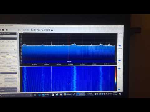
Over on his YouTube channel GusGorman402 has uploaded a tutorial which shows how he monitors ATCS (Advanced Train Control System) signals from trains. ATCS signals are found in the USA, and is used for things like communications between trains, rail configuration data, train location data, speed enforcement, fuel monitoring, train diagnostics and general instructions and messages.
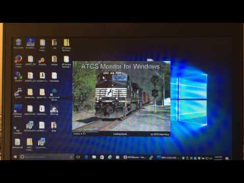
In the video he first shows how to determine the frequency of trains signals in your area by using the US FCC database. He then shows how to download and install the ATCSMonitor software which is used for decoding the signals, and then walks us through configuring the correct settings within the software. The train signal audio is piped from SDR# to ATCSMonitor via VBCable, and received with an RTL-SDR and simple whip antenna.
Later in the video he shows how to fully set up the software with train databases so that the actual spotted train names show up. He also shows how to set up the dispatcher display which visually shows the current train locations and track configurations.
GusGorman402 has uploaded the tutorial in two videos. The first shows the full tutorial, configuration and demo for trains in the BNSF fleet. The second video shows how to monitor the Union Pacific fleet which uses a different protocol, which requires a slightly different set up in ATCSMonitor.