Beta testing a modified RTL-SDR Driver for L-band heat issues

The R820T/2 RTL-SDR’s are known to have a problem that surfaces when trying to listen at L-band frequencies above about 1.5 GHz. As the dongle heats up the internal PLL appears to loose lock, causing reception to be lost above a certain frequency which is usually above around 1.5 GHz. There appears to be manufacturing variation between R820T/2 chips, so some dongles may exhibit this problem, whilst others do not, and some may fail at lower or higher frequencies than others.

This problem can be almost completely solved by cooling the RTL-SDR, and this is the reason we have added a thermal pad to the RTL-SDR dongles sold by us to aid with passive cooling via the metal case. In our tests this solves the problem for almost all dongles, but a few still do sometimes still exhibit this problem after running for a few hours.

Recently we were informed by a reader of RTL-SDR.com about a conversation on IRC where some users suggested modifying the RTL-SDR drivers to solve this problem. The suggestion was to modify the VCO current settings so that they were implemented in the same way as in the Airspy (which also uses the R820T2 but does not have this problem). Basically, in the Airspy the current is set at maximum on initialization, whereas in the RTL-SDR drivers it is set lower, and then bumped up if the PLL fails to lock. Setting it to maximum in the first place seems to help stop signal loss at L-band frequencies.

So far we’ve tested this change with a dongle that was known to be very bad at L-band. This dongle used to fail at 1.65 GHz after 20 seconds. With the driver change it fails after 2 minutes which is an improvement. With passive cooling via thermal pad and our metal case it used to fail after 15 minutes or so, but with passive cooling and the driver change it runs indefinitely.

If you’re having problems at L-band and would like to test this change then we’ve uploaded a modified Windows version of the driver on GitHub here https://github.com/rtlsdrblog/rtl-sdr/releases. It is based on Keenerds version of the RTL-SDR drivers. Simply download the .dll file and replace the current version in your SDR# folder, or other folder. Let us know if it helps you. 

The main change made is r82xx_write_reg_mask(priv, 0x12, 0x00, 0xe0); is added to the init code, and r82xx_write_reg_mask(priv, 0x12, 0x80, 0xe0); r82xx_write_reg_mask(priv, 0x12, 0x60, 0xe0); are removed from the set_pll and pll check code.

Thanks to patchvonbraun, Youssef of Airspy and others on IRC for discussing this problem.
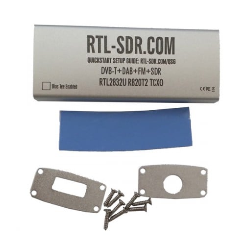
case_only
Passive cooling via thermal pad and metal case heatsinking resolves the L-band problem in most cases.


RTLSDR4Everyone: Testing the Nooelec and RTL-SDR Blog Metal Cases

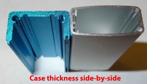
Over on his blog rtlsdr4everyone, author Akos has been testing the metal cases produced by Nooelec and RTL-SDR Blog (this site!). In his post Akos compares the Nooelec aluminium enclosures for the MCX based RTL-SDR dongles and for the ham-it-up upconverter, and also our aluminium enclosure for our SMA RTL-SDR dongles.

In his post Akos discusses the pricing, size, durability, heatsinking, shielding, and various other aspects of the cases. He also does a toughness test where he runs over each case with a car – all cases pass the test.

We’d like to add that all our dongles now come with an aluminium enclosure standard, but if you have one of our older models you can upgrade to the aluminium case for $4.95 including shipping from China. Akos writes that our cases can also potentially be used with other (non-SMA) RTL-SDR dongles too with a few modifications. Also the heatsink Akos adds to the cases is probably a bit of an overkill as in our tests our metal case with thermal interface pad is enough to almost completely solve heat related issues at L-band frequencies. Adding a small additional heatsink should be sufficient if there are still problems.

Case thickness comparison.

Akos also adds that he has updated his review of the Balun one nine with a YouTube video showing the difference in reception between a long wire antenna with and without the balun used.

Listening to an Astronaut Transmitting from the International Space Station

Over on YouTube user surfrockuk shows a fun and educational use of the RTL-SDR. Every now and then astronauts will arrange a ham radio session where they will communicate with a school. An RTL-SDR can be used to listen in on at least the downlink (astronaut talking) portion of these transmissions. 

The following video shows astronaut Tim Peake transmitting from the international space station (ISS) on Feburary 19th 2016. He was speaking to Oasis Academy in the UK. To receive the signal surfrockuk used an RTL-SDR with a QFH antenna. Many people have reported that other simple antennas such as discones, quartwave ground planes and even long wire antennas have been good enough to receive transmissions from the ISS too.

Other transmissions that can be received from the ISS include SSTV, space walk communications, and in the future DATV.

Tim Peake Transmitting from the International Space Station - 19th February 2016

Building a Direction Finding System with a Frequency Mixer and SDR

David of rowetel.com has recently been working on creating a direction finding system with his HackRF. A direction finder can be used to determine which direction a radio signal is coming from and is good for detecting sources of noise, illegal transmissions, for amateur radio fox hunts or for in David’s case, tracking down a local repeater troll.

In most direction finding implementations so far people have ran two SDRs from the same clock source in order to create a phase coherent receiver. However David is using a different method and he writes: 

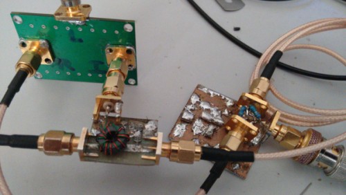
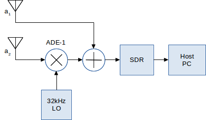
The trick is to get signals from two antennas into the SDR, in such a way that the phase difference can be measured. One approach is to phase lock two or more SDRs. My approach is to frequency shift the a2 signal, which is then summed with a1 and sent to the SDR. I used a Minicircuits ADE-1 mixer (left) and home made hybrid combiner (centre).

Direction finding hardware.
Direction finding block overview.

David uses his HackRF to capture the signal and the free Octave numerical computation environment to compute the mathematics. In his post David explains the math behind this implementation, and shows some of his results in which he has been able to find the angle towards the transmitter in a test bench set up.

David also writes that this method could be used for offline direction finding. By logging the baseband signal whenever a transmission occurs, direction finding could be done days later and compared with several logged transmissions across town to get a cross bearing. He also writes that an offline logging system would be useful for evidence in case of prosecution of people illegally transmitting.

Hacking Alarm Systems with an RTL-SDR and RFcat

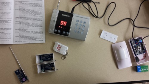
Back in 2014 the author of boredhackerblog.blogspot.com did a final year project for his wireless security class on hacking home alarm systems. His presentation was titled “How we broke into your house”. In his research the author used both an RTL-SDR and a simple RFcat wireless transmitter and performs a simple replay attack on a cheap $50 alarm system. His process for reverse engineering the alarm was essentially:

  1. Look up the device frequency and listen to it with an RTL-SDR and SDR#.
  2. Record the signal and visually study the waveform in Audacity.
  3. Look up system part info and determine encoding type (e.g. ASK/OOK)
  4. Determine the bit string and baud rate.
  5. Program the RFcat to send the same disarm binary string.

Once again research like this shows that cheap home alarm systems have literally zero protections against wireless attacks. In a previous post we also showed how the popular Simplisafe wireless alarm system could be disarmed in a somewhat similar way.

$50 home alarm system broken by an RTL-SDR and RFcat.

RTLSDR4Everyone: Review of the Nooelec Ham-It-Up V1.3 and Balun 1:9

Over on his blog rtlsdr4everyone, Akos has posted two new reviews. One post reviews the latest ham-it-up v.13 upconverter and the other reviews the “Balun 1:9” impedance transformer.

An upconverter allows you to receive HF frequencies (0-30 MHz) with an RTL-SDR which has a lower frequency limit of 24 MHz.  The ham-it-up upconverter was one of the first upconverters to go on the market that targeted users of the popular RTL-SDR dongle. Over the years the ham-it-up has slowly been revised and now it is up at version 1.3. The biggest changes in the latest version are a revised design that uses the ADE-1 in reverse (better VLF operation), a presoldered oscillator and it also now includes the previously optional noise source by default. 

In his review Akos compares the ham-it-up v1.3 to the older v1.2 model. His results show that the revised design seems to have better immunity to noise and better FM broadcast filtering. He also tests out the new battery power via connection and shows that using battery power is less noisy.

Previously we posted a review comparing the ham-it-up v1.0, SpyVerter and Nobu’s Japanese upconverter. Although the ham-it-up v1.3 is much improved and we have not tested it, we still believe the SpyVerter is the better upconverter choice at the moment due to its better architectural design and included metal case, though Akos does point out that the ham-it-up is currently about $15 USD cheaper and has a passthrough switch.

Ham-it-up v1.3 vs ham-it-up v1.2

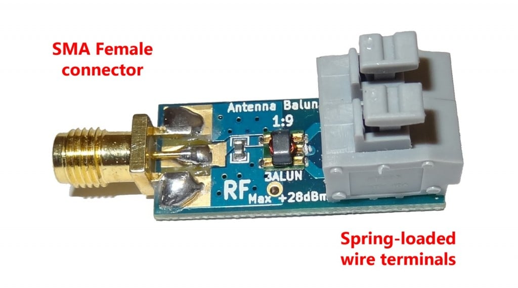
In his second post Akos reviews the Balun 1:9 which is a $10 balun that is designed for attaching a long wire antenna to the ham-it-up. The goal of the balun 1:9 is to transform the high impedance long wire antenna down to around 50/75 Ohms for the receiver. In Akos’ results he writes that he mostly see’s identical or better performance with the balun connected.

The Nooelec balun 1:9

To add to Akos’ review, we want to note that we think that there might be some confusion over baluns and ununs. We wonder if a 9:1 unun (instead of a balun) should be used for a long wire antenna, since a long wire is an unbalanced antenna. We think a balun should be used for a balanced antenna such as a dipole. In his review Akos also found that connecting two longwire antennas to the spring terminals improved reception. This may have possibly been because adding two longwires essentially created a balanced dipole antenna. To implement a longwire antenna unun with a balun, we think that the second terminal and coax shield should be connected to a good ground source like a cold water pipe. If you have knowledge on this topic please comment to confirm or expand on our theory.

FlightBox: Commercial RTL-SDR Based ADS-B (1090ES & 978UAT) Receiver for Pilots

For some time now, small aircraft pilots who don’t have access to expensive ~$1000+ ADS-B gear have been successfully using an RTL-SDR and Raspberry Pi combination to receive ADS-B and UAT to display aircraft and weather data on an iPad. The first time we posted about this was back in August 2015.

The full implementation uses two RTL-SDR dongles to receive both 1090ES aircraft position information and 978 UAT to receive weather radar information. Both dongles are used on a Raspberry Pi mini computer that runs a program called Statrux. Stratux takes the ADS-B information received by the RTL-SDR’s and re-transmits the data out via WiFi. Then an iPad running special pilot navigation aid software such as ForeFlight can interface with the WiFi signal and receive the ADS-B and weather information.

Assembly of a Stratux box requires the purchase of each individual component or a Raspberry Pi kit that includes the stratux software image on an SD card, RTL-SDR and WiFi adapter. However, setting up a Stratux box may be a little difficult for pilots who do not have any electronics DIY skills.

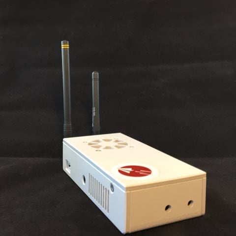
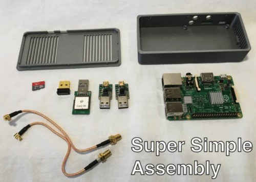
To solve this, a new product called FlightBox recently ran a successful Kickstarter campaign. FlightBox provides a ruggedized plastic case, a Raspberry Pi 2 preloaded with software, two nano RTL-SDR dongles, two pigtail adapters, a 10Hz WAAS GPS module, and two customized ADS-B whip antennas (one for 978 MHz and one for 1090 MHz).

The FlightBox costs $200 for single band operation and $250 for dual band (1090ES and 978UAT). They are currently accepting pre-orders for delivery in late March/April.

For more information about Stratux see the active discussion forum at reddit.com/r/stratux.

The FlightBox: An RTL-SDR based ADS-B 1090ES and 978UAT receiver for Pilots.
Components used in the FlightBox, including two RTL-SDR dongles.
Components used in the FlightBox, including two nano RTL-SDR dongles.

YouTube video showing Inmarsat C-Band AERO Reception

Last week we posted how programmer Jonti had successfully implemented a C-Band AERO decoder into his JAERO software. C-band AERO signals are the earth downlink portion of AERO. Planes transmit data upwards towards the satellites and then the Inmarsat C-band transmitter re-transmits the information back to a basestation on earth. This is different to the L-band AERO signals which are signals transmitted from the satellites to the aircraft. C-band signals are interesting because they contain plane position info, and so can be used to track aircraft much like what is done with ADS-B reception, but over a much larger area. However, C-Band signals are much more difficult to receive as they are at 3.616 GHz and require a 1.8m or larger satellite dish.

Over on YouTube user AceBlaggard has uploaded a video showing an example of C-Band signals being received with an Airspy SDR and being decoded with the new version of JAERO. About the hardware used AceBlaggard writes:

Hardware is a 1.8M PF dish and Titanium Satellite C1 PLL LNB feeding a Prof-Tuner 7301 sat card which loops out to an Airspy SDR.

Inmarsat C Band aero feed.