MultiPSK is a signals decoding program with many available decoders to choose from. It is also able to directly connect to the RTL-SDR, or be used via a virtual audio cable. The latest beta version (available on the MultiPSK Yahoo mailing list) now allows for decoding of Orbcomm satellites which transmit at around 137 MHz. While it is not possible to decode the encrypted messages, it is still possible to decode pieces of telemetry data from the satellites. MultiPSK writes the following information about Orbcomm:
This system has been developed by the ORBCOMM society which disposes of a constellation of about 28 active LEO (“Low Earth Orbit”) satellites, transmitting between 137.2 and 137.8 MHz (+/- 2.5 KHz maximum of Doppler shift).
This system permits:
to handle messages (encrypted) from ground users (ships, trucks, oil wells…) until other ground users, through the ORBCOMM satellites, the cover being worldwide. These frames are decoded by Multipsk but not deciphered.
to broadcast identification, frequencies, position and orbital elements pieces of information, not encrypted. These frames are decoded and interpreted by Multipsk.
This mode is available for licencied copies, only (otherwise, the decoding is stopped after 5 minutes).
One user of MultiPSK has uploaded a video showing the Orbcomm decoding in action.
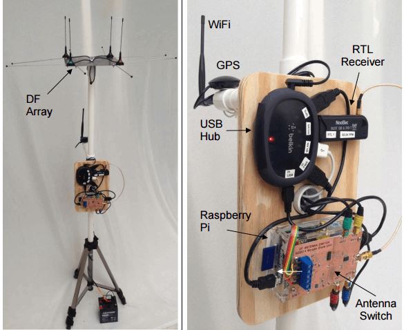
Something we missed posting about from last year was this presentation on “RasHAWK”, a direction finding system (pdf) built out of a Raspberry Pi, an RTL-SDR and four antennas on a 4 way switch running software created with REDHAWK. REDHAWK is a visual DSP development platform that can be considered similar to GNU Radio or some parts of MATLAB. The authors write:
The RasHAWK team has used a Raspberry Pi as the basis for a networked RF sensor capable of supporting spectrum monitoring, signal intercept and direction finding (DF) operations.
Several RasHAWK sensors are deployed in a distributed sensor grid, wirelessly tethered to a command and control (C2) laptop. The system has the following key features and capabilities:
A simple operator interface to configure the sensors
Falling raster and PSD displays to monitor the spectrum for signal activity
Demodulate FM signals from target FRS radios and play audio on selected channels
Perform coarse DF on target emitters
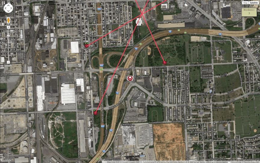
Display a map of the surrounding terrain that is annotated with the positions of the sensors, the target emitter and calculated lines of bearing (LOB) to the target. The map provides a RF Common Operating Picture (COP) with can be viewed on WiFi enabled tablets or smartphones.
Each RawHAWK sensor can determine the bearing of transmitted signal. By combining several networked RasHAWK sensors at different locations they are able to pinpoint the actual location of the transmitter on a map.
The RasHAWK system.Lines of bearings combined from three different RawHAWK sensors.
The SDRplay team have recently released a major update to their API and drivers. The new version is 1.8.0 and they write that it should remove the DC offset, reduce in band images from strong signals, and lower the noise floor. The SDRplay is a software defined receiver that costs $149 USD. They write:
We are pleased to announce release 1.8.0 of the API for the RSP. This is a major upgrade to the API with new features and an improved gain map which should result in improved performance over a key portion of the gain control range. Currently this API is available for Windows only, but versions for Linux and Mac OS and Android will follow shortly.
The API now incorporates automatic post tuner DC offset correction and I/Q compensation. This will almost completely eliminate the DC centre spike that was previously present in zero IF mode and also correct for amplitude and phase errors in the I/Q signal paths that can lead to in-band images when strong signals are present.
There is a new gain map for the RSP which should help improve the receiver noise floor for gain reduction settings in the range of 59-78 dB. To achieve this, the IF gain control range has been increased from 59 to 78 dB. In addition, the user can now turn the LNA on or off at any point within the IF gain control range. This means that the LNA can remain on for gain reduction settings of up to 78 dB, whereas previously the maximum gain reduction that could be attained whilst the LNA was on was only 59 dB. Being able to leave the LNA on will result in improvements in the receiver noise performance for gain reductions in the range of 59 to 78 dB. The upper 19 dB of the IF gain control range have now been disabled. In practice this part of the gain control range was useless as trying to operate within this region always lead to receiver overload even when signals were very weak.
To fully exploit the features of this new API release, we have also issued release 3.5 of the ExtIO plugin. This plugin will work with HDSDR, SDR sharp (releases 1361 or earlier) and Studio 1. Automatic I/Q compensation and DC offset correction will work with later versions of SDR sharp, but we will need to update the native plugin for users of these later versions to be access the new gain map.
Similarly, users of SDR Console will gain the benefit of automatic DC offset compensation and I/Q correction, but will not yet be able to access the new gain map. We hope that a version of SDR console that unlocks this feature will become available in the near future.
Until a new release of SDR-Console is available, you can copy the API into the SDR-Console installation directory…
from C:\Program Files\MiricsSDR\API\x64\mir_sdr_api.dll to C:\Program Files\SDR-RADIO-PRO.com\mir_sdr_api.dll
The API installer has also contains an extra certificate to be more user friendly for Windows XP, Vista and Windows 7 users.
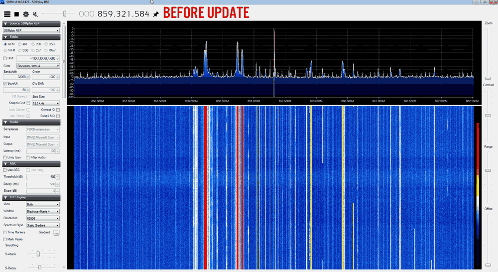
As they write that in band images from strong signals are reduced in this version we decided to do a quick before and after test using our own RSP receiver. We tuned into some TETRA signals that had exhibited images in the past on our RSP (you can see them as the yellow signals in the before image). In the new driver the images are completely gone.
Back on Dec 5 we posted about some Defcon 23 talks that were released from the Wireless Village set of talks. Recently some more talks from other tracks have been released and one of interest to our blog is the talk by Ian Kline titled “LTE Recon and Tracking with RTLSDR”. The talk’s blurb reads:
Since RTLSDR became a consumer grade RX device, numerous talks and open source tools enabled the community to monitor airplanes, ships, and cars… but come on, what we really want to track are cell phones. If you know how to run cmake and have $50 to pick up an RTLSDR-E4000, I’ll make sure you walk out of here with the power to monitor LTE devices around you on a slick Kibana4 dashboard. You’ll also get a primer on geolocating the devices if you’ve got a second E4000 and some basic soldering skills.
DEF CON 23 - Ian Kline - LTE Recon and Tracking with RTLSDR
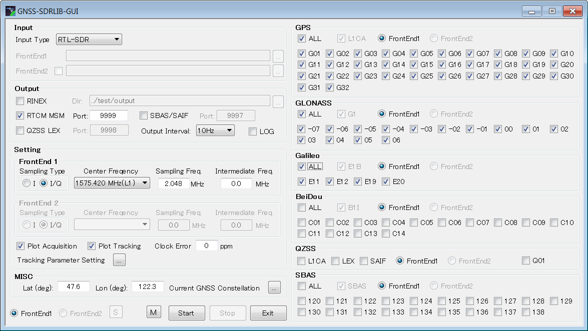
To receive GPS e.p. uses one of our RTL-SDR blog units (back in stock soon!) with the bias tee enabled which is used to power a cheap 5V active GPS antenna. For software he uses GNSS-SDRLIB and RTKLIB which runs on Windows. Using the RTL-SDR, GPS antenna and the decoding software he was able to get his current position to within about 5 meters of accuracy.
In his blog post e.p. shows a step by step guide on how to install and use the Windows software. In later posts he also shows how to install and use another program called GNSS-SDR which runs in Linux and can also be used to acquire GPS fixes with an RTL-SDR dongle.
The GNSS-SDRLIB GUI setup screen.
To illustrate the software in action e.p. has also uploaded a video to YouTube which is shown below.
SvxLink is an EchoLink and general purpose voice services system for controlling ham radio repeaters. A repeater is a radio tower that receives a weak transmission from a handheld or remote radio and then repeats the same message with greater power over a wide area. With repeaters radio communications can cover a much further distance.
Ham radio enthusiasts often set up repeaters for their own frequencies, so that they can be heard over a wider range. To control the repeater software like SvxLink is required. In the latest software update of SvxLink they added RTL-SDR support. They write:
The biggest news in this release is the support for RTL2832U based DVB-T USB dongles. This make it possible to use such USB dongles as cheap SDR (Software Defined Radio) receivers. This will open up the world of cheap receiver hardware to all SvxLink users. It will for example be very cheap to set up an extra receiver with local coverage for a SvxLink based repeater, as long as there is a network connection to the repeater. The modulation forms supported are: FM, FM narrow, AM, AM narrow, USB, LSB, CW, CW wide and wideband FM (broadcast). Running multiple receivers on the same dongle is supported as well as using multiple dongles.
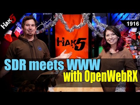
On this episode of Hak5 (a popular hacking and security themed YouTube channel) Darren and Shannon discuss OpenWebRX, a SDR web broadcasting and remote control tool that is compatible with the RTL-SDR. OpenWebRX is similar to the WebSDR software in that it allows people to connect to remote SDR’s on the internet and tune them to any station within their currently set bandwidth frequency range. Many already functioning online OpenWebRX receivers can be found in the database at sdr.hu.
In the first part of the video the Hak5 team explore the worldwide SDR’s on the sdr.hu website. Then in the second part they show a demonstration on how to install the OpenWebRX software in order to create a SDR broadcast with an RTL-SDR.
FREE SDR receivers all around the world with OpenWebRX - Hak5 1916
Radio transmissions between 0 - 30 MHz can travel all the way around the world. At these frequencies many interesting signals such as international shortwave radio, ham radio communications and several military transmissions exist.
The RTL-SDR's lowest tunable frequency is 24 MHz, and so it can only receive a small portion of the interesting transmissions that occur between 0 - 30 MHz. In order to listen to frequencies below 24 MHz an upconverter is required (either that or perform the direct sampling mod). An upconverter works simply by shifting these lower frequencies up to a higher frequency that the RTL-SDR can receive. For example, a 5 MHz signal might be upconverted to 105 MHz.
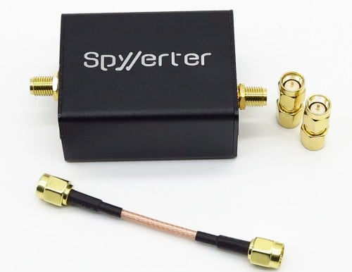
To date, most decent upconverters (such as the popular ham-it-up upconverter) have been based on the double balanced mixer architecture implemented by the ADE-1 mixer chip from Minicircuits. The SpyVerter on the other hand is based on a different type of architecture which is inspired by the H-mode mixer design that was used in the unreleased HF7070 communications receiver. The expected major advantage that this design has over a ADE-1 based design is better IIP3 performance. This essentially means that strong signals will not cause overloading issues in the SpyVerter, meaning less noise and spurious images.
Another advantage of the SpyVerter is its use of a 120 MHz low phase noise/low jitter clock, meaning less reciprocal mixing and thus greater SNR and a lower noise floor. A low phase noise clock is essential for getting good performance when receiving the very narrowband signals that are typically found between 0 - 30 MHz. The other upconverters do not specify their phase noise performance as far as we can tell.
The SpyVerter comes in a metal box, with three SMA adapters. A metal box is great because it helps keep strong interfering signals from entering the signal path, as well as stabilizing the internal temperature, keeping frequency drift to a minimum. Most upconverters only come with a metal box as a paid add on, but the SpyVerter comes in one by default.
Although the SpyVerter is designed to be used with the Airspy, it is fully compatible with the RTL-SDR as well. The SpyVerter can be powered via a USB cable, or via 5V bias tee (and this is compatible with the bias tee used on the RTL-SDR Blog units sold by us).