Tagged: rtl2832u

Replacing the Low Quality 28.8 MHz Oscillator on the RTL-SDR

The 28.8 MHz crystal oscillator on the RTL-SDR is known for being low quality. A low quality crystal means that the frequency tuning can be off by a few KHz and can cause the tuned frequency to drift over time.

In this article of the GBPPR ‘Zine (kindly mirrored by superkuh), the authors show a tutorial on how a cheap high quality 14.4 MHz temperature compensated crystal oscillator can be combined with a frequency doubler circuit to create a high quality 28.8 MHz clock source, which can then be used to replace the low quality oscillator on the RTL-SDR. A 14.4 MHz oscillator is used as high quality 28.8 MHz oscillators appear to be rare.

Frequency Doubler Circuit

Setting up an APRS iGate with the RTL-SDR

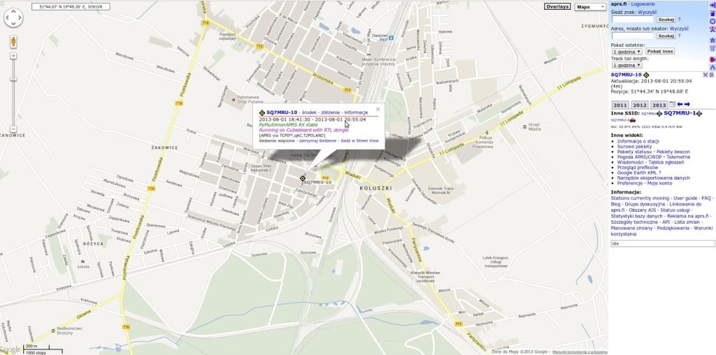
Over on Pawel Janowski’s blog (SQ7MRU) a writeup on how to set up an APRS iGate receiver with an RTL-SDR and cubieboard mini computer has been posted. The article has been written in Polish, but can be translated using Google Translate.

APRS stands for Automatic Packet Reporting System and is usually used by Amateur radio operators to broadcast the current GPS coordinates of something such as a transmitter site/car/boat or high altitude amateur balloon. These APRS packets are received by an iGate and then put onto the internet. Check out aprs.fi for an example.

To create an APRS iGate, Pawel runs a RTL-SDR compatible python program called pymultimonaprs which is used to receive and broadcast the APRS data on to the internet.

aprs_fi_rtlsdr

Video Comparison Between E4000, R820T, FC0013 and Comparison with SDR# and Linrad

On YouTube sm5bsz has uploaded a video showing a comparison between the E4000, R820T and FC0013 tuners, and also comparing the receive performance of SDRSharp and Linrad. In the video Linrad showed superior receive performance with the E4000 when compared to SDRSharp due to some custom gain profiles which are enabled in Linrad only (but can also be enabled in SDRSharp with a plugin/mod).

Note that the reason Linrad showed better performance is purely due to the fact that he used a modified librtlsdr driver in Linrad which has the custom gain profiles. However, in a previous post we posted about a modification/plugin to SDRSharp which allows this modified librtlsdr to be used, which will allow SDRSharp to perform as well as Linrad for the E4000.

Linrad is another software defined radio program which is much more difficult to use, but was the first program to support the modified librtlsdr. Some people prefer Linrad due to it’s advanced GUI which has a lot of signal information on display.

Software Defined Radio for Mariners: AIS Antenna Design Review

On a new blog called ‘Software Defined Radio for Mariners‘ aimed at mariners wanting to get into cheap software defined radio with the RTL-SDR, the author has posted an article for beginners on choosing a type of AIS antenna to build.

He reviews the performance of multiple homemade AIS antennas with his RTL-SDR, and finds that a Monopole antenna with two radials gave the best value/performance trade off.

He has also written a hardware guide article, explaining some of the most common antennas adapters and cable ends that might be found.

AIS Monopole Antenna

Version 5.0 of the CT1FFU Upconverter Now Available

Version 5 of the popular CT1FFU HF upconverter which is often used with the RTL-SDR and Funcube software defined radios has been made available for sale. A ready built and tested version 5 CT1FFU upconverter will cost you 55 Euros. See the circuit diagram and technical specs in this pdf file.

The upgrades include

– Smaller size PCB

– 4 new holes for screwing PCB

– MiniUSB connector

– 2 led 5V indication USB/ Phantom Power

– It runs with phantom power directly from Fun Cube Dongle’s SMA cable

– USB power for generic RTL TV dongle sticks

– Separeted antenna inputs HF/6m and VHF/UHF

– Automatic internal relay antenna switch: HF or Bypass VHF and UP

– WFM broadcast filter avoiding saturation of SDR front-end

– LED indication for converter running

– DBM diode ring mixer 7 dBm: This ensures exellent HF reception performance

– LO on 106.250 Mhz or 65.520Mhz: This avoids interference from WFM radios

– Tests made by hams worldwide reveal exceptional clean reception on HF

– Technical assistance after selling

– Either ready built and tested or as KIT easy to build by yourself

– Worldwide shipping and tracking is included in advertised price

– You can now choose the LO freq: 106.250Mhz or 65.520Mhz models

Exploring Unintentional Radio Emissions with the RTL-SDR

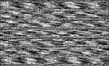
Melissa Elliot (0xABAD1DEA), an infosec security researcher has uploaded slides on the topic of investigating unintentional radio emissions from various electronic devices, and the security issues these emissions can cause. She used the RTL-SDR as the radio receiver to show that sophisticated equipment isn’t needed. One interesting experiment she performed was trying to recover a checkerboard image displayed on an LCD screen entirely via its unintentional radio emissions received with the RTL-SDR. She got close, as you can sort of make out the checkerboard pattern on the recovered image below. Update: Tomsguide have written an article on Melissa’s talk.

LCD Recover from Unintentional Radio Emissions

Measurements on RTL-SDR E4000 and R820T DVB-T Dongles: Image Rejection, Internal Signals, Sensitivity, Overload, 1dB Compression, Intermodulation

Over on the SDRSharp Yahoo group, HB9AJG has posted an interesting report in a PDF file containing some measurements (Note you will need to be a member of the group to download the file titled "Some Measurements on E4000 and R820 Tuners.pdf". Here is a Direct Mirror of the file.) quantifying the performance of both the E4000 and R820T RTL-SDR DVB-T dongles. See the discussion in the Yahoo group here.

These results confirm the feeling that many RTL-SDR users have had: that the E4000 is more sensitive in the lower frequencies, and that the R820T is more sensitive in the higher frequencies, which is why it is recommended for ADS-B. The results also show that the R820T is better in terms of Image Rejection and Internal Signal Birdies.

He comprehensively summarizes his results in the following

Image Rejection
Because the E4000 is a Direct Conversion Receiver, it has an Image Rejection problem. By switching on Correct IQ in SDR# a more or less acceptable 50dBs are reached. For the same reason, a "hump" shows in the center of the spectrum display. By using a well filtered external power supply (not from the USB connector) the hump might be reduced.
  
Internal signals
The E4000 shows many signals actually not present at its input ("birdies"). Birdies are easy to recognize: most of them (except the harmonics of the clock) vary their frequency when moving the spectrum window in frequency. Many of them even move up if you move the window down in frequency.

The R820 is much cleaner in this respect: besides the harmonics of the clock (28.8MHz) only few birdies show up.

Sensitivity
Both dongles have a very high sensitivity. Between about 50 and 450MHz the E4000 is about 5dB better than the R820 (-139dBm vs -134dBm). At 1000MHz the E4000 is about 8dB less sensitive (-129dBm vs -137dBm). No measurements could be made above 1040MHz.

Overload and 1dB Compression
If a signal is strong enough, it may cause overload, i.e. many (unwanted) signals show up on the spectrum display that are not present at the antenna input. Also, if we listen to a desired signal, another signal (if strong enough) may cause a reduction of the S/N ratio of the desired signal.

Both dongles have a digitally tuned RF filter after the preamplifier that (together with the following digital signal
processing) improves the overload/1dB compression limit considerably.

- The filter of the E4000 is about +/-0.8MHz wide, but less steep than the filter of the R820.
- The filter of the R820 is about +/-3MHz wide, but steeper than the filterof the E4000.

For the E4000 the overload/1dB compression limit is not linearly dependent of the gain set in Configuration of SDR#:
if the gain is reduced by 13/20/30dB, the overload limit is improved by only 7/14/25dB (measured on 145MHz only).

For the R820 the overload/1dB compression limit is quite linearly dependent of the gain set in Configuration of SDR#: if the gain is reduced by 11/20/30dB, the overload limit is improved by 12/20/30dB (measured at 145MHz only).

For both dongles it seems there is nothing to be gained from activating RTL AGC or Tuner AGC.

Intermodulation
Intermodulation products in general show up close to the overload/1dB compression limits. However, if the strong
signal is on the roll off of the filter, they appear well before this limit.

Aliasing
Aliasing always occurs if an insufficiently band limited signal is sampled, i.e. if the signal to be sampled contains frequencies above half the sampling frequency. Thus, aliasing is an effect showing up in many SDRs, not only in these dongles. In both types of dongles there is not much space for brick wall filters. Therefore, aliasing effects are well visible with both dongles.

What do we learn from these tests?

- Both types of dongles are very sensitive. The choice depends on which frequency range you are most interested in.

- Considering internal signals and image rejection, the R820 is much cleaner than the E4000.

- Set the spectrum display of SDRSharp to show a range of not more than 60db above the noise floor. If a signal is close to the top, you know you are close to overload.

- Both types of dongles are prone to overload by strong signals within their filter bandwidth: +/-0.8MHz for the E4000, +/-3MHz for the R820. Therefore, keep signals within this bandwidth to not more than about 60dB above the noise floor
by reducing the gain. If increasing the gain does not audibly increase the signal to noise ratio of the desired signal any more, reduce the gain by one step. Do not switch on RTL AGC or Tuner AGC, as it seems there is nothing to be gained.

- Outside their filter bandwidth both types of dongles can live with much higher signals without showing serious degradation. Use the gain control as explained above to check a possible reduction of signal to noise ratio of the desired signal or the appearance of "new" signals not present at the antenna
input.

- Intermodulation occurs if several strong signals are present within the bandwidth of the dongle. Their individual power adds up (add 3dB per equally strong signal). Therefore, in frequency bands with many strong signals, e.g. broadcast bands, the gain must be reduced even further. Watch for "new" signals appearing when increasing the gain, and then reduce the gain by one step.

- If very strong signals are present at the antenna input >-40dBm), they should be attenuated by bandstop or notch filters.

RTL-SDR Panadapter using RANVerter and Cheap Ham Radio

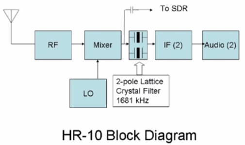
YouTube user ranickel and creator of the RANVerter HF upconverter for software defined radios has posted a video showing how to use an RTL-SDR dongle and RANVerter to create a panadapter for an old and cheap Heathkit HR-10 “beginners receiver” ham radio.

He connects the mixer stage of the HR-10 via a capacitor to his RANVerter which then connects to a RTL-SDR dongle.

RANVerter Panadapter

Cheap and Easy SDR Panadaptor for Older Receivers