Tagged: antenna

Review: FlightAware 1090 MHz ADS-B Antenna and Filter

In this post we will review the FlightAware ADS-B Antenna and their 1090 MHz band pass filter. The FlightAware ADS-B antenna is claimed to have 5.5 dBi of gain, a rugged weatherproof radome and N-type female connector. It costs $44.95 USD on Amazon for US customers and $54.95 USD on eBay for international customers (plus shipping). They write that they are selling this antenna at cost in order to improve FlightAware coverage.

The FlightAware ADS-B filter is a bandpass filter with a pass range of 980MHz - 1150MHz, ~1.5dB insertion loss and more than 40dB attenuation of unwanted frequencies. It costs $19.95 USD on Amazon for US customers and $24.99 USD on eBay for international customers (plus shipping). Generally it is much cheaper than other ADS-B filter options on the market.

FlightAware.com is a company that specializes in aggregating ADS-B data from contributors around the world. People can contribute by using the FlightAware official hardware, or with a simple SDR, like an RTL-SDR dongle. They display the data on their website as it can be used to help track flight arrival times. A similar company is flightradar24.com.

If you are interested in getting started with ADS-B reception with your RTL-SDR then we have a tutorial here.

FlightAware ADS-B Antenna

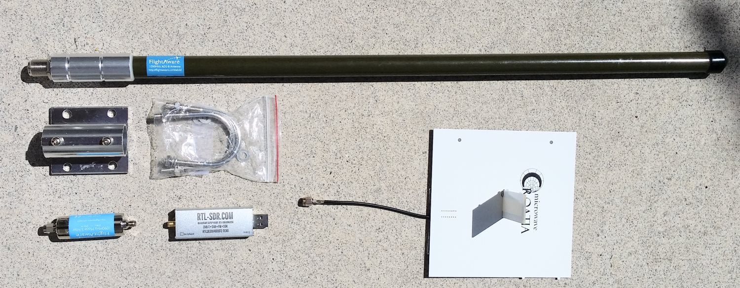
The FlightAware antenna is about 64cm in length and about 2cm in diameter. It uses an N female connector and comes included with mounting brackets and U-bolts. It is painted olive green.

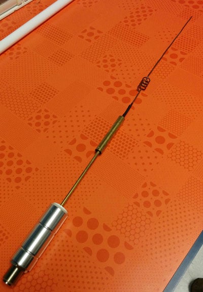
In the photo below we compare the size of the antenna against a reference monopole antenna, an RTL-SDR dongle and the FlightAware ADS-B filter. The antenna appears to be very solidly built and of a high quality finish. The antenna is wareproofed with some silicon caulking used around the seams of the endcaps.

Size comparison
Size comparison

The FlightAware ADS-B antenna is a collinear type antenna. Collinear antennas are omnidirectional (receives equally from all directions) and have a higher gain compared to most other omnidirectional antennas, but their radiation pattern is flattened and directed more towards the horizon. This is a good thing for receiving planes that are far away as they will be at lower elevations, but aircraft at higher elevations relative to your antenna may be received poorer. Although, it is likely that any aircraft at high elevations to your position will be closer to you anyway, and thus have a stronger signal making the reduced gain at higher elevations less important. Judging by it's ~60cm length and it's specified gain of 5.5dBi, the FlightAware antenna is likely to be a 4 element collinear.

A 4 element collinear generally has positive gain from 0 - 20 degrees of elevation, whereas a simple dipole or ground plane may have positive gain from between 0 - 40 degrees of elevation. A typical commercial jet flys at about 10km. At a distance of 100km this jet would be at a 5.7 degree elevation, and at 10km 45 degrees. Smaller aircraft fly at about 3km maximum, and at 100km would have an elevation of 1.7 degrees, and at 10km 16.7 degrees, so the collinear covers most cases.

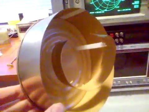
A reader wrote in to us to let us know that the internals of the FlightAware antenna had actually previously been posted in an old thread on their forums. From the image it looks like the antenna may be a sleeved dipole + whip + impedance matching design, or something similar. This design is somewhat of a collinear design thanks to the additional whip which also gives a flatter radiation pattern with more gain direction out towards the horizon. These antennas are omnidirectional (they receive equally from all directions) and have a higher gain compared to most other omnidirectional antennas, but their radiation pattern is flattened and directed more towards the horizon. This is a good thing for receiving planes that are far away as they will be at lower elevations, but aircraft at higher elevations relative to your antenna may be received poorer. Although, it is likely that any aircraft at high elevations to your position will be closer to you anyway, and thus have a stronger signal making the reduced gain at higher elevations less important.

The internals of the FlightAware antenna.

If you live in a valley, or have multiple obstacles such as trees or buildings blocking your view of the horizon then the higher gain design may work worse than a dipole/quarter wave ground plane/folded monopole type antenna. In this situation you'd mainly only be able to receive ADS-B signals from higher elevations, so an antenna with a less flat radiation pattern would work better. See the end of this post for some example radiation pattern diagrams.

Continue reading

Building a Wideband Helix Antenna for L/S/C Bands

Over on YouTube user Adam Alicajic (creator of the popular LNA4ALL low noise amplifier) has uploaded a video showing the performance of a home made wideband helix antenna that he has created for receiving signals such as ones from L-Band Inmarsat satellites. See our tutorial for more information on receiving Inmarsat signals.

Adams helix antenna is built out of an old used can and is based on a 1.1 turn design. In the first of three videos he shows that the SWR of the antenna is all well below 2.0 from 1.5 GHz to 3 GHz. In the second video Adam shows the performance of the helix antenna on actual L-band signals being received with an RTL-SDR dongle. In the final video Adam compares the helix again a patch antenna and finds that the two receive with very similar performance.

Wideband L/S/C band helix antenna Part.1

Wideband L/S/C band helix antenna Part.2

Wideband L/S/C band helix antenna Part.3

Improving Reception with the Stock RTL-SDR Antenna by Building a Corner Reflector

Last week a reader of RTL-SDR.com wrote into us to let us know about some experiments that he had been performing with the telescopic stock antennas provided in our RTL-SDR dongle packages. The reader had built a corner antenna reflector in order to improve reception in one direction. We are posting his write up and results below:

This tutorial will discuss the use of a Corner Reflector with a monopole antenna, i.e. the stock RTL-SDR antenna. To keep this tutorial concise, the reader is encouraged to study the Wikipedia pages for details about Corner Reflector Antennas, Dipoles and Monopoles.

Corner Reflector Antennas are very easily constructed from 2 A4-sized cardboard panels, covered with tinfoil. This allows for a foldable and transportable external reflector to the built-in wifi antennas of a laptop, which are located on the upper corners of the display. 

The reader is pointed to the fact that corner antennas are based on a Dipole, where the stock RTL-SDR antenna is a Monopole, so some adjustments will have to be made, which is discussed and explained later in this text. If there are real antenna specialists reading this, they are encouraged to do a more thorough writeup on the exact mechanism of a monopole-based corner reflector antenna, as there was little information to be found on the internet.

The experiment started as an attempt to receive a DVB-T signal centered around 506 MHz, from a mast about 10 miles away. Indoors. This should have given a clear and strong signal, but alas, the signal was very weak.

Initial reception of the DVB-T signal with the stock antenna and no modifications.

Reading up on Monopoles and their need for a ground plane, the magnetic base of the 14 cm long antenna was placed on a metal cooking pot. The signal was a lot stronger. (The middle part of the waterfall plot above.) Clearly a wooden table is not much of a ground plane.

Next a Corner Reflector was made from tinfoil and a cardboard box, much to the dismay of the resident Feline Overlord that had seized it. 🙂 A triangular piece was added for rigidity and as a ground plane. The Monopole antenna was placed on the ground plane triangle in the middle of the 90° corner and at the correct distance from the fold in the reflector. i.e. the Focal Axis, but the gain was less than the theoretical 10dB so this setup was unsuccessful. (Upper part of waterfall plot above.)

The breakthrough came when I wanted to study the effect of a larger ground plane. For this I put the corner reflector sideways and put the monopole on the outer edge to reduce possible reflections from the standing panel. There was only a slight effect compared to the cooking pot, so I decided to progressively move the monopole towards the back panel in order to see if the additional reflection would get some more gain. When I reached about 10 cm distance from the panel, the waterfall plot exploded with a very powerful signal! See the picture below for the transition from wooden table to the sideways configuration. (On top of the waterfall plot there is some residual from the ground plane cooking pot test.)

DVB-T signal with corner reflector.

The setup looks like this:

04-sideways-setup
For a few days I was baffled as to why the corner reflector behaved this way. It had already dawned on me that the diagonal distance from the fold till the antenna tip was 14 cm in this configuration, so 1/4 WL. It was only after I visualized how a monopole works, that I understood: a 1/4 WL monopole is physically a quarter wavelength open ended resonator. i.e. at the base/feed point the electric current is maximum and the voltage minimum. At the tip it is reversed, with maximum voltage and zero current. See this page for details: http://www.radio-electronics.com/info/antennas/vertical-antennas/quarter-wavelength.php

Alternatively, the polar plot of a Corner Reflector Antenna also shows that the signal is weakest/zero in the direction of the panels, where the monopole base is located, while the maximum signal is along the center line between the 2 panels, which is where the tip of the monopole is located. Hence the signal *difference* over the monopole is thus maximized and this way it works best. As stated in the beginning, if an antenna expert can write up a better explanation, please contact the maintainer of the RTL-SDR Blog.

In retrospect, the original setup I tested could not work optimal since the entire monopole is irradiated equally if it is aimed along the Focal Axis. Moreover it was suspected that the mirror image antenna that makes a monopole work, was distorted because of the electrical contact between the triangular ground plane and the reflector panels. A test with an isolated triangular ground plane was planned but has now been permanently shelved.

For those who want to re-create the experiment, these are the reflector dimensions:

  • 2 panels of 42*25cm, joined along the longest side.
  • 36*25*25cm triangle at the bottom. This should give a 90° angle between the 2 largest panels.
  • The tinfoil can be wiped smooth and attached with some glue.

So to summarize;

  • Make sure you have a good ground plane!
  • A Corner Reflector Antenna can be constructed at frugal cost with a cardboard box and tinfoil. Larger reflectors are better, especially in the plane perpendicular to the Monopole, so it is better to have wide reflectors in stead of high reflectors.
  • Make sure the base of the stock monopole antenna is located in an area with low signal strength and the tip is located in an area of maximum signal, therefore maximizing the *difference* between base and tip of the Monopole. Usually this means perpendicular to the Focal Axis of the reflector panels.
  • Distances and Monopole lengths can easily be adjusted for various frequency ranges, making this a very versatile modification or enhancement to the stock antenna.

Speculation: Since there is a focal Axis rather than a Point (i.e. like a Parabolic Dish), the sideways configuration might be more suitable for tracking a moving satellite across the horizon, ideally at 45° azimuth.

Instructables Post on Building a Discone Antenna

A Discone is a wideband antenna that is a great starting antenna for general RTL-SDR use. Over on instructables.com, user cyfus has created an instructable showing how to build a 55 MHz+ home made discone antenna for his RTL-SDR dongle. His instructions show how to build it out of parts and tools sourced entirely from hardware and electronics stores.

Using this antenna cyfus was able to receive signals from 25 MHz to around 900 MHz.

Home made Discone Antenna

Interest Check for an ADS-B Folded Monopole Antenna

Adam, manufacturer of the LNA4ALL and LNA4HF is putting out an interest check for an ADS-B folded monopole antenna. The antenna can efficiently cover the 1030 MHz to 1090 MHz frequencies that are used by ADS-B.

The major advantage to Adams antenna is that it uses a DC grounded design, eliminating static build up problems that can potentially fry your LNA or RTL-SDR dongle.

If there is sufficient interest, Adam will sell the antenna for 20 Euros.

ADS-B Folded Monopole Antenna

Antenna Performance Comparison for the RTL-SDR

Akos from the SDR for Mariners blog has put out another post this time comparing various antennas cut for 121 MHz with the RTL-SDR. He tests monopole, dipole, two radial and rubber ducky antennas on their signal to noise ratio performance on an ATIS signal in SDRSharp.

It is important to note that different antennas will have different gain directionality, so your own experimentation may still be required for your own RF environment.

Main Antenna Comparison Results

YouTube: Unboxing new Antennas for use with the RTL-SDR

On YouTube Eric William has posted a video showing him unboxing two new antennas that he intends to use with his RTL-SDR. He unboxes a new QFH antenna for use with receiving NOAA weather satellite images, and a new Discone antenna for general wideband receiving. If you are interested in buying commercial antennas for use with your RTL-SDR, this video may be useful at giving you some idea of what’s available.

New Antennas for my SDR Setup- Mailbag Monday

Eric also recently posted a video showing an overview of his RTL-SDR setup which is also an interesting watch.

USB Software Defined Radio- PC Software & Cloud Storage

Beginners Antenna Guide

Akos from the SDR for mariners blog has just written another post that is a guide on constructing and buying beginner level antennas for the RTL-SDR. The post shows how to build a simple ground plane antenna out of wire coat hangers, and also discusses monopoles, telescopic antennas, rubber duckys and discone antennas.

Simple Coat Hanger Groundplane
Wire coat hanger ground plane Antenna