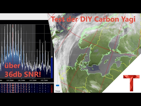
Building a DIY Carbon Fibre Yagi Antenna with 3D Printed Parts for 20€
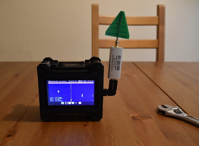
Over on his blog author Manuel a.k.a ‘Tysonpower’ has written about a DIY Carbon Fibre Yagi antenna that he’s built for only 20€. The antenna is very lightweight thanks to a 12mm diameter carbon fibre pipe which is used as the main boom. It also uses 3D printed parts that clamp onto the carbon fibre pipe and hold the metal elements in place. The advantage of the carbon fibre pipe over a PVC one is not only is it lightweight and much easier to hold, but it also stronger, and much less bendy and floppy. The metal elements are welding rods which he found on eBay, and the carbon fibre pipe was sourced cheaply from China with Aliexpress.
A Yagi is a directional antenna with high gain towards the direction it is pointing. You’ll need to hand point the Yagi in the general direction of the satellite as it passes over, but you can expect much higher SNR readings compared to something like a QFH or Turnstile.
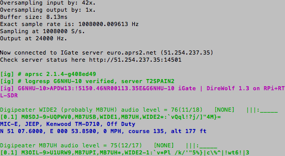
Manuel designed his antenna for 2M satellites (NOAA, Meteor M2, ISS etc), and was able to achieve over 36 dB SNR with an RTL-SDR.com V3 receiver, FM Trap and LNA4ALL on NOAA 18 at a 34° max. pass. He writes that the design is easily modifiable for other frequencies too.
To show off the design, construction and performance of his antenna he’s uploaded two videos to YouTube which we show below. The speech is in German, but even for non-German speakers the video is easily followed
![[EN subs] Yagi Antenne aus Carbon bauen (140mhz, 3 Elemente) - DIY](https://www.rtl-sdr.com/wp-content/plugins/wp-youtube-lyte/lyteCache.php?origThumbUrl=https%3A%2F%2Fi.ytimg.com%2Fvi%2FbNsvUdHIliI%2F0.jpg)