The R820T2 is the tuner chip used on most RTL-SDR dongles. It is also used on the Airspy, a more advanced higher end SDR. All in all, it is a very good tuner chip, but it is mostly limited by the low-bit ADC on the RTL2832U chip in the RTL-SDR.
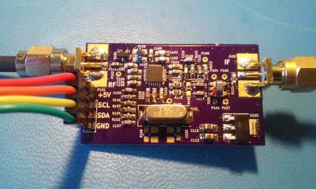
We’ve just been informed that there is now a custom DIY breakout board available for the R820T chip which is made by Eric Brombaugh who is an SDR experimenter. This is great for those wishing to do home brew SDR experiments with the R820T2 chip, for example you could perhaps implement your own SDR with a higher end ADC chip on a development boards.
The breakout board is essentially the exact implementation which is shown in the R820T datasheet. It is available as a 4-layer PCB on Osh Park and it “provides a simple 4-pin interface with power, ground and I2C bus for controlling the tuner. A broad-band RF input and 10MHz IF output are provided on SMA connectors.” Eric has also provided us with a simplified driver based on the Airspy and Linux media driver code which allows you to control the R820T2 from an STM32F0xx processor.
Recently RTL-SDR.com reader Mark wrote in and wanted to share his modified version of otti-soft’s GNU Radio flowgraph for decoding Meteor-M2 weather satellite images on Linux. The modified version allows for real time decoding, whereas the original version requires several offline decoding steps to be performed after recording the signal.
Mark writes:
I have modified one of otti-soft’s gnuradio flowgraphs so that they work with RTL-SDR and output the demodulated symbols to a TCP socket, from which the new version of LRPT Analizer (from robonuka.ru) can decode the data in real-time.
(AFAIK, only the AMIGOS version is able to decode the data from a socket, which is required for real-time decoding).
The program is to be run under a 32-bit version of Wine.
When the satellite is overhead, open and run the flowgraph (attached) in gnuradio-companion and leave it running. You might need to adjust the gain.
Then, run the LRPToffLineDecoder.exe executable from the extracted archive. It should display a constantly-updating constellation diagram. When the data is decoded, the channel images will start to appear in each section of the window.
That’s it, when the image is decoded, one can save it and close the windows of gnuradio-companion and the decoder.
Notes: when running the flowgraph, no other processes (rtl_sdr, rtl_power, gqrx, …) should use the SDR device.
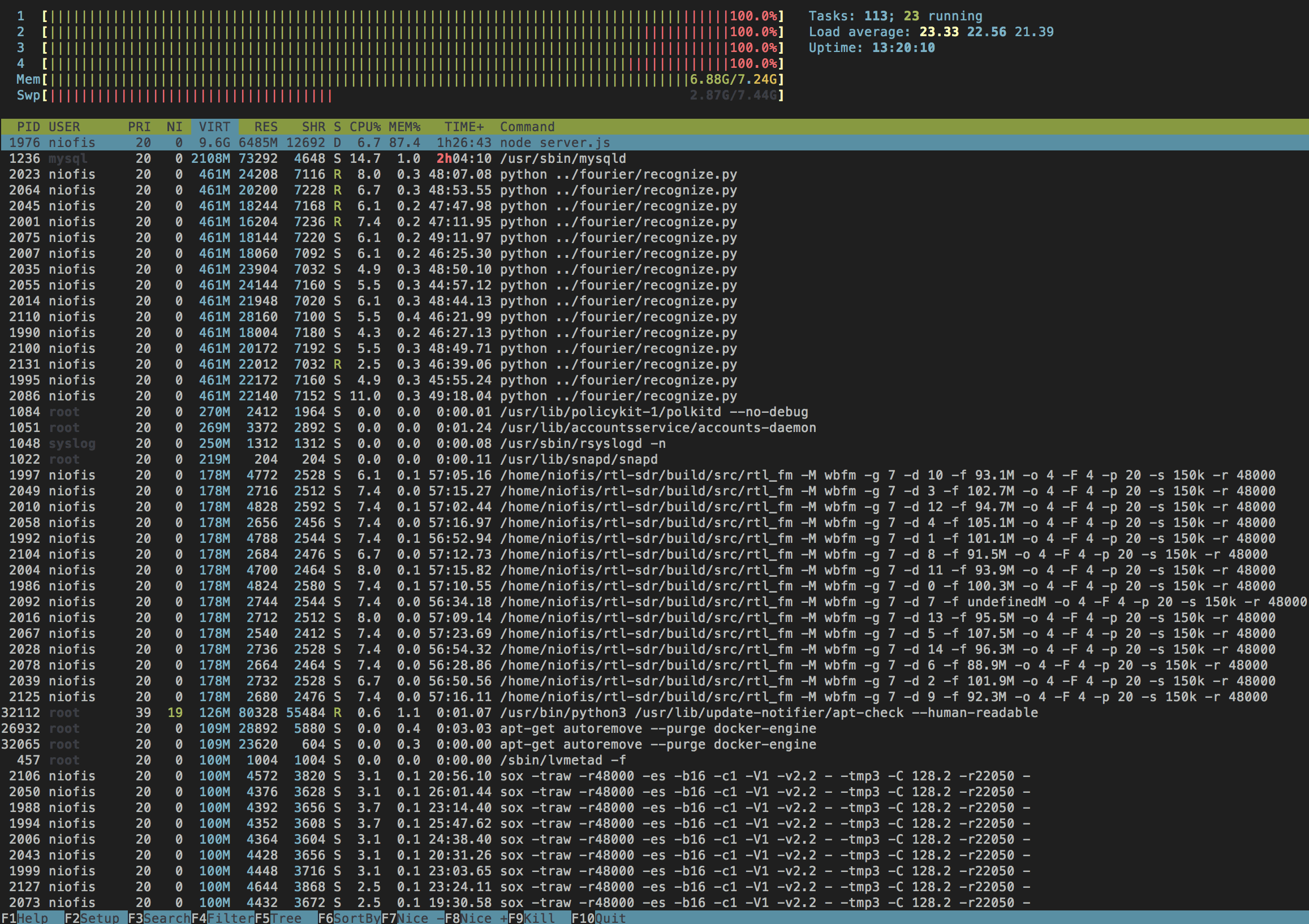
Enrique is working on a project which would record FM audio as MP3 files. To do this he uses rtl_fm with several RTL-SDR dongles. However, a major roadblock was that he found that adding five or more dongles to his server resulted in all dongles with a USB index over 3 producing the error “Failed to submit transfer 4!”.
After trying to work around the problem with Docker and VMs and ultimately failing he decided to look into other solutions. He found that rtl_test had an option to force synced output, and with this option enabled he was able to use more than four dongles. So he ended up implementing that synchronization code into rtl_fm.
With that code implemented he is now able to run up to 15 dongles on a single server. A higher amount might still be possible, but Enrique did not have that many dongles to test.
Update: On Keenerds branch he’s rejected a merge of this patch citing the following:
Synchronous mode doesn’t work. Rtl_fm used to use synchronous mode. It produced constant minor glitches that made data decoding impossible. Don’t use it.
The whole “many simultaneous dongles” problem is a well-known issue related to LibUSB. All you need to do is reduce the DEFAULT_BUF_NUMBER in librtlsdr.c and recompile.
UPDATE: Unfortunately we have been informed that the code base of this software was illegally decompiled and reused in an almost unchanged way from an already available closed source decoder. This means the program itself is illegal and totally unethical.
Please respect the original developers hard work and do not download this software.
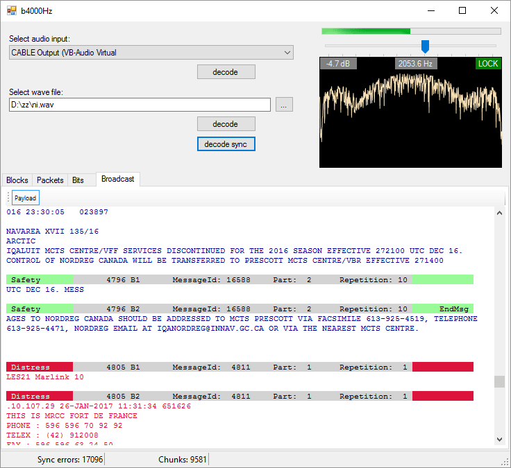
A new STD-C Inmarsat decoder called —-Hz has recently been released. The decoder is Windows based and simply listens to the demodulated Inmarsat STD-C audio from a program such as SDR#. This means that it is compatible with the RTL-SDR, and any other SDR that can receive Inmarsat.
We gave the software a brief test and it ran very well, and managed to decode several SafeteNET messages without issue, maintaining a good lock most of the time. The author writes that he plans to improve on the software in the future by creating a web service based version of the software.
Currently there are two other Inmarsat decoders available. One is called InmarsatDecoder and the other is the Tekmanoid decoder. The InmarsatDecoder is generally regarded as the best, but the Tekmanoid decoder was recently updated for improved performance. The new software appears to be about the same as the Tekmanoid decoder.
Inmarsat STD-C messages are broadcast from geostationary satellites in the L-band at around 1.5 Ghz. They send mostly marine based messages such as the following quoted from the ——Hz website:
Safety: high seas, tropical storm warnings, ice accretion…
Shipping activity: moving oil rigs, submarine cable deployment and repairs…
Distress reports: MOB, ships lost at sea, migrant ship reports…
Military exercises (firing practice, no fly zones…)
Pirate at sea reports…
If you are interested in learning how to decode STD-C we also have a tutorial available here.
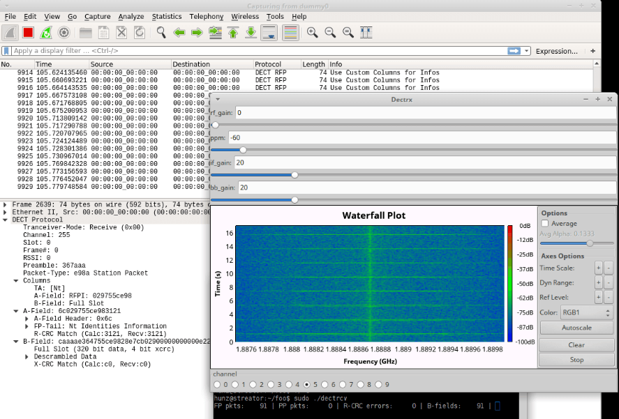
Over on GitHub programmer ‘znuh’ has uploaded a new RTL-SDR compatible GNURadio based tool for DECT decoding. DECT is an acronym for ‘Digital Enhanced Cordless Telecommunications’, and is the wireless standard used by modern digital cordless phones. In most countries DECT communications take place at 1880 – 1900 MHz, and in the USA at 1920 – 1930 MHz. So in order to receive these frequencies you’ll need an RTL-SDR with an E4000 chip, or some other compatible SDR that can tune this high.
It appears that the decoder is not actually able to decode audio (at least not yet or without extra work perhaps), but it can at least output the DECT packets to Wireshark for analysis. This may be of interest to those wanting to learn more about the DECT protocol.
Update: Over on the Reddit thread for this software the original poster ‘sanjuro’ has given a hint on how to (in theory) decode the audio, he writes:
A Bulgarian made antenna by LZ3RR – $31 USD + shipping
A Slovakian made collinear antenna by stanislavpalo130 – $25 USD + shipping
A Slovakian made 5/8 antenna by stanislavpalo130 – $24 USD
RTL-SDR stock antenna – Included with generic RTL-SDRs
A 3.5 dBi loaded whip – $3 to $15 USD
In summary the tests seem to show that nothing beats the FlightAware antenna, with the closest in performance being the Bulgarian made antenna. We should mention however, without knowing the real radiation patterns, SWR and various other factors it is hard to say which one will work best for everyone. Different locations/obstacles/mountings could mean that antennas with different designs and therefore radiation patterns work better than others. But it seems that the FlightAware antenna is the top performer in the common scenario of being able to mount the antenna on a roof with a good view of the horizon.
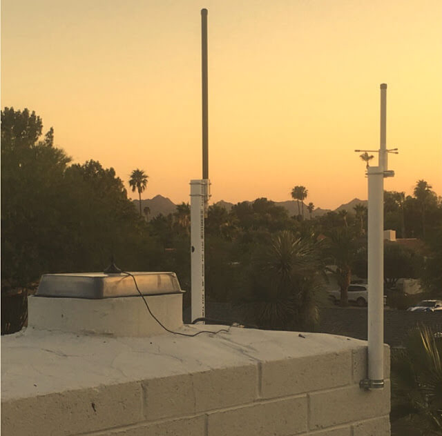
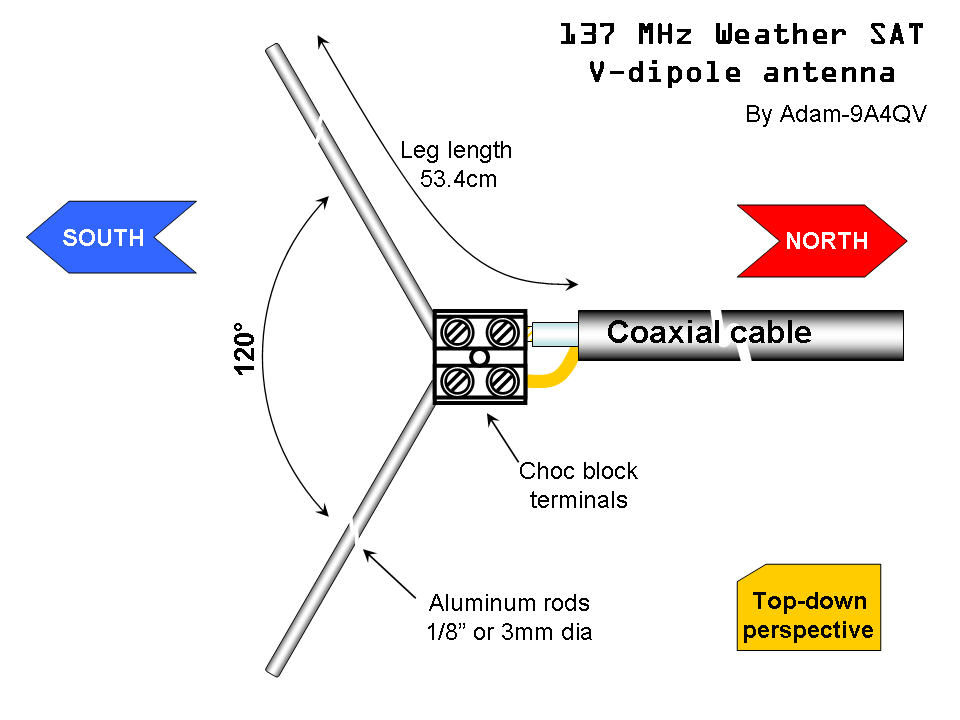
Over on his blog Adam 9A4QV (seller of various RTL-SDR related goods including the LNA4ALL) has just made a post detailing a build of a high performance super simple NOAA/Meteor M2 weather satellite antenna. Most antenna designs for polar orbiting weather spacecraft are based on circularly polarized turnstile or QFH designs. However, Adams antenna is based on a very simple linearly polarized dipole, which makes construction almost trivial.
The idea is that by arranging a dipole into a horizontal ‘V’ shape, the radiation pattern will be directed skywards in a figure 0 (zero) pattern. This will be optimal for satellites travelling in front, above and behind the antenna. Since polar orbiting satellites always travel North to South or vice versa, we can take advantage of this fact simply by orienting the antenna North/South.
There is also another advantage to Adams design. Since the antenna is horizontally polarized, all vertically polarized terrestrial signals will be reduced by 20 dB. Most terrestrial signals are broadcast in vertical polarization, so this can help significantly reduce interference and overloading on your RTL-SDR. Overloading is a big problem for many trying to receive weather satellites as they transmit at 137 MHz, which is close to the very powerful FM broadcast band, air band, pagers and business radio. In contrast a circularly polarized antenna like a QFH or turnstile only reduces vertically polarized terrestrial signals by 3 dB.
As the satellites broadcast in circular polarization there will be a 3 dB loss in Adams design from using a linear polarized antenna. But this can be considered as almost negligible. Adam also argues that the home construction of a QFH can never be perfect, so there will always be at least a ~1dB loss from inaccurate construction of these antennas anyway.
The final advantage to Adams design is that construction is extremely simple. Just connect one element to the center coax conductor, and the other to the shield, and spread apart by 120 degrees.
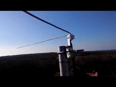
Adam 9A4QV’s V-Dipole for 137 MHz Weather Satellites.
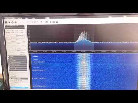
Adam has tested the antenna and has gotten excellent results. If you want more information about the antenna design, Adam has also uploaded a pdf with a more indepth description of the design and his thoughts.
DIY 137 MHz WX sat V-dipole antenna
137 MHz NOAA WX sat reception using V-dipole antenna
The RTL-SDR can be used to receive, decode and plot Global Positioning System (GPS) data in real time. To do this the RTL-SDR must be connected to a GPS antenna.
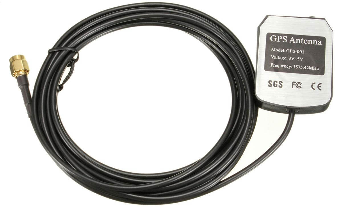
Extremely cheap $5 or less active GPS antennas with SMA connectors can be found on eBay, Amazon or Aliexpress. These GPS antennas contain a small ceramic patch antenna, a low noise amplifier and a GPS filter. In order to power the LNA in the antenna, you'll need to have an RTL-SDR with bias tee. Our RTL-SDR.com V3 dongles have this feature built in, but if you don't have a V3 you could also use a homebrew 5V external bias tee module or hack it into a standard RTL-SDR if you desired.
Also note that most standard R820T/2 RTL-SDRs fail to receive after a few minutes at frequencies above about 1.3 GHz due to heat issues. Our RTL-SDR.com V3 dongles don't have this problem in most climates thanks to the metal case cooling and improved thermal design on the PCB. If you experience this problem it can also be alleviated by using the special L-Band RTL-SDR drivers.
A typical $3 GPS antenna
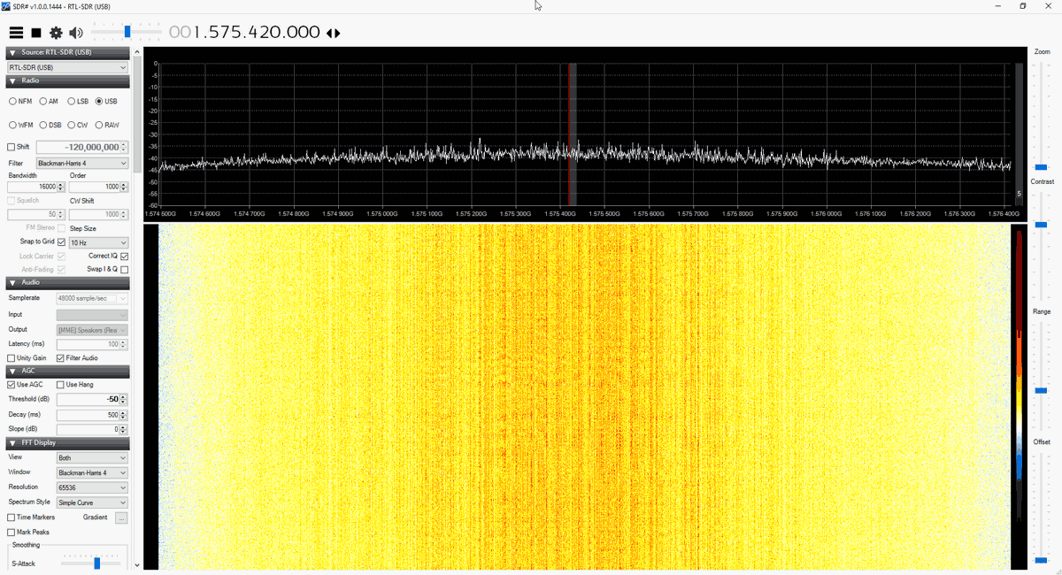
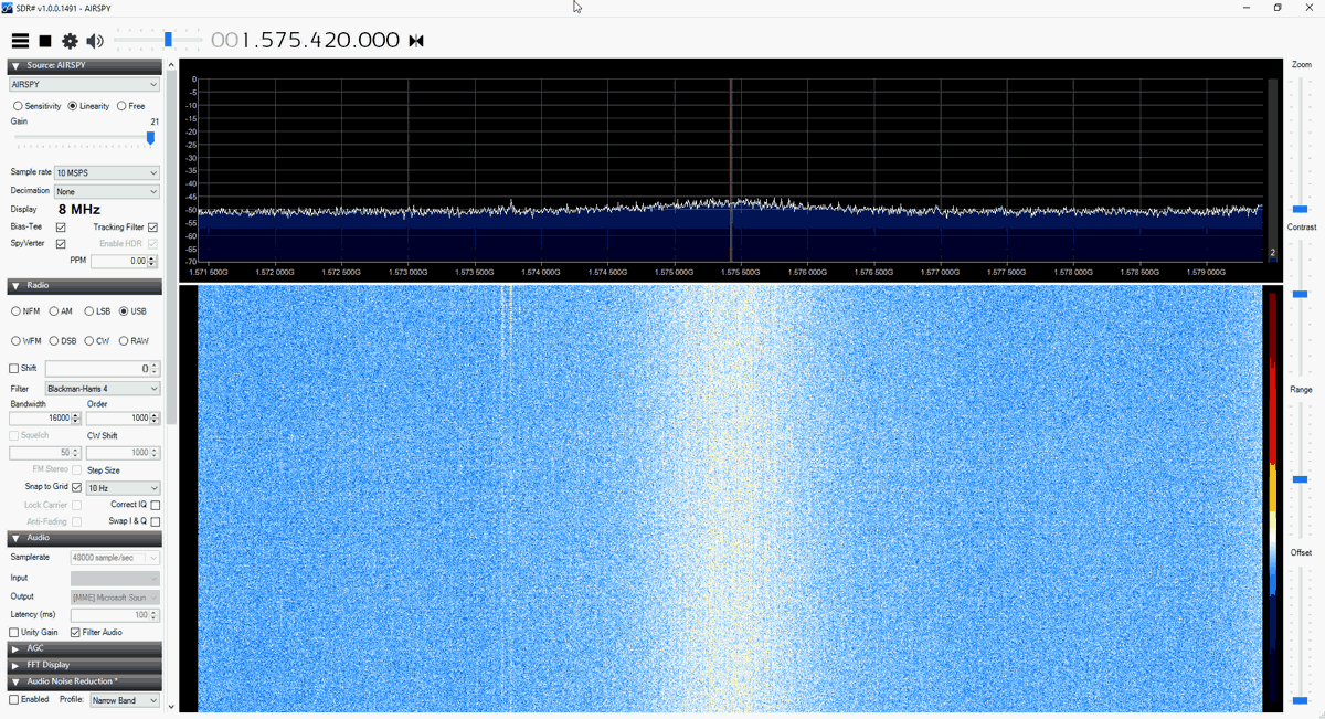
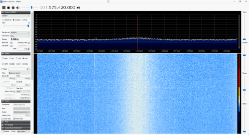
The main GPS frequency is 1.575420 GHz, but most of this signal is very weak and below the noise floor. If you were try to view the spectrum of GPS in SDR# you will find that you won't see much other than perhaps a very weak hump. Only through clever signal processing is such a weak signal actually recovered. Below we show screenshots of the GPS spectrum as seen by an RTL-SDR and more wideband Airspy R2 SDR.
The following tutorial shows how to receive and decode GPS signals and get a coordinate on a map of your location, using only an RTL-SDR dongle (with bias tee) and GPS antenna. This tutorial is based heavily on Philip Hahn's blog post at sdrgps.blogspot.com/2015/12/first-proof-of-concept-gps-fix-in.html.
Download GNSS-SDRLIB from github.com/taroz/GNSS-SDRLIB. On GitHub click on the green “Clone or download” button on the right and then click “Download ZIP”. Extract the zip file into a convenient folder on your PC. If you want to use the modified L-band drivers, copy the modified rtlsdr.dll into the the bin folder.
Make sure your RTL-SDR is plugged in, and that the bias tee has been activated (V3 software for activating the bias tee, see feature 2).
In the GNSS-SDRLIB folder, open gnss-sdrgui.exe. This will be stored in the bin subfolder.
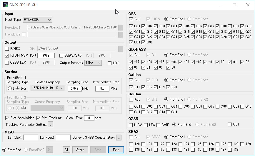
Now set the following parameters:
Change the Input Type to RTL-SDR
Place a check next to RTCM MSM , and set the Port to 9999.
Ensure that “Output Interval” is set to 10Hz.
Ensure that “Plot Acquisition” and “Plot Tracking” are both checked.
Under “MISC” optionally enter your approximate latitude and longitude to help with getting an initial lock..
Under the GPS, GLONASS and Galileo headings ensure that the “ALL”
Apply appropriate settings in GNSS-SDRLIB GUI
Press Start. A bunch of command windows will begin opening and closing for a few seconds. After that, a bunch of gnuplot graph windows will open up. These can be ignored.
Next go to the extracted RTK-NAVI folder, and enter the bin directory. Open the rtlnavi.exe file.
Click on the “I” button in the upper right region.
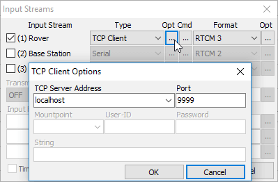
Place a check mark next to (1) Rover, and change the “Type” to TCP Client, and the “Format” to RTCM3. Click on the button with three dots under the leftmost “Opt” and set the “TCP Server Address” to localhost, and the “Port” to 9999. Press the OK button to exit the two windows.
Set the input stream
Now press Start in RTK-NAVI.
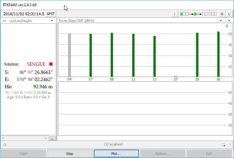
You should now see several bars in the top graph. These bars show GPS signal strengths for satellites. After a short time you should see a solution in the left panel which will be your current coordinates. If no solution ever comes, try respositioning your GPS antenna for a better view of the sky, and double checking that the bias tee is activated. Sometimes simply restarting GNSS-SDRLIB can fix no solution being found.
Check reception and wait for GPS lock solution.
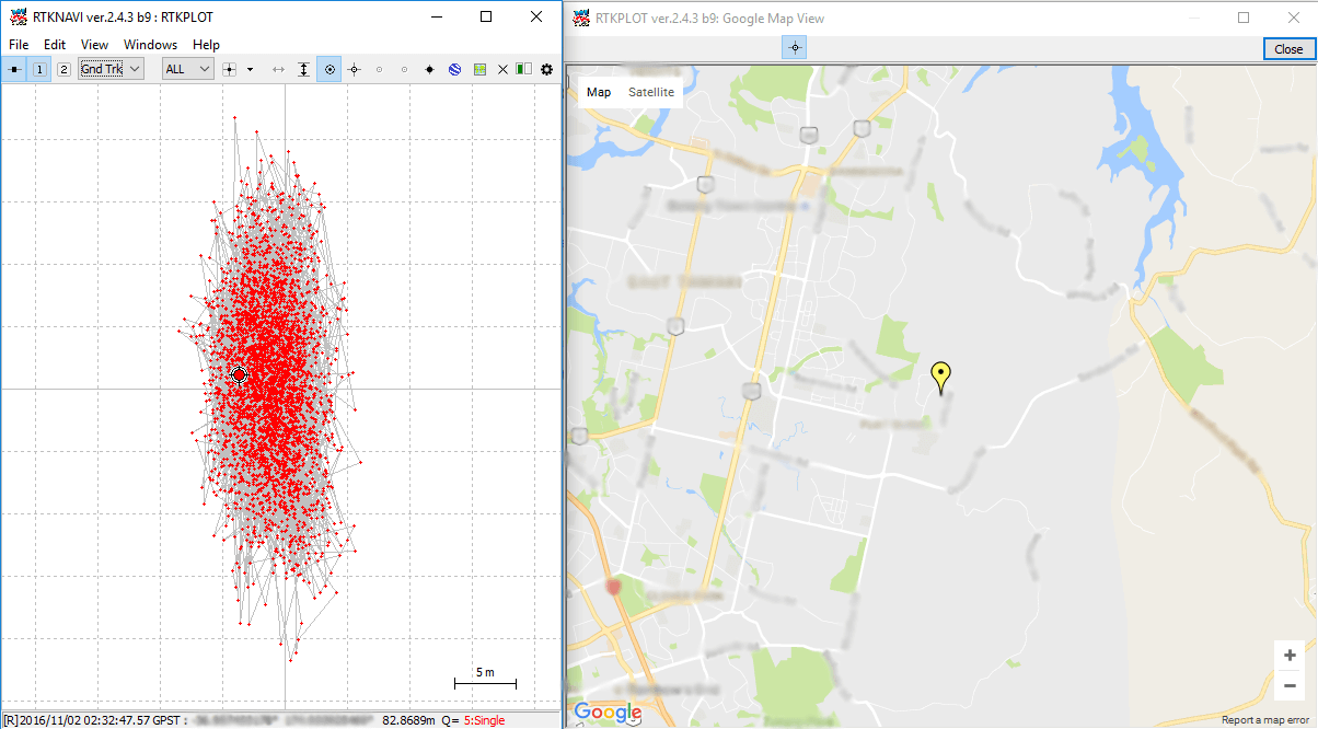
In RTK-NAVI click on the “Plot” button. This will open a positional plot of the recorded coordinates. To view your position on a Google map, click View → Google Map View. If everything is working correctly you should now be seeing an accurate marker of your current location.
The R820T2 is the tuner chip used on most RTL-SDR dongles. It is also used on the Airspy, a more advanced higher end SDR. All in all, it is a very good tuner chip, but it is mostly limited by the low-bit ADC on the RTL2832U chip in the RTL-SDR.
We’ve just been informed that there is now a custom DIY breakout board available for the R820T chip which is made by Eric Brombaugh who is an SDR experimenter. This is great for those wishing to do home brew SDR experiments with the R820T2 chip, for example you could perhaps implement your own SDR with a higher end ADC chip on a development boards.
The breakout board is essentially the exact implementation which is shown in the R820T datasheet. It is available as a 4-layer PCB on Osh Park and it “provides a simple 4-pin interface with power, ground and I2C bus for controlling the tuner. A broad-band RF input and 10MHz IF output are provided on SMA connectors.” Eric has also provided us with a simplified driver based on the Airspy and Linux media driver code which allows you to control the R820T2 from an STM32F0xx processor.
Recently RTL-SDR.com reader Mark wrote in and wanted to share his modified version of otti-soft’s GNU Radio flowgraph for decoding Meteor-M2 weather satellite images on Linux. The modified version allows for real time decoding, whereas the original version requires several offline decoding steps to be performed after recording the signal.
Mark writes:
I have modified one of otti-soft’s gnuradio flowgraphs so that they work with RTL-SDR and output the demodulated symbols to a TCP socket, from which the new version of LRPT Analizer (from robonuka.ru) can decode the data in real-time.
(AFAIK, only the AMIGOS version is able to decode the data from a socket, which is required for real-time decoding).
The program is to be run under a 32-bit version of Wine.
When the satellite is overhead, open and run the flowgraph (attached) in gnuradio-companion and leave it running. You might need to adjust the gain.
Then, run the LRPToffLineDecoder.exe executable from the extracted archive. It should display a constantly-updating constellation diagram. When the data is decoded, the channel images will start to appear in each section of the window.
That’s it, when the image is decoded, one can save it and close the windows of gnuradio-companion and the decoder.
Notes: when running the flowgraph, no other processes (rtl_sdr, rtl_power, gqrx, …) should use the SDR device.
Enrique is working on a project which would record FM audio as MP3 files. To do this he uses rtl_fm with several RTL-SDR dongles. However, a major roadblock was that he found that adding five or more dongles to his server resulted in all dongles with a USB index over 3 producing the error “Failed to submit transfer 4!”.
After trying to work around the problem with Docker and VMs and ultimately failing he decided to look into other solutions. He found that rtl_test had an option to force synced output, and with this option enabled he was able to use more than four dongles. So he ended up implementing that synchronization code into rtl_fm.
With that code implemented he is now able to run up to 15 dongles on a single server. A higher amount might still be possible, but Enrique did not have that many dongles to test.
Update: On Keenerds branch he’s rejected a merge of this patch citing the following:
Synchronous mode doesn’t work. Rtl_fm used to use synchronous mode. It produced constant minor glitches that made data decoding impossible. Don’t use it.
The whole “many simultaneous dongles” problem is a well-known issue related to LibUSB. All you need to do is reduce the DEFAULT_BUF_NUMBER in librtlsdr.c and recompile.
UPDATE: Unfortunately we have been informed that the code base of this software was illegally decompiled and reused in an almost unchanged way from an already available closed source decoder. This means the program itself is illegal and totally unethical.
Please respect the original developers hard work and do not download this software.
A new STD-C Inmarsat decoder called —-Hz has recently been released. The decoder is Windows based and simply listens to the demodulated Inmarsat STD-C audio from a program such as SDR#. This means that it is compatible with the RTL-SDR, and any other SDR that can receive Inmarsat.
We gave the software a brief test and it ran very well, and managed to decode several SafeteNET messages without issue, maintaining a good lock most of the time. The author writes that he plans to improve on the software in the future by creating a web service based version of the software.
Currently there are two other Inmarsat decoders available. One is called InmarsatDecoder and the other is the Tekmanoid decoder. The InmarsatDecoder is generally regarded as the best, but the Tekmanoid decoder was recently updated for improved performance. The new software appears to be about the same as the Tekmanoid decoder.
Inmarsat STD-C messages are broadcast from geostationary satellites in the L-band at around 1.5 Ghz. They send mostly marine based messages such as the following quoted from the ——Hz website:
Safety: high seas, tropical storm warnings, ice accretion…
Shipping activity: moving oil rigs, submarine cable deployment and repairs…
Distress reports: MOB, ships lost at sea, migrant ship reports…
Military exercises (firing practice, no fly zones…)
Pirate at sea reports…
If you are interested in learning how to decode STD-C we also have a tutorial available here.
Over on GitHub programmer ‘znuh’ has uploaded a new RTL-SDR compatible GNURadio based tool for DECT decoding. DECT is an acronym for ‘Digital Enhanced Cordless Telecommunications’, and is the wireless standard used by modern digital cordless phones. In most countries DECT communications take place at 1880 – 1900 MHz, and in the USA at 1920 – 1930 MHz. So in order to receive these frequencies you’ll need an RTL-SDR with an E4000 chip, or some other compatible SDR that can tune this high.
It appears that the decoder is not actually able to decode audio (at least not yet or without extra work perhaps), but it can at least output the DECT packets to Wireshark for analysis. This may be of interest to those wanting to learn more about the DECT protocol.
Update: Over on the Reddit thread for this software the original poster ‘sanjuro’ has given a hint on how to (in theory) decode the audio, he writes:
A Bulgarian made antenna by LZ3RR – $31 USD + shipping
A Slovakian made collinear antenna by stanislavpalo130 – $25 USD + shipping
A Slovakian made 5/8 antenna by stanislavpalo130 – $24 USD
RTL-SDR stock antenna – Included with generic RTL-SDRs
A 3.5 dBi loaded whip – $3 to $15 USD
In summary the tests seem to show that nothing beats the FlightAware antenna, with the closest in performance being the Bulgarian made antenna. We should mention however, without knowing the real radiation patterns, SWR and various other factors it is hard to say which one will work best for everyone. Different locations/obstacles/mountings could mean that antennas with different designs and therefore radiation patterns work better than others. But it seems that the FlightAware antenna is the top performer in the common scenario of being able to mount the antenna on a roof with a good view of the horizon.
Over on his blog Adam 9A4QV (seller of various RTL-SDR related goods including the LNA4ALL) has just made a post detailing a build of a high performance super simple NOAA/Meteor M2 weather satellite antenna. Most antenna designs for polar orbiting weather spacecraft are based on circularly polarized turnstile or QFH designs. However, Adams antenna is based on a very simple linearly polarized dipole, which makes construction almost trivial.
The idea is that by arranging a dipole into a horizontal ‘V’ shape, the radiation pattern will be directed skywards in a figure 0 (zero) pattern. This will be optimal for satellites travelling in front, above and behind the antenna. Since polar orbiting satellites always travel North to South or vice versa, we can take advantage of this fact simply by orienting the antenna North/South.
There is also another advantage to Adams design. Since the antenna is horizontally polarized, all vertically polarized terrestrial signals will be reduced by 20 dB. Most terrestrial signals are broadcast in vertical polarization, so this can help significantly reduce interference and overloading on your RTL-SDR. Overloading is a big problem for many trying to receive weather satellites as they transmit at 137 MHz, which is close to the very powerful FM broadcast band, air band, pagers and business radio. In contrast a circularly polarized antenna like a QFH or turnstile only reduces vertically polarized terrestrial signals by 3 dB.
As the satellites broadcast in circular polarization there will be a 3 dB loss in Adams design from using a linear polarized antenna. But this can be considered as almost negligible. Adam also argues that the home construction of a QFH can never be perfect, so there will always be at least a ~1dB loss from inaccurate construction of these antennas anyway.
The final advantage to Adams design is that construction is extremely simple. Just connect one element to the center coax conductor, and the other to the shield, and spread apart by 120 degrees.
Adam 9A4QV’s V-Dipole for 137 MHz Weather Satellites.
Adam has tested the antenna and has gotten excellent results. If you want more information about the antenna design, Adam has also uploaded a pdf with a more indepth description of the design and his thoughts.
DIY 137 MHz WX sat V-dipole antenna
137 MHz NOAA WX sat reception using V-dipole antenna
The RTL-SDR can be used to receive, decode and plot Global Positioning System (GPS) data in real time. To do this the RTL-SDR must be connected to a GPS antenna.
Extremely cheap $5 or less active GPS antennas with SMA connectors can be found on eBay, Amazon or Aliexpress. These GPS antennas contain a small ceramic patch antenna, a low noise amplifier and a GPS filter. In order to power the LNA in the antenna, you'll need to have an RTL-SDR with bias tee. Our RTL-SDR.com V3 dongles have this feature built in, but if you don't have a V3 you could also use a homebrew 5V external bias tee module or hack it into a standard RTL-SDR if you desired.
Also note that most standard R820T/2 RTL-SDRs fail to receive after a few minutes at frequencies above about 1.3 GHz due to heat issues. Our RTL-SDR.com V3 dongles don't have this problem in most climates thanks to the metal case cooling and improved thermal design on the PCB. If you experience this problem it can also be alleviated by using the special L-Band RTL-SDR drivers.
A typical $3 GPS antenna
The main GPS frequency is 1.575420 GHz, but most of this signal is very weak and below the noise floor. If you were try to view the spectrum of GPS in SDR# you will find that you won't see much other than perhaps a very weak hump. Only through clever signal processing is such a weak signal actually recovered. Below we show screenshots of the GPS spectrum as seen by an RTL-SDR and more wideband Airspy R2 SDR.
The following tutorial shows how to receive and decode GPS signals and get a coordinate on a map of your location, using only an RTL-SDR dongle (with bias tee) and GPS antenna. This tutorial is based heavily on Philip Hahn's blog post at sdrgps.blogspot.com/2015/12/first-proof-of-concept-gps-fix-in.html.
Download GNSS-SDRLIB from github.com/taroz/GNSS-SDRLIB. On GitHub click on the green “Clone or download” button on the right and then click “Download ZIP”. Extract the zip file into a convenient folder on your PC. If you want to use the modified L-band drivers, copy the modified rtlsdr.dll into the the bin folder.
Make sure your RTL-SDR is plugged in, and that the bias tee has been activated (V3 software for activating the bias tee, see feature 2).
In the GNSS-SDRLIB folder, open gnss-sdrgui.exe. This will be stored in the bin subfolder.
Now set the following parameters:
Change the Input Type to RTL-SDR
Place a check next to RTCM MSM , and set the Port to 9999.
Ensure that “Output Interval” is set to 10Hz.
Ensure that “Plot Acquisition” and “Plot Tracking” are both checked.
Under “MISC” optionally enter your approximate latitude and longitude to help with getting an initial lock..
Under the GPS, GLONASS and Galileo headings ensure that the “ALL”
Apply appropriate settings in GNSS-SDRLIB GUI
Press Start. A bunch of command windows will begin opening and closing for a few seconds. After that, a bunch of gnuplot graph windows will open up. These can be ignored.
Next go to the extracted RTK-NAVI folder, and enter the bin directory. Open the rtlnavi.exe file.
Click on the “I” button in the upper right region.
Place a check mark next to (1) Rover, and change the “Type” to TCP Client, and the “Format” to RTCM3. Click on the button with three dots under the leftmost “Opt” and set the “TCP Server Address” to localhost, and the “Port” to 9999. Press the OK button to exit the two windows.
Set the input stream
Now press Start in RTK-NAVI.
You should now see several bars in the top graph. These bars show GPS signal strengths for satellites. After a short time you should see a solution in the left panel which will be your current coordinates. If no solution ever comes, try respositioning your GPS antenna for a better view of the sky, and double checking that the bias tee is activated. Sometimes simply restarting GNSS-SDRLIB can fix no solution being found.
Check reception and wait for GPS lock solution.
In RTK-NAVI click on the “Plot” button. This will open a positional plot of the recorded coordinates. To view your position on a Google map, click View → Google Map View. If everything is working correctly you should now be seeing an accurate marker of your current location.