Tagged: rtl-sdr

Using an RTL-SDR to Listen to Superhet Radio’s Unintentional Emissions

Recently two students (Léo Poughon and his friend Thomas Daniel) wrote in to let us know about their work with SDR’s for their school project. Their project was to try and repeat the work of “Operation RAFTER” which was a technique use by MI5 in the 60’s to find hidden soviet spy radio equipment. Essentially, all superhet radios (almost any consumer radio is of the superhet design) will emit unintentional emissions from its local oscillator. By tuning to these unintentional emissions, and then emitting your own signal, it is then possible to know what frequency a radio is listening to.

They write the following:

As a french student (sorry for my bad english) in Higher School Preparatory Classes, I (and a friend) had to work with a rtl-sdr dongle for a school project. We tried to do, with the help of amateur radio near Toulouse (F6GUS, his club F5KUG) the same thing as the “RAFTER Operation” (https://en.wikipedia.org/wiki/Operation_RAFTER ) did during the 60′ : hearing at unintentional electromagnetic emissions coming from a widely-used consumer superhet receiver.

So because of its structure, a superheterodyne receiver (i.e. listening at FM broadcast) spreads some unintentional radiations due to the local oscillator upstream the mixer. Anybody with a suitable receiver (for example any rtl-sdr based dongle) can receive these emissions. Because of standards, in most FM radio the local oscillator (that is what the user actually tune) is tuned at the frequency he wants to listen plus 10.7 MHz. So if somebody in the close neighborhood is listening at a broadcast at 100 MHz, you will be able to “receive” its local oscillator at 110.7 MHz. (Please note it may be illegal in some countries to listen at these bands)

What is interesting is to know if a signal you receive at these frequency is actually coming from a radio receiver. During the RAFTER Operation, MI5 broadcast on the band they thought to be heard by soviet spies, and then listened for “the change in the superhet tone” to identify them.

We was able to receive with RTL-SDR the Local Oscillator of a superhet receiver we own.

rafter_1

We can see that the frequency isn’t stable on most of the time (the receiver was tuned to “France Info”, a french public station), but becomes stable sometime (when there is a “blank” between two news) : the frequency of the local oscillator “follows” what the superhet receiver demodulates.

Among other factors, a variation of the supply voltage of the local oscillator can make its frequency slightly shift. So we established experimentally a link between the supply voltage of our radio receiver and what is broadcast via the speaker (because when a speaker is using electrical current, the supply voltage slightly varies).

rafter_2

On the top, the HP voltage, and behind there is the supply voltage. Then, we saw that voltage variations could make the frequency to vary

capture du 2016-04-05

Here we supply the receiver (with a low frequency generator) making the supply voltage slightly varying and plot the frequency of local oscillator with a Python script we made.

Then, listening at the radio receiver local oscillator with GQRX and our RTL-SDR dongle, demodulating it with “narrow FM” demodulation and adapted parameters, we could hear with the PC (and obviously with poorer quality) what the radio receiver was listening at.

With the stock antenna we could hear at our radio only a dozen meters away, but with a homemade very low quality discone antenna we could receive it on another building, 60 meters away of our antenna. The ability to listen more or less the local oscillator broadcast depends also of the shielding of the radio receiver, its price (because a cheap radio will have a bad power supply and so its local oscillator frequency can “follow” what the speaker is telling, allowing us to “listen” at the local oscillator spike) and how you supply it (with the power grid or with batteries).

To conclude, we could (more or less depending on the previously cited parameters) know what a radio receiver in the neighbourhood was listening to using a RTL-SDR.

Modifying the Outernet LNA for Iridium Reception

A few days ago we posted a review on the Outernet LNA which can can be used to help receive their new L-band service signal. Their LNA uses a filter which restricts the frequency range from 1525 – 1559 MHz as this is the range in which the Outernet signals are located.

By default this LNA cannot be used to receive Iridium because the pass band on the default SAW filter does not cover the Irdidium frequency band of 1616 – 1626.5 MHz. Over on Reddit, devnulling decided to experiment with one of these LNA’s and see if he could replace the default SAW filter to enable Iridium reception. In his post he shows how he removes the default SAW filter, and replaces it with a Murata SF2250E SAW filter, which is the same size, but has a center frequency of 1615 MHz and a bandwidth of 20 MHz. Iridium is used for data services like satellite pagers, and with the right tools can be decoded.

We are also curious to see if this LNA could be modified to be used with GOES reception, which occurs at 1692 MHz.

Note: For those who had trouble with obtaining international shipping on these LNA’s the Outernet store now supports USPS international shipping, and NooElec appear to now be selling them on their site directly. Their products can also still be obtained on Amazon for US customers.

Additional Note Regarding the Downconverter: Also, it appears that the Outernet downconverter prototype that we posted about back in May has unfortunately been discontinued indefinitely and will not enter mass production. For now the LNA is the best option for receiving their signal.

Outernet LNA Modified for Iridium Reception

More videos showing HF reception on the RTL-SDR V3 Dongle

In this video icholakov from our last post continues his testing, and does some more tests on daytime HF reception.

RTL SDR V3 Dongle vs. SDR Play HF and MW part 2

In his third video he tests night time reception against the SDRplay.

RTL SDR Dongle V3 nighttime vs SDRPlay Part 3

In this video YouTube user Michael Jackson tests his RTL-SDR V3 at 8 MHz, with a dipole antenna.

RTL-SDR v3 Dongle on HF

Finally, in this video YouTube user jonny290 tests the V3 dongle on HF reception using CubicSDR.

A Preliminary Review of the HF Mode on Our V3 Dongles

Over on YouTube user icholakov shows a video where he compares our new RTL-SDR V3 dongles with direct sampling against an SDRplay and Icom 7100. The video shows reception at various HF frequencies on AM shortwave, time signals and SSB signals during day time reception. The performance seems to be fairly decent, but of course not as good as the more expensive SDRplay or Icom receivers.

This was originally posted on swling.com.

RTL Dongle V3 vs SDRPlay vs Icom 7100 Part 1

A New LabVIEW interface for RTL-SDR Dongles

Today LabVIEW and RTL-SDR user Albert Lederer wrote in to let us know that he’s created a new LabVIEW interface for the RTL-SDR. LabVIEW is a visual programming language which is used commonly by engineers and scientists to quickly build applications for things like product testing, system monitoring, instrument control etc.

Currently there is already a LabVIEW interface for the RTL-SDR available called sdrLab. However sdrLab uses rtl_tcp for communication which can cause poor responsiveness and issues with corporate firewalls. Albert’s solution is instead a wrapper for rtlsdr.dll which allows LabVIEW to gain direct access to the RTL-SDR.

On his post Albert has created a write up that explains how his driver works, and how it can be used with LabVIEW. Keep an eye on Alberts future posts, as he writes that he intends to post a part two, where he will show how to attach an RTL-SDR to an NI myRIO.

An FFT in LabVIEW
An FFT in LabVIEW

Review: Outernet LNA and Patch Antenna

Recently we posted news that Outernet had released their 1.5 GHz LNA, Patch Antenna and E4000 Elonics RTL-SDR + E4000/LNA Bundle. When used together, the products can be used to receive the Outernet L-band satellite signal, as well as other decodable L-band satellite signals like AERO and Inmarsat STD-C EGC. Outernet is a new satellite service that aims to be a free “library in the sky”. They continuously broadcast services such as news, weather, videos and other files from satellites.

EDIT: For international buyers the Outernet store has now started selling these products at http://store.outernet.is.

A few days ago we received the LNA and patch antenna for review. The patch antenna is similar to the one we received a while ago when writing our STD-C EGC tutorial, although this one is now slightly larger. It is roughly 12 x 12 cm in size, 100g heavy and comes with about 13 cm of high quality RG316 coax cable with a right angled SMA male connector on the end. The coax cable is clamped on the back for effective strain relief.

The Outernet patch antenna and LNA

The LNA is manufactured by NooElec for Outernet. It amplifies with 34 dB gain from 1525 – 1559 MHz, with its center frequency at 1542 MHz. It must be powered via a 3 – 5.5V bias tee and draws 25 mA. The package consists of a 5 x 2.5 cm PCB board with one female and one male SMA connector. The components are protected by a shielding can. Inside the shielding can we see a MAX12000 LNA chip along with a TA1405A SAW filter. The MAX12000 (datasheet here) is an LNA designed for GPS applications and has a NF of 1 dB. It has a design where there are two amplifiers embedded within the chip, and it allows you to connect a SAW filter in between them. The TA1405A SAW filter appears to be produced by Golledge (datasheet here), and it has about a 3 dB insertion loss.

The Outernet L-Band LNA
Inside the Outernet LNA

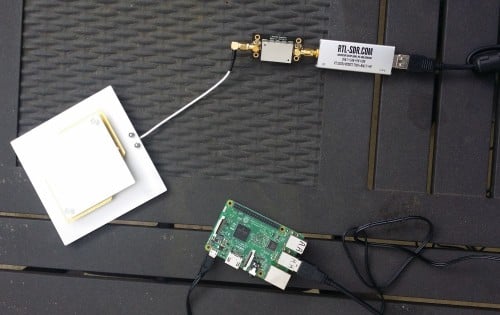
We tested the patch and LNA together with one of our V3 RTL-SDR Blog dongles, with the bias tee turned on. The LNA was connected directly to the dongle, with no coax in between. The patch antenna was angled to point towards the Inmarsat satellite. A 5 meter USB extension cord was then used to interface with a PC. The images below demonstrate the performance we were able to get.

Outernet Signal
Outernet Signal with 4x Decimation
AERO
STD-C EGC
Outernet Signal Outernet Signal with 4x Decimation AERO STD-C EGC

The Outernet team writes that a SNR level of only 2 dB is needed for decoding to work on their signal. With the patch and LNA we were able to get at least 12 dB so this is more than good enough. Other signals such as AERO and STD-C EGC also came in very strongly. Even when not angled at the satellite and placed flat on a table it was able to receive the signal with about 5 dB’s of SNR.

In conclusion the patch and LNA worked very well at receiving the Outernet signal as well as AERO and STD-C EGC. We think these products are great value for money if you are interested in these L-Band signals, and they make it very easy to receive. The only minor problem with the patch antenna is that there is no stand for it, which makes it difficult to mount in a way that faces the satellite. However this issue can easily be fixed with some sellotape and your own mount.

In the future once the Outernet Rpi3 OS and decoder image is released we hope to show a demonstration and tutorial on receiving Outernet data.

Using an RTL-SDR to Listen to Superhet Radio’s Unintentional Emissions

Recently two students (Léo Poughon and his friend Thomas Daniel) wrote in to let us know about their work with SDR’s for their school project. Their project was to try and repeat the work of “Operation RAFTER” which was a technique use by MI5 in the 60’s to find hidden soviet spy radio equipment. Essentially, all superhet radios (almost any consumer radio is of the superhet design) will emit unintentional emissions from its local oscillator. By tuning to these unintentional emissions, and then emitting your own signal, it is then possible to know what frequency a radio is listening to.

They write the following:

As a french student (sorry for my bad english) in Higher School Preparatory Classes, I (and a friend) had to work with a rtl-sdr dongle for a school project. We tried to do, with the help of amateur radio near Toulouse (F6GUS, his club F5KUG) the same thing as the “RAFTER Operation” (https://en.wikipedia.org/wiki/Operation_RAFTER ) did during the 60′ : hearing at unintentional electromagnetic emissions coming from a widely-used consumer superhet receiver.

So because of its structure, a superheterodyne receiver (i.e. listening at FM broadcast) spreads some unintentional radiations due to the local oscillator upstream the mixer. Anybody with a suitable receiver (for example any rtl-sdr based dongle) can receive these emissions. Because of standards, in most FM radio the local oscillator (that is what the user actually tune) is tuned at the frequency he wants to listen plus 10.7 MHz. So if somebody in the close neighborhood is listening at a broadcast at 100 MHz, you will be able to “receive” its local oscillator at 110.7 MHz. (Please note it may be illegal in some countries to listen at these bands)

What is interesting is to know if a signal you receive at these frequency is actually coming from a radio receiver. During the RAFTER Operation, MI5 broadcast on the band they thought to be heard by soviet spies, and then listened for “the change in the superhet tone” to identify them.

We was able to receive with RTL-SDR the Local Oscillator of a superhet receiver we own.

rafter_1

We can see that the frequency isn’t stable on most of the time (the receiver was tuned to “France Info”, a french public station), but becomes stable sometime (when there is a “blank” between two news) : the frequency of the local oscillator “follows” what the superhet receiver demodulates.

Among other factors, a variation of the supply voltage of the local oscillator can make its frequency slightly shift. So we established experimentally a link between the supply voltage of our radio receiver and what is broadcast via the speaker (because when a speaker is using electrical current, the supply voltage slightly varies).

rafter_2

On the top, the HP voltage, and behind there is the supply voltage. Then, we saw that voltage variations could make the frequency to vary

capture du 2016-04-05

Here we supply the receiver (with a low frequency generator) making the supply voltage slightly varying and plot the frequency of local oscillator with a Python script we made.

Then, listening at the radio receiver local oscillator with GQRX and our RTL-SDR dongle, demodulating it with “narrow FM” demodulation and adapted parameters, we could hear with the PC (and obviously with poorer quality) what the radio receiver was listening at.

With the stock antenna we could hear at our radio only a dozen meters away, but with a homemade very low quality discone antenna we could receive it on another building, 60 meters away of our antenna. The ability to listen more or less the local oscillator broadcast depends also of the shielding of the radio receiver, its price (because a cheap radio will have a bad power supply and so its local oscillator frequency can “follow” what the speaker is telling, allowing us to “listen” at the local oscillator spike) and how you supply it (with the power grid or with batteries).

To conclude, we could (more or less depending on the previously cited parameters) know what a radio receiver in the neighbourhood was listening to using a RTL-SDR.

Modifying the Outernet LNA for Iridium Reception

A few days ago we posted a review on the Outernet LNA which can can be used to help receive their new L-band service signal. Their LNA uses a filter which restricts the frequency range from 1525 – 1559 MHz as this is the range in which the Outernet signals are located.

By default this LNA cannot be used to receive Iridium because the pass band on the default SAW filter does not cover the Irdidium frequency band of 1616 – 1626.5 MHz. Over on Reddit, devnulling decided to experiment with one of these LNA’s and see if he could replace the default SAW filter to enable Iridium reception. In his post he shows how he removes the default SAW filter, and replaces it with a Murata SF2250E SAW filter, which is the same size, but has a center frequency of 1615 MHz and a bandwidth of 20 MHz. Iridium is used for data services like satellite pagers, and with the right tools can be decoded.

We are also curious to see if this LNA could be modified to be used with GOES reception, which occurs at 1692 MHz.

Note: For those who had trouble with obtaining international shipping on these LNA’s the Outernet store now supports USPS international shipping, and NooElec appear to now be selling them on their site directly. Their products can also still be obtained on Amazon for US customers.

Additional Note Regarding the Downconverter: Also, it appears that the Outernet downconverter prototype that we posted about back in May has unfortunately been discontinued indefinitely and will not enter mass production. For now the LNA is the best option for receiving their signal.

Outernet LNA Modified for Iridium Reception

More videos showing HF reception on the RTL-SDR V3 Dongle

In this video icholakov from our last post continues his testing, and does some more tests on daytime HF reception.

RTL SDR V3 Dongle vs. SDR Play HF and MW part 2

In his third video he tests night time reception against the SDRplay.

RTL SDR Dongle V3 nighttime vs SDRPlay Part 3

In this video YouTube user Michael Jackson tests his RTL-SDR V3 at 8 MHz, with a dipole antenna.

RTL-SDR v3 Dongle on HF

Finally, in this video YouTube user jonny290 tests the V3 dongle on HF reception using CubicSDR.

A Preliminary Review of the HF Mode on Our V3 Dongles

Over on YouTube user icholakov shows a video where he compares our new RTL-SDR V3 dongles with direct sampling against an SDRplay and Icom 7100. The video shows reception at various HF frequencies on AM shortwave, time signals and SSB signals during day time reception. The performance seems to be fairly decent, but of course not as good as the more expensive SDRplay or Icom receivers.

This was originally posted on swling.com.

RTL Dongle V3 vs SDRPlay vs Icom 7100 Part 1

A New LabVIEW interface for RTL-SDR Dongles

Today LabVIEW and RTL-SDR user Albert Lederer wrote in to let us know that he’s created a new LabVIEW interface for the RTL-SDR. LabVIEW is a visual programming language which is used commonly by engineers and scientists to quickly build applications for things like product testing, system monitoring, instrument control etc.

Currently there is already a LabVIEW interface for the RTL-SDR available called sdrLab. However sdrLab uses rtl_tcp for communication which can cause poor responsiveness and issues with corporate firewalls. Albert’s solution is instead a wrapper for rtlsdr.dll which allows LabVIEW to gain direct access to the RTL-SDR.

On his post Albert has created a write up that explains how his driver works, and how it can be used with LabVIEW. Keep an eye on Alberts future posts, as he writes that he intends to post a part two, where he will show how to attach an RTL-SDR to an NI myRIO.

An FFT in LabVIEW
An FFT in LabVIEW

Review: Outernet LNA and Patch Antenna

Recently we posted news that Outernet had released their 1.5 GHz LNA, Patch Antenna and E4000 Elonics RTL-SDR + E4000/LNA Bundle. When used together, the products can be used to receive the Outernet L-band satellite signal, as well as other decodable L-band satellite signals like AERO and Inmarsat STD-C EGC. Outernet is a new satellite service that aims to be a free “library in the sky”. They continuously broadcast services such as news, weather, videos and other files from satellites.

EDIT: For international buyers the Outernet store has now started selling these products at http://store.outernet.is.

A few days ago we received the LNA and patch antenna for review. The patch antenna is similar to the one we received a while ago when writing our STD-C EGC tutorial, although this one is now slightly larger. It is roughly 12 x 12 cm in size, 100g heavy and comes with about 13 cm of high quality RG316 coax cable with a right angled SMA male connector on the end. The coax cable is clamped on the back for effective strain relief.

The Outernet patch antenna and LNA

The LNA is manufactured by NooElec for Outernet. It amplifies with 34 dB gain from 1525 – 1559 MHz, with its center frequency at 1542 MHz. It must be powered via a 3 – 5.5V bias tee and draws 25 mA. The package consists of a 5 x 2.5 cm PCB board with one female and one male SMA connector. The components are protected by a shielding can. Inside the shielding can we see a MAX12000 LNA chip along with a TA1405A SAW filter. The MAX12000 (datasheet here) is an LNA designed for GPS applications and has a NF of 1 dB. It has a design where there are two amplifiers embedded within the chip, and it allows you to connect a SAW filter in between them. The TA1405A SAW filter appears to be produced by Golledge (datasheet here), and it has about a 3 dB insertion loss.

The Outernet L-Band LNA
Inside the Outernet LNA

We tested the patch and LNA together with one of our V3 RTL-SDR Blog dongles, with the bias tee turned on. The LNA was connected directly to the dongle, with no coax in between. The patch antenna was angled to point towards the Inmarsat satellite. A 5 meter USB extension cord was then used to interface with a PC. The images below demonstrate the performance we were able to get.

Outernet Signal
Outernet Signal with 4x Decimation
AERO
STD-C EGC
Outernet Signal Outernet Signal with 4x Decimation AERO STD-C EGC

The Outernet team writes that a SNR level of only 2 dB is needed for decoding to work on their signal. With the patch and LNA we were able to get at least 12 dB so this is more than good enough. Other signals such as AERO and STD-C EGC also came in very strongly. Even when not angled at the satellite and placed flat on a table it was able to receive the signal with about 5 dB’s of SNR.

In conclusion the patch and LNA worked very well at receiving the Outernet signal as well as AERO and STD-C EGC. We think these products are great value for money if you are interested in these L-Band signals, and they make it very easy to receive. The only minor problem with the patch antenna is that there is no stand for it, which makes it difficult to mount in a way that faces the satellite. However this issue can easily be fixed with some sellotape and your own mount.

In the future once the Outernet Rpi3 OS and decoder image is released we hope to show a demonstration and tutorial on receiving Outernet data.

Using a Beam Deflection Tube as a Mixer for an RTL-SDR Upconverter

Over on YouTube user Full spectrum technician has uploaded an interested video where he shows how he used a beam deflection tube to create an upconverter for his RTL-SDR. A beam deflection tube is a type of vacuum tube that can be used as a mixer. If you aren’t aware, a vacuum tube (a.k.a tube or valve) is an electrical component that was used in electrical equipment heavily back in the first half of the 1900’s. They could be used to implement circuits like amplifiers, mixers, switches, oscillators and more. Even today they are still used in some high end audio equipment because many people believe they produce superior audio quality. Full spectrum technician writes on his video:

A simple test using a 6ME8 beam deflection tube as a balanced mixer up converter for an RTL-SDR to enable HF reception.

The only problem I had was too much conversion gain. Even with a relatively short antenna, and literally starving the tube for voltage, the signal output levels were high enough that I had to crank back the gain of the RTL SDR and/or use padding on the input of the RTL-SDR.

The LO was feed to grid 1 for common mode input.
The antenna was feed to the two deflection plates via a transformer as a differential input.
The output was taken from the two anode plates via a transformer as a differential output.

That resulted in the LO balancing it’s self out on the output so that the LO would not overload the front end of the receiver.

Operating voltages at the time were..
20V anode.
5V deflection plates.
20V accelerator grid.
Cathode tied to ground.

Using a beam deflection vacuum tube as a mixer for an RTL-SDR up converter.

RTLSDR4Everyone: Review of the Soft66RTL3

Over on his blog Akos has posted a review of the Soft66RTL3. The Soft66RTL3 is an RTL-SDR which is retrofitted with an upconverter, filters and HF RF amp. It is produced by Kazunori Miura (JA7TDO) who is based in Japan and it sells for $40 USD shipped, or $46 USD shipped with registered air mail. Previously we posted Mike Ladds review of the Soft66RTL3 here.

In his review Akos shows us the features of the Soft66RTL3 which include the switch for selecting between several HF filters, as well as a trimmer pot for adjusting the amount of gain on the HF RF filter. He shows that inside is a nano sized RTL-SDR dongle soldered on to an upconverter board.

Unfortunately it seems Akos discovered some flaws with the unit. He discovered odd frequency drift behavior and poor performance on VHF and UHF. HF performance on the other hand was decent, but still not as good as with an upconverter.

Inside the Soft66RTL3