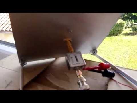
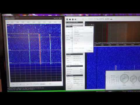
Over on YouTube user Veryokay has uploaded a video showing how he was able to receive WSPR (Weak Signal Propagation Report) signals at 14 MHz with his direct sampling modified RTL-SDR. WSPR is a HF mode designed to be received even if the signal is very weak. It is used to help determine radio propagation conditions. Direct sampling mode allows you to receive HF signals on an RTL-SDR without the need for an upconverter, but it is more difficult to implement and get good results with. To get the best results Veryokay built an add on PCB that fits onto the RTL-SDR which contains and LNA and single ended to differential operational amplifier to amplify and get correct impedance matching on the input.
His video mainly shows how to calibrate the receiver correctly to receive WSPR as incorrect calibration is the most common error when trying to receive WSPR for the first time. In the video he also explains that he is transmitting WSPR himself using his Raspberry Pi and a QRPi WSPR filter shield for use with Rpitx.
Receiving WSPR with the RTL-SDR in direct sampling mode and WSPR-X.
Receiving WSPR mode at 20m with RTL-SDR dongle in direct sampling
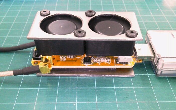
By cooling the dongle, and especially the R820T chip, Nobu writes that he sees improved ADS-B decoding performance as his range is increased. Without cooling the R820T chip can get quite hot and causes failing reception at around 1.5 GHz. Passive cooling is usually enough to fix reception at those higher frequencies, but active cooling via a fan can take it further and actually improve sensitivity slightly.
To add to his post, we suspect that the sensitivity of the R820T/2 front end reduces by about 0.5 dB at most when it heats up (after a few seconds), so forced air cooling should be able to improve sensitivity by about this much.
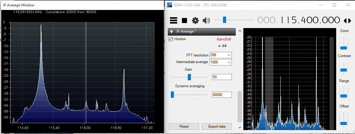
The IF Average tool is a RTL-SDR compatible plugin for SDR# which allows you to plot an average of the current spectrum shown in SDR#. This is especially useful for radio astronomers who often need to average the spectrum for a long time in order to get a good plot of the Hydrogen Line. Recently the plugin was updated to support newer versions of SDR# and to upgrade some features. Daniel Kaminski, the author of the plugin writes:
I used ultrafast FFT which works on 4k to 512k bit space. With this plugin it is possible to average up to 64000000 samples in real time. XNA allows to shows the calculation results in real time.
To install the plugin you will need to install the XNA Framework 4.0 Redistributable first. Then copy the plugin files over to the SDR# folder and add the “magicline” to the SDR# Plugins.xml file.
Back in April we posted about how KD0CQ found that he could receive signals up to 4.5 GHz with an RTL-SDR by using a $5 downconverter for DirecTV called the SUP-2400. The RTL-SDR can only receive up to a maximum frequency of about 1.7 GHz, but the SUP-2400 downconverter can be modified to convert frequencies at around 2.4 GHz down into a range receivable by the RTL-SDR.
When we first posted the story the instructions for modifying the SUP-2400 to use as a downconverter weren’t uploaded yet, but they are now. The modification requires decent soldering skills as it involves desoldering a few small SMD components and bridging some points with wires.
Over on YouTube user T3CHNOTURK has uploaded a video showing the downconverter in action. With the SUP-2400 downconverter and RTL-SDR he is able to receive some WiFi at 2.447 GHz as well as signals from a wireless keyboard at 2.465 GHz
RTLSDR Receiveing wifi & 2.4 ghz ism band with moded SUP-2400 Downconverter
One problem that sometimes arises when using embedded single board computers like the Raspberry Pi is that they often cannot provide enough current to power devices through the USB port.
Over on YouTube user KD9 BVO wanted to use his RTL-SDR with a Raspberry Pi, but found that the Raspberry Pi shut down whenever he plugged it in, due to it using too much current. To get around this problem he decided to build a DIY powered USB hub. This solution allows the RTL-SDR to be powered via the hub itself, rather than through the Raspberry Pi USB port.
In the video he takes an existing unpowered hub and shows how to modify it to provide power directly to the RTL-SDR via an external power supply.
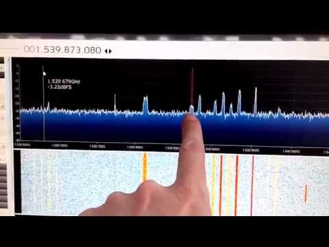
Adam 9A4QV has once again uploaded three new videos to YouTube, all related to L-band satellite reception. The first video shows how much L-band reception can be improved by using two LNA4ALL low noise amplifiers together with a filter placed in between them. Using two LNA’s instead of one improves the reception by about 2-6 dB. He also shows that L-band Inmarsat satellite signals at 1.5 GHz can even be received by his 1090 MHz folded monopole ADS-B antenna placed indoors.
The second video shows a reception report of the new Outernet signal. The Outernet signal is a new satellite data service being provided that broadcasts up to date news as well as various files and information such as educational videos and books for people in third world countries without internet. They have said that they are working on free decoding software for their service which should be released soon. The Outernet signal is a bit weaker than typical AERO signals, but can still be received quite easily with an RTL-SDR, patch antenna and 2 x LNA4ALL. The Outernet downconverter mentioned in a previous post should of course also work well.
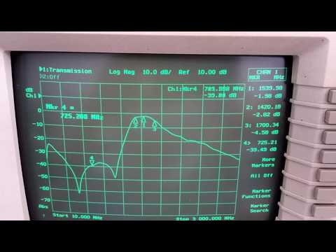
His third video shows some tests on his L-band filter, showing return and insertion loss.
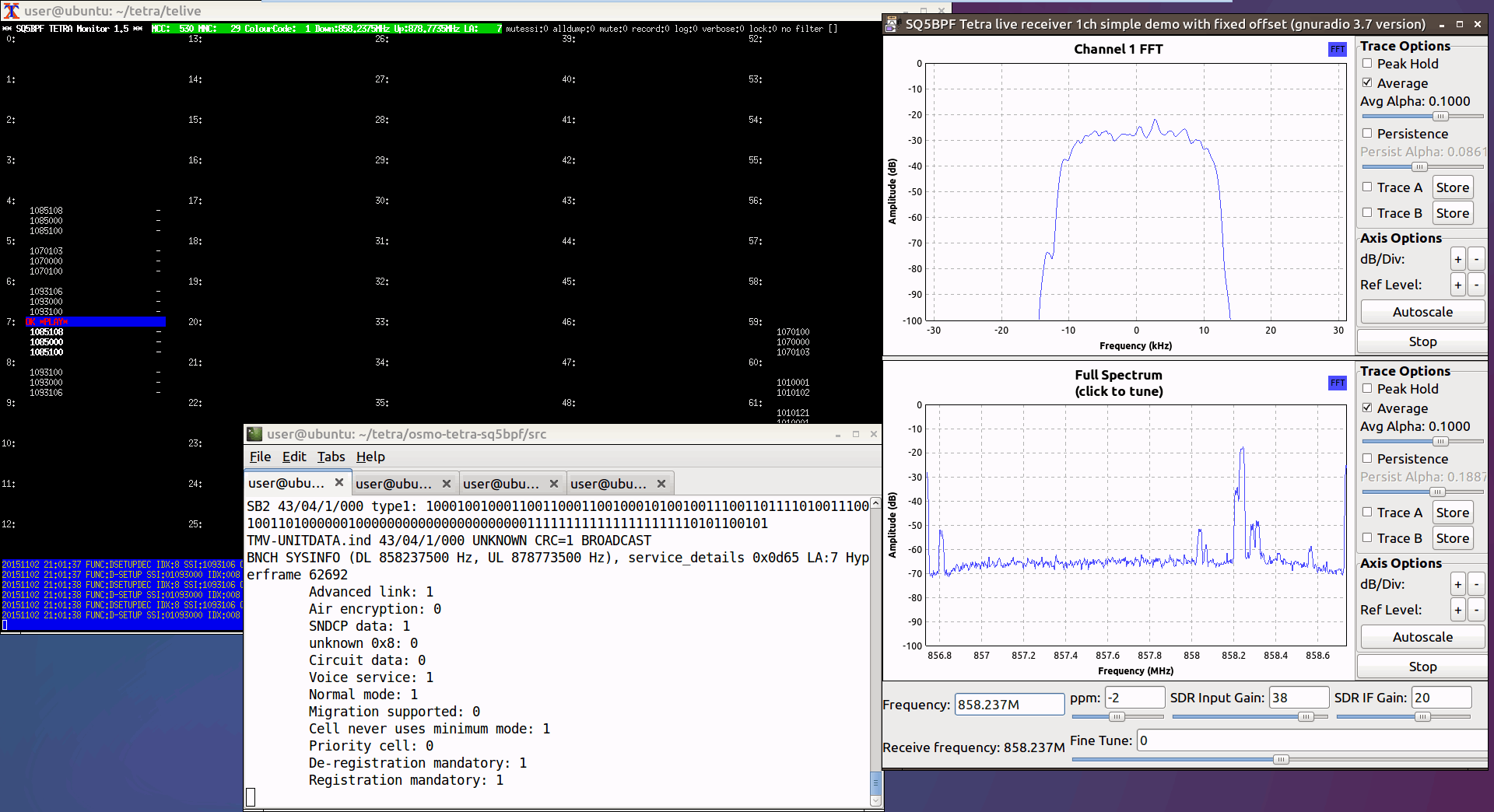
Dejan Ornig, a 26 year old student at the University of Maribor’s Faculty of Criminal Justice and Security was recently almost jailed for finding a security flaw in Police TETRA communications in his home country of Slovenia. Back in 2013 his University Computer Science class of 25 was assigned a task to research security vulnerabilities in TETRA. TETRA is a RF digital communications protocol often used by authorities due to its ability to be secured via encryption. During his research he used an RTL-SDR and the open source Osmocom TETRA decoder, and discovered a flaw in the Slovenian Police’s TETRA configuration which meant that encrypted communications were often being broadcast in the clear. Translated, Ornig said:
For $20 I bought a DVB-T receiver (RTL-SDR), on the Internet, I have found also freely available and open-source software OsmoCOM. Free access solution for decoding the signal Tetra eighth-tetra is already prepared in advance programming framework based on the platform GNU.
He goes on to say (translated):
I was even more surprised when I found that most users do not have authentication turned on the radio terminal, even though the Ministry of the Interior in the documents and tenders repeatedly wrote to all the radio terminals to access networks using authentication.
Shortly after discovering the flaw, Dejan privately contacted the authorities with his findings. But after two years of repeatedly contacting them and waiting for a fix, Dejan decided to take his story to a local news agency in February 2015. At this point the Slovenian Police became interested in Dejan, and instead of fixing the problem, decided to conduct a search on his house, seizing his computer and RTL-SDR. After the search the Police made life harder for Ornig by trying to lump on other problems. During the search they found a “counterfeit police badge” in his house and apparently accused him of impersonating a police officer, and after a search of his PC they also decided to charge him after finding out that he covertly recorded his ex-employer calling him an “idiot”.
Ornig has now been given a 15 month suspended jail sentence for attempting to “hack” the TETRA network. Fortunately the suspended part means that in order to not go to jail Ornig simply must not repeat his crime again within 3 years. While SDR’s and radios are not illegal in most countries this is a reminder to professional and amateur security researchers to check that what you are doing is legal in your country. Even if it is for the overall good, Police often do not have the technical competence to understand security researchers and may react illogically to findings. The good news about Ornig’s story is that apart from the suspended jail sentence the authorities appear to have now worked with him to fix the problems.
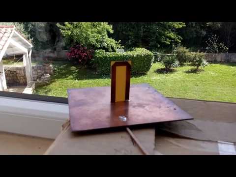
Over on YouTube Adam 9A4QV has uploaded a video showing how good L-band reception can be with only a cheap home made patch antenna, RTL-SDR dongle and LNA4ALL. The video is in response to a question on our previous post, which discussed the prototype Outernet downconverter. The question asked what difference can we expect with the downconverter compared to just using an LNA, like the LNA4ALL.
In the video Adam shows that L-Band reception with the LNA4ALL can be as good as with the downconverter. The main problem with L-band reception on the RTL-SDR is that some units tend to fail to receive properly at around 1.5 GHz. The downconverter bypasses this problem by receiving L-band at around 200 MHz instead. Though we believe that this problem is solved on the units we sell as we heatsink to a metal enclosure, and if that is not enough, it can be solved further by using this modified driver. The other advantages of the downconverter is that it includes filtering, an LNA, and allows you to use much longer runs of lossy cable, which is useful if for instance you want to put a permanent L-band antenna on the roof.


![[Bits #4] How to DIY a Powered USB Hub](https://www.rtl-sdr.com/wp-content/plugins/wp-youtube-lyte/lyteCache.php?origThumbUrl=https%3A%2F%2Fi.ytimg.com%2Fvi%2Fz-5ly2beNkg%2F0.jpg)