Tagged: rtl2832u

Modifying the Outernet LNA for Iridium Reception

A few days ago we posted a review on the Outernet LNA which can can be used to help receive their new L-band service signal. Their LNA uses a filter which restricts the frequency range from 1525 – 1559 MHz as this is the range in which the Outernet signals are located.

By default this LNA cannot be used to receive Iridium because the pass band on the default SAW filter does not cover the Irdidium frequency band of 1616 – 1626.5 MHz. Over on Reddit, devnulling decided to experiment with one of these LNA’s and see if he could replace the default SAW filter to enable Iridium reception. In his post he shows how he removes the default SAW filter, and replaces it with a Murata SF2250E SAW filter, which is the same size, but has a center frequency of 1615 MHz and a bandwidth of 20 MHz. Iridium is used for data services like satellite pagers, and with the right tools can be decoded.

We are also curious to see if this LNA could be modified to be used with GOES reception, which occurs at 1692 MHz.

Note: For those who had trouble with obtaining international shipping on these LNA’s the Outernet store now supports USPS international shipping, and NooElec appear to now be selling them on their site directly. Their products can also still be obtained on Amazon for US customers.

Additional Note Regarding the Downconverter: Also, it appears that the Outernet downconverter prototype that we posted about back in May has unfortunately been discontinued indefinitely and will not enter mass production. For now the LNA is the best option for receiving their signal.

Outernet LNA Modified for Iridium Reception

More videos showing HF reception on the RTL-SDR V3 Dongle

In this video icholakov from our last post continues his testing, and does some more tests on daytime HF reception.

RTL SDR V3 Dongle vs. SDR Play HF and MW part 2

In his third video he tests night time reception against the SDRplay.

RTL SDR Dongle V3 nighttime vs SDRPlay Part 3

In this video YouTube user Michael Jackson tests his RTL-SDR V3 at 8 MHz, with a dipole antenna.

RTL-SDR v3 Dongle on HF

Finally, in this video YouTube user jonny290 tests the V3 dongle on HF reception using CubicSDR.

A Preliminary Review of the HF Mode on Our V3 Dongles

Over on YouTube user icholakov shows a video where he compares our new RTL-SDR V3 dongles with direct sampling against an SDRplay and Icom 7100. The video shows reception at various HF frequencies on AM shortwave, time signals and SSB signals during day time reception. The performance seems to be fairly decent, but of course not as good as the more expensive SDRplay or Icom receivers.

This was originally posted on swling.com.

RTL Dongle V3 vs SDRPlay vs Icom 7100 Part 1

A New LabVIEW interface for RTL-SDR Dongles

Today LabVIEW and RTL-SDR user Albert Lederer wrote in to let us know that he’s created a new LabVIEW interface for the RTL-SDR. LabVIEW is a visual programming language which is used commonly by engineers and scientists to quickly build applications for things like product testing, system monitoring, instrument control etc.

Currently there is already a LabVIEW interface for the RTL-SDR available called sdrLab. However sdrLab uses rtl_tcp for communication which can cause poor responsiveness and issues with corporate firewalls. Albert’s solution is instead a wrapper for rtlsdr.dll which allows LabVIEW to gain direct access to the RTL-SDR.

On his post Albert has created a write up that explains how his driver works, and how it can be used with LabVIEW. Keep an eye on Alberts future posts, as he writes that he intends to post a part two, where he will show how to attach an RTL-SDR to an NI myRIO.

An FFT in LabVIEW
An FFT in LabVIEW

Review: Outernet LNA and Patch Antenna

Recently we posted news that Outernet had released their 1.5 GHz LNA, Patch Antenna and E4000 Elonics RTL-SDR + E4000/LNA Bundle. When used together, the products can be used to receive the Outernet L-band satellite signal, as well as other decodable L-band satellite signals like AERO and Inmarsat STD-C EGC. Outernet is a new satellite service that aims to be a free “library in the sky”. They continuously broadcast services such as news, weather, videos and other files from satellites.

EDIT: For international buyers the Outernet store has now started selling these products at http://store.outernet.is.

A few days ago we received the LNA and patch antenna for review. The patch antenna is similar to the one we received a while ago when writing our STD-C EGC tutorial, although this one is now slightly larger. It is roughly 12 x 12 cm in size, 100g heavy and comes with about 13 cm of high quality RG316 coax cable with a right angled SMA male connector on the end. The coax cable is clamped on the back for effective strain relief.

The Outernet patch antenna and LNA

The LNA is manufactured by NooElec for Outernet. It amplifies with 34 dB gain from 1525 – 1559 MHz, with its center frequency at 1542 MHz. It must be powered via a 3 – 5.5V bias tee and draws 25 mA. The package consists of a 5 x 2.5 cm PCB board with one female and one male SMA connector. The components are protected by a shielding can. Inside the shielding can we see a MAX12000 LNA chip along with a TA1405A SAW filter. The MAX12000 (datasheet here) is an LNA designed for GPS applications and has a NF of 1 dB. It has a design where there are two amplifiers embedded within the chip, and it allows you to connect a SAW filter in between them. The TA1405A SAW filter appears to be produced by Golledge (datasheet here), and it has about a 3 dB insertion loss.

The Outernet L-Band LNA
Inside the Outernet LNA

We tested the patch and LNA together with one of our V3 RTL-SDR Blog dongles, with the bias tee turned on. The LNA was connected directly to the dongle, with no coax in between. The patch antenna was angled to point towards the Inmarsat satellite. A 5 meter USB extension cord was then used to interface with a PC. The images below demonstrate the performance we were able to get.

Outernet Signal
Outernet Signal with 4x Decimation
AERO
STD-C EGC
Outernet Signal Outernet Signal with 4x Decimation AERO STD-C EGC

The Outernet team writes that a SNR level of only 2 dB is needed for decoding to work on their signal. With the patch and LNA we were able to get at least 12 dB so this is more than good enough. Other signals such as AERO and STD-C EGC also came in very strongly. Even when not angled at the satellite and placed flat on a table it was able to receive the signal with about 5 dB’s of SNR.

In conclusion the patch and LNA worked very well at receiving the Outernet signal as well as AERO and STD-C EGC. We think these products are great value for money if you are interested in these L-Band signals, and they make it very easy to receive. The only minor problem with the patch antenna is that there is no stand for it, which makes it difficult to mount in a way that faces the satellite. However this issue can easily be fixed with some sellotape and your own mount.

In the future once the Outernet Rpi3 OS and decoder image is released we hope to show a demonstration and tutorial on receiving Outernet data.

Using a Beam Deflection Tube as a Mixer for an RTL-SDR Upconverter

Over on YouTube user Full spectrum technician has uploaded an interested video where he shows how he used a beam deflection tube to create an upconverter for his RTL-SDR. A beam deflection tube is a type of vacuum tube that can be used as a mixer. If you aren’t aware, a vacuum tube (a.k.a tube or valve) is an electrical component that was used in electrical equipment heavily back in the first half of the 1900’s. They could be used to implement circuits like amplifiers, mixers, switches, oscillators and more. Even today they are still used in some high end audio equipment because many people believe they produce superior audio quality. Full spectrum technician writes on his video:

A simple test using a 6ME8 beam deflection tube as a balanced mixer up converter for an RTL-SDR to enable HF reception.

The only problem I had was too much conversion gain. Even with a relatively short antenna, and literally starving the tube for voltage, the signal output levels were high enough that I had to crank back the gain of the RTL SDR and/or use padding on the input of the RTL-SDR.

The LO was feed to grid 1 for common mode input.
The antenna was feed to the two deflection plates via a transformer as a differential input.
The output was taken from the two anode plates via a transformer as a differential output.

That resulted in the LO balancing it’s self out on the output so that the LO would not overload the front end of the receiver.

Operating voltages at the time were..
20V anode.
5V deflection plates.
20V accelerator grid.
Cathode tied to ground.

Using a beam deflection vacuum tube as a mixer for an RTL-SDR up converter.

RTLSDR4Everyone: Review of the Soft66RTL3

Over on his blog Akos has posted a review of the Soft66RTL3. The Soft66RTL3 is an RTL-SDR which is retrofitted with an upconverter, filters and HF RF amp. It is produced by Kazunori Miura (JA7TDO) who is based in Japan and it sells for $40 USD shipped, or $46 USD shipped with registered air mail. Previously we posted Mike Ladds review of the Soft66RTL3 here.

In his review Akos shows us the features of the Soft66RTL3 which include the switch for selecting between several HF filters, as well as a trimmer pot for adjusting the amount of gain on the HF RF filter. He shows that inside is a nano sized RTL-SDR dongle soldered on to an upconverter board.

Unfortunately it seems Akos discovered some flaws with the unit. He discovered odd frequency drift behavior and poor performance on VHF and UHF. HF performance on the other hand was decent, but still not as good as with an upconverter.

Inside the Soft66RTL3

New RTL-SDR Blog Units Now Available in Store: HF via Direct Sampling, Software Switchable Bias Tee, Less Noise/Spurs

A few months ago we brought out a poll asking readers of this blog what they might like to see in a revised RTL-SDR dongle. We’ve now taken some of those suggestions and implemented them into a brand new dongle. For now the price of the new dongle will remain the same as before at $24.95 USD for the dongle + antenna kit and $19.95 USD for the dongle only, but we may need to increase the price by $1 – $2 within the next few weeks due to our slightly increased manufacturing costs. Worldwide shipping remains free from the Chinese international warehouse, and US customers can order either from the Chinese international warehouse or from Amazon who will give you free shipping if you are a Prime member, or spend over $49. The Chinese warehouse is currently stocked and ready to ship, and Amazon is now stocked and should be ready to ship by the end of this week.

Please go to our store page at rtl-sdr.com/store for information on purchasing.

RTLSDR_Front

RTLSDR_PCB

Here is the short version of the biggest changes:

1) HF support via direct sampling. Connect an HF antenna directly to the SMA connector and tune from 500 kHz – 24 MHz with the direct sampling mod. (No hardware modding or soldering required)
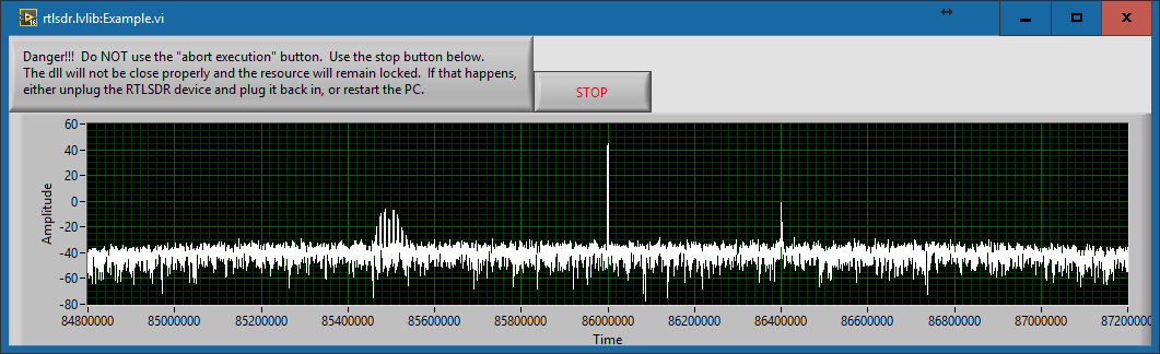
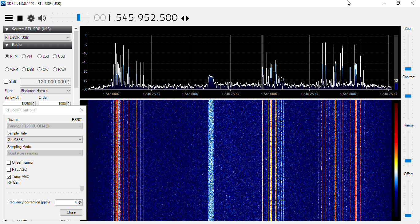
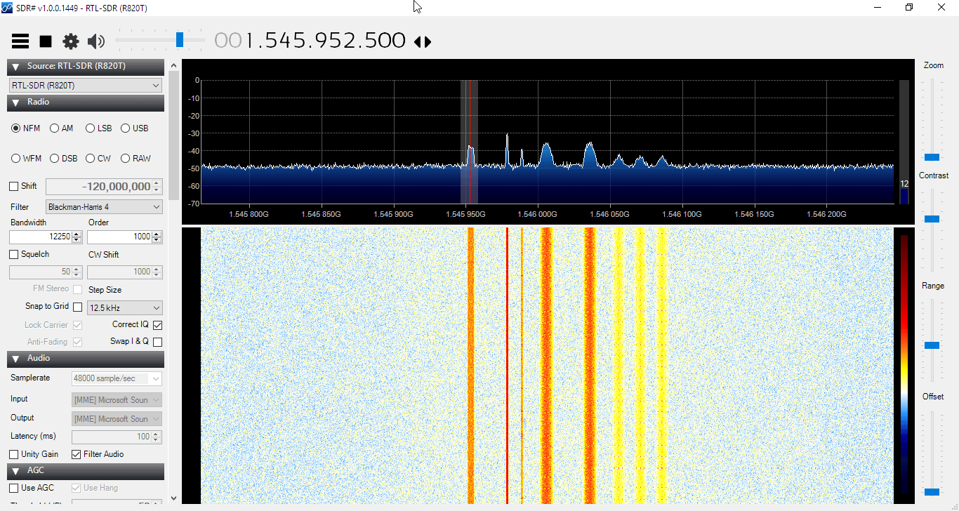
2) Lower internal noise. Less spurs, lower noise floor etc.
3) Software switchable bias tee. No need to do any soldering to enable the bias tee. Can be turned on and off in software.

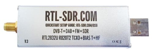
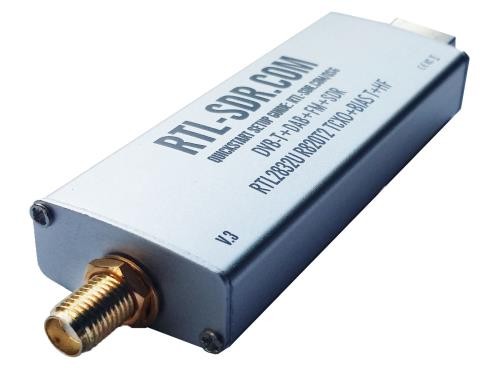
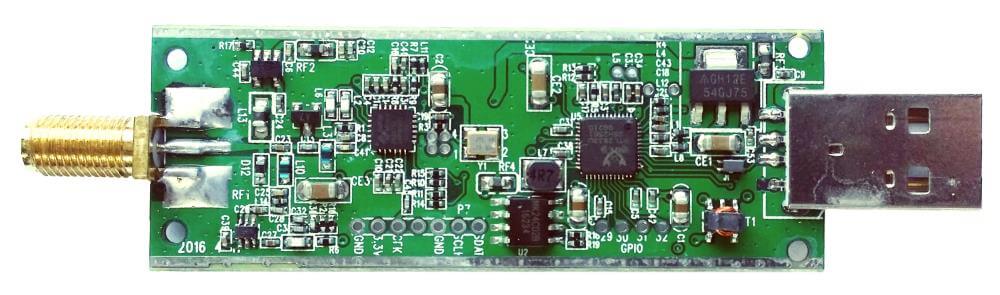
We call this version three of our RTL-SDR Blog dongles. The first was version zero and was simply the standard MCX dongles with better antennas. Next came version 1 with the bias tee and SMA connector, and version two introduced the metal case.

Here is the long list of improvements and changes, and why they were made:

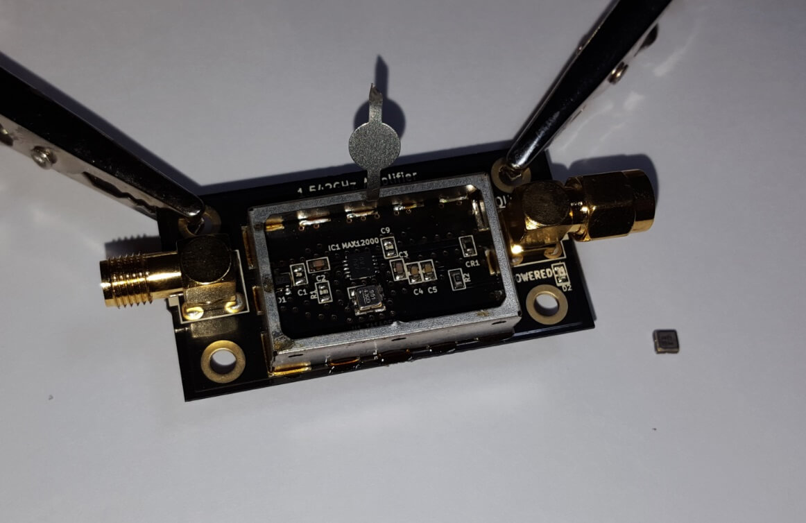
1) Improved ESD protection on the radio front end. The BAV99 diode which is used on most dongles is not a true ESD rated diode. We have added a real ESD rated diode for better protection. The BAV99 remains in the circuit as a strong signal clipper, to prevent damage to the R820T2 from overly strong signals. Please remember that not even this will save your radio from a lightning strike, and any permanently outdoor mounted antenna system must have its own lightning protection.

2) Longer SMA connector. One or two customers had problems with the shorter SMA plugs which could not fit some of their antenna connectors. The longer shaft fixes this and also allows us to add a nut to fasten it to the aluminum body which provides a better low impedance connection (although this is not strictly needed as the PCB side ground tracks already provide a good connection).

3) Improved front end circuit. The standard matching circuit on the RTL-SDR was designed for DVB-T use, and tends to attenuate signals above ~1 GHz. The new matching circuit has less attenuation above 1 GHz and similar performance below. We used very high quality, high SRF, high Q inductors in this circuit.

4) Added a software switchable 4.5v bias tee. In previous versions of our units the 4.5v bias tee needed to be activated manually, by soldering a bridge between two pads on the PCB. However we found that many customers who want to use the bias tee do not have the skills or tools to be able to perform this mod. The new unit makes use of a low noise LDO and one of the GPIO pins on the RTL2832U to activate the bias tee in software. This of course requires a modification to the drivers, but we will shortly upload a program called rtl_biast and batch files (available now) to turn the bias tee on and off in Windows and Linux.

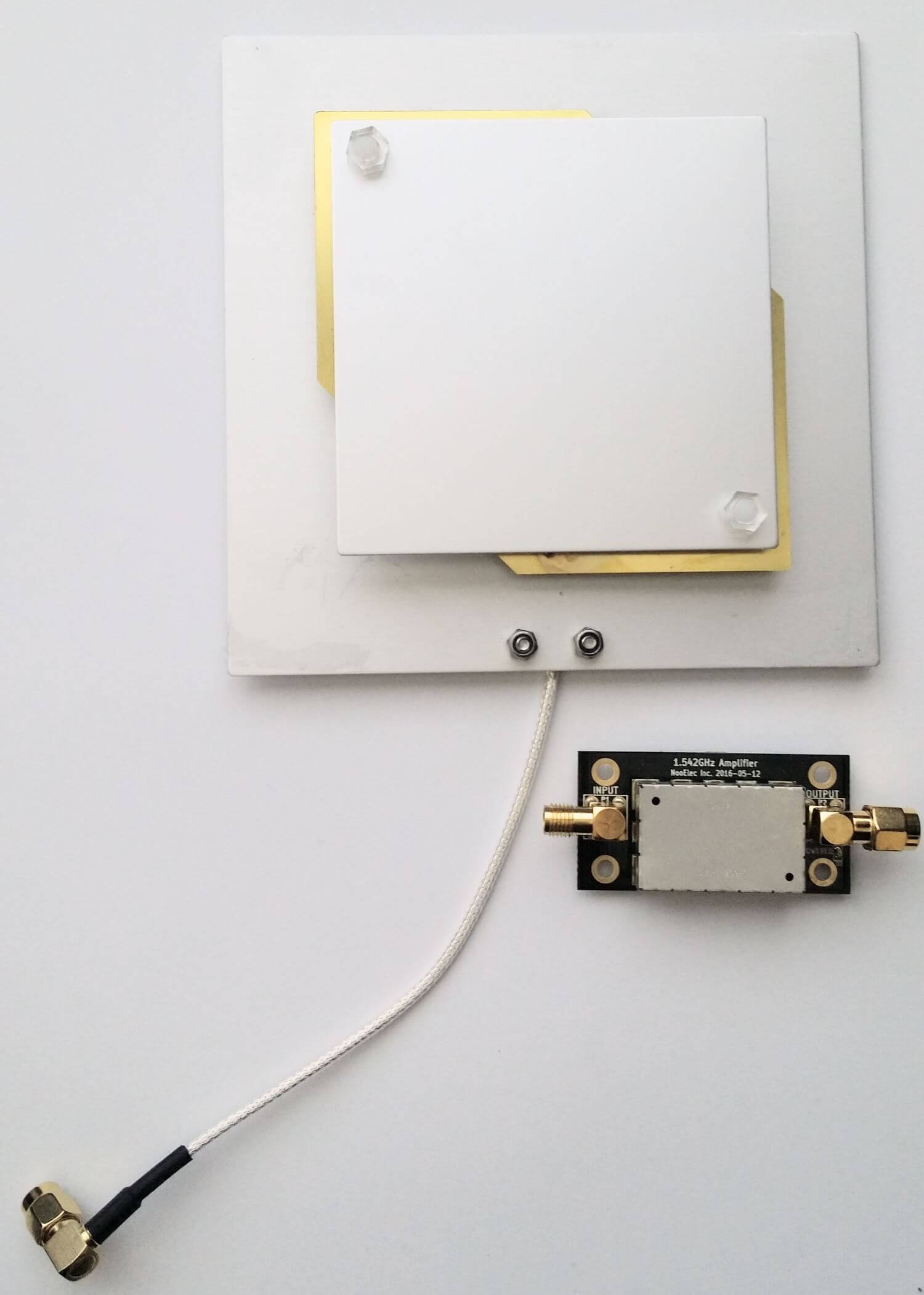
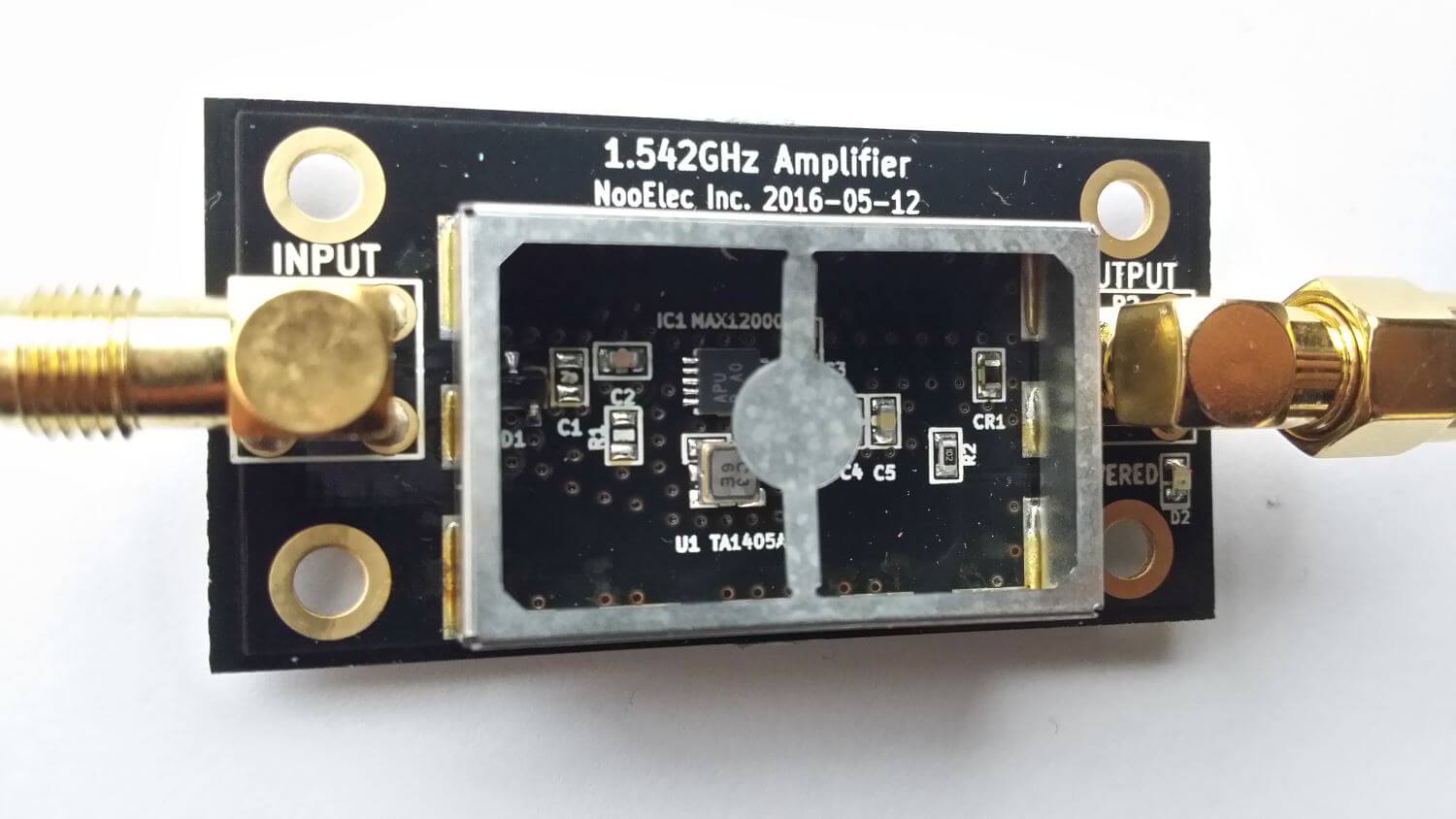
This bias tee is great for powering a remote LNA (like Adams PSA5043+ based LNA4ALL) or something like the SpyVerter upconverter. We’ve tested it with both and found them to be running just fine. 

Warning: The bias tee LDO can be damaged if you short circuit it. Before turning on the bias tee, ensure the circuit to be powered is not shorted, or that the RTL-SDR is not connected to a DC shorted antenna!

5) Added several access pads on the PCB. Access pads for the unused GPIO pins, CLK in/out, 3.3V, GND and I2C pins have been added. The CLK input/output is disconnected by default (see change 6). Access pads for the I branch have also been added as some users and industrial customers are using these in special projects. These pads are only for advanced users who need them for special projects. Take care as these pins are not ESD protected.

6) Added a clock selector jumper. By soldering in a 4 pin 1.27mm pitch jumper header and removing the default 0 Ohm resistor, one can now easily select between the onboard clock, an external clock, or having the on board clock be the output for another dongle. This is for advanced users only who want to experiment with things like passive radar, and coherent receivers.

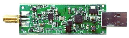
7) Reduced noise with a modified PCB design. This significantly reduces spurs and noise pickup due much lower impedance grounding and blocking of interference. Also added a USB common mode choke to reduce USB noise, several ferrite chokes on the PCB, and a lower noise LDO. A larger ground plane also improves on heat dissipation. 

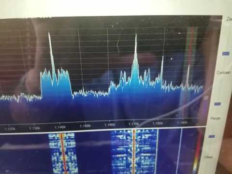
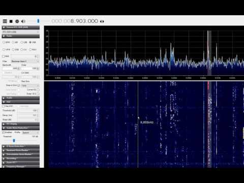
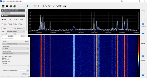
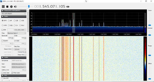
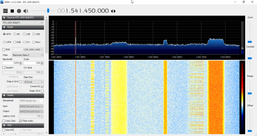
8) Added an experimental HF direct sampling circuit, which is diplexed out from the SMA connector. This has little to no effect on VHF/UHF operation, but allows us to make use of the Q branch on the RTL2832U chip for direct sampling, which allows us to receive from about 500 kHz to about 24 MHz. (Below 500 kHz is unavailable due to attenuation from the bias tee circuit). We used a ~10dB 50 Ohm preamp as a buffer and to overcome losses in the transformer and filter. We also added a strong 24 MHz low pass filter, and added an impedance matching transformer coil to ensure good direct sampling performance.

Of course direct sampling can never be as good as using an upconverter. It can overload easily if you have strong signals since there is no gain control. And you will see aliasing of signals above 14.4 MHz due to Nyquist. But this should at least give the majority of users a decent taste of what’s on HF. If you then find HF interesting, then you can consider upgrading to an upconverter like the SpyVerter (and the SpyVerter is of course compatible with our bias tee for easy operation).

We’re still classing this mode as experimental (and will be interested to hear any feedback on results), but we have had good results in our testing of this mode when receiving signals that are not too strong, getting sensitivity as good as an upconverter. We found that very good reception was obtainable with a long wire antenna and 9:1 unun combination.

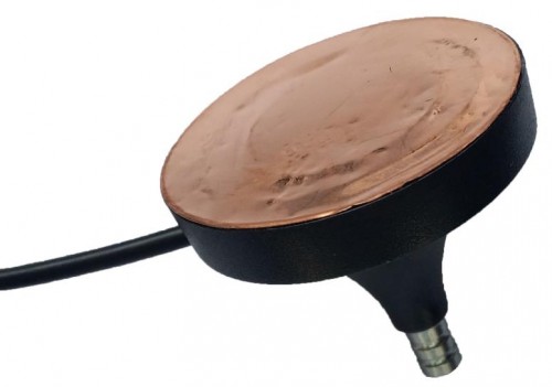
9) Antenna bases now come with a stronger magnet and a conductive copper sticker on the bottom. The stronger magnet adds very good stability when using our large 1.5m antenna and the copper sticker ensures that good electrical contact can be made between the base and whatever piece of metal you use underneath as the ground plane. This significantly improves the antenna’s performance as a quarter wave ground plane.

Ant_base_copper

10) Added corner mounting holes for those who want to stack PCBs. Some customers have been building devices that require multiple RTL-SDR dongles, and these standoff holes should aid in stacking.

As from the previous innovations the units still come with:

1) SMA connector – The most common connector in the radio world. Easy to adapt to other connectors and low loss over a wide range of frequencies.
2) Thermal pad – A thin thermal pad allows heat to transfer from the PCB to the metal case easily. The metal case then cools off to the surrounding air. This helps to solve L-band insensitivity problems.
3) Metal case – Helps block out interference and provides cooling.

We now have a V3 users guide available which explains how to use the new features such as the bias tee, HF mode and CLK jumpers.

What’s coming next?

We think that our unit is now pretty much at the peak of how good a cheap R820T2 RTL-SDR can be, so apart from minor tweaks this is likely to be our last major revision of this model of the RTL-SDR. In a 1-2 months we hope to bring out a FM bandstop filter with metal enclosure and SMA plugs with a target cost of $14.95 shipped. Further into the future we also hope to bring out supporting products like a wideband bias tee powered LNA and wideband antennas. These supporting products will of course be compatible with other SDR’s like the Airspy or SDRplay, or other RTL-SDR dongles.


RTLSDR_Profile