Hackaday Supercon 2024: Tracking Down Radio Transmissions
Talks from the Hackaday Supercon 2024 conference have recently been uploaded to YouTube, and one interesting talk by Justin McAllister and Nick Foster is about tracking down radio transmissions.
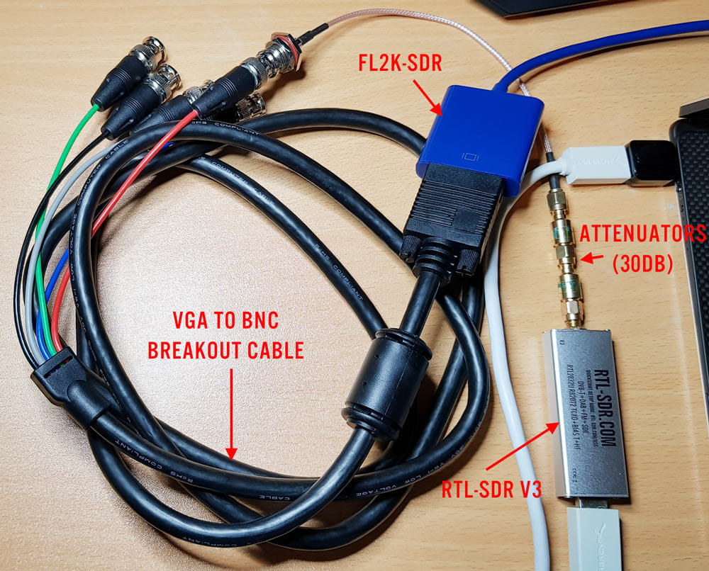
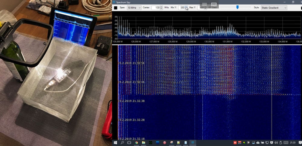
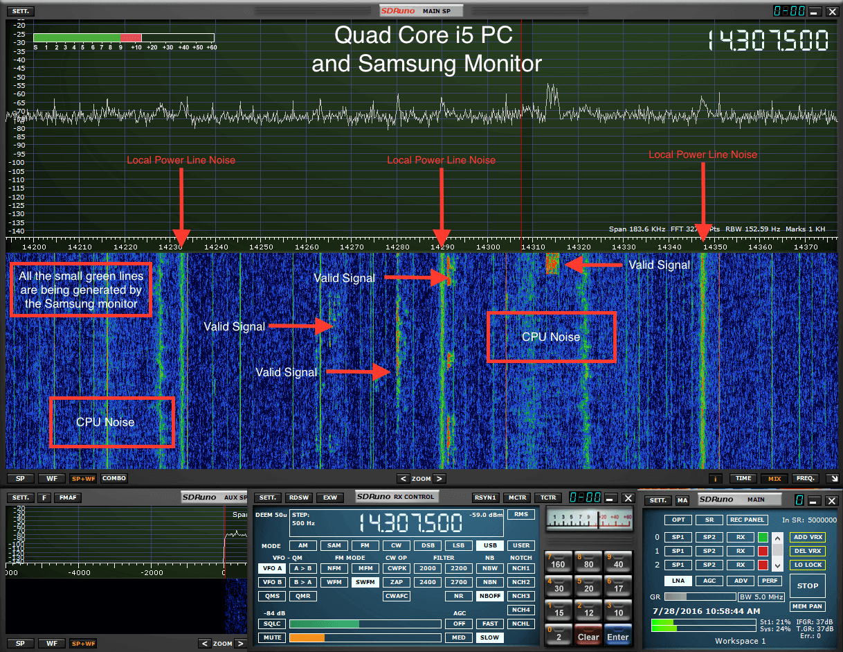
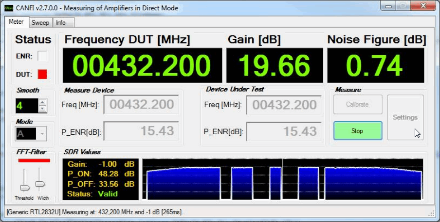
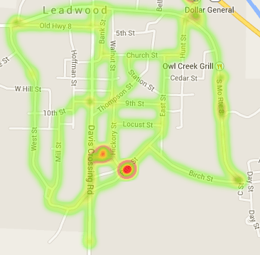
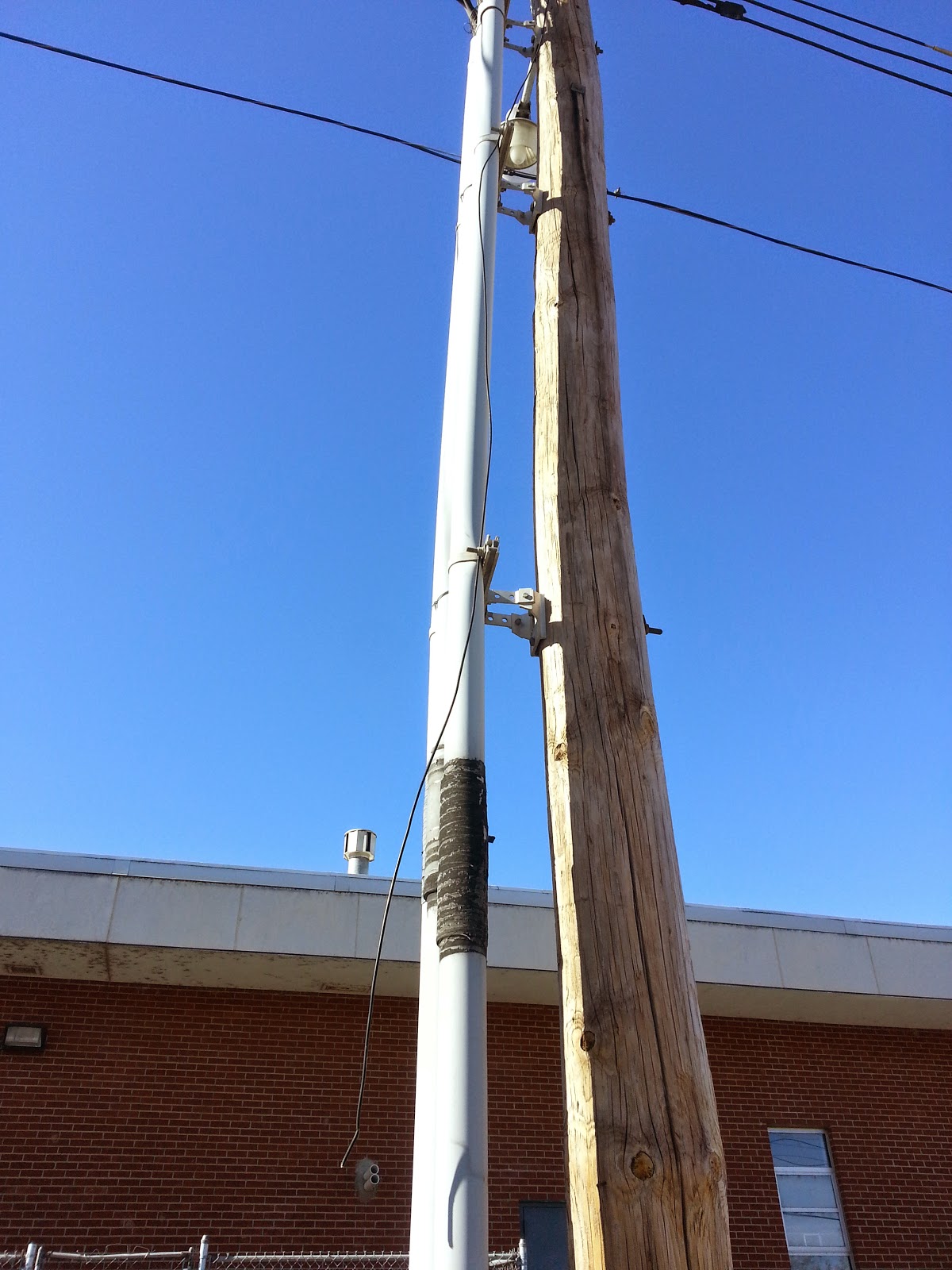
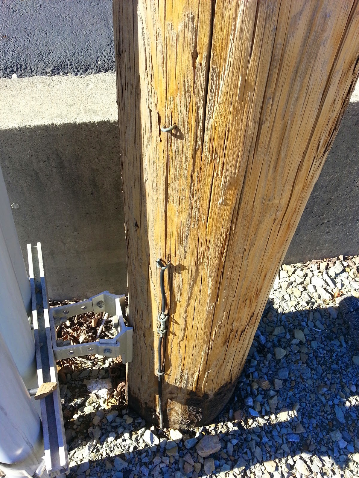
The talk focuses on using SDR hardware such as the RX888, RTL-SDR, and Airspy devices combined with directional antennas for radio direction finding. Interestingly, they also discuss using ultrasonic microphones to find power line noise from bad transformers or insulators. The talk also focuses on ensuring that your SDRs receive real signals and what noise might look like on the spectrum.
This talk provides a comprehensive guide to identifying and locating radio transmitters. Learn about practical techniques, common tools, and methodologies from decades of combined experience finding, squashing, and mitigating against radio frequency interference.