AirNav is the company behind RadarBox24.com, a flight data aggregation service similar to sites like FlightAware.com and FlightRadar24.com. RTL-SDR hardware is typically used to receive ADS-B, and like other providers AirNav have their own custom ADS-B optimized RTL-SDR unit. In addition they sell RTL-SDR's optimized for UAT 978 MHz and the VHF Airband. They also have a range of ADS-B/UAT/VHF airband outdoor antennas as well as filters.
Currently their products are discounted by 20% for Black Friday/Cyber Monday sales. The discount is available on Amazon, as well as directly from their store with coupon GET20.
The Search for Extraterrestrial Intelligence (SETI) is an ongoing project that aims to detect radio signals originating from intelligent species somewhere in the universe. Recently Alberto Caballero, a SETI researcher has been proposing a distributed search (project pdf document) with amateur and/or professional radio telescopes. The idea is that multiple stations around the world would monitor a single star for a period of time in order to collect data 24/7. To participate the requirements are a dish 2.1 meters or larger, a motorized mount, and a feed, LNA and radio system able to receive 1 - 4.5 GHz.
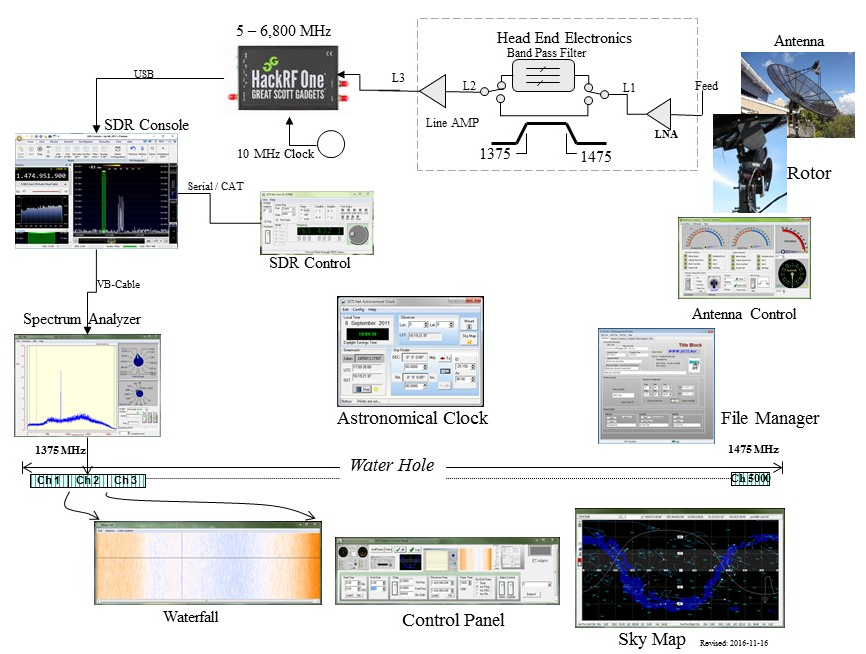
An example of a SETI station can be found at SETI Net. Here the owner has a 3M dish on a rotor connected to a HackRF. An LNA and band pass filter are also used at the feed end. SDR Console or SDR# is used to monitor a specific frequency, and the audio is sent into a special automatic SETI analysis program as well as spectrum analysis software. If an interesting signal is detected the software notifies the user, then further analysis can be undertaken.
If you have a suitable radio telescope available and want to participate, you can contact the SETI project via their contact form.
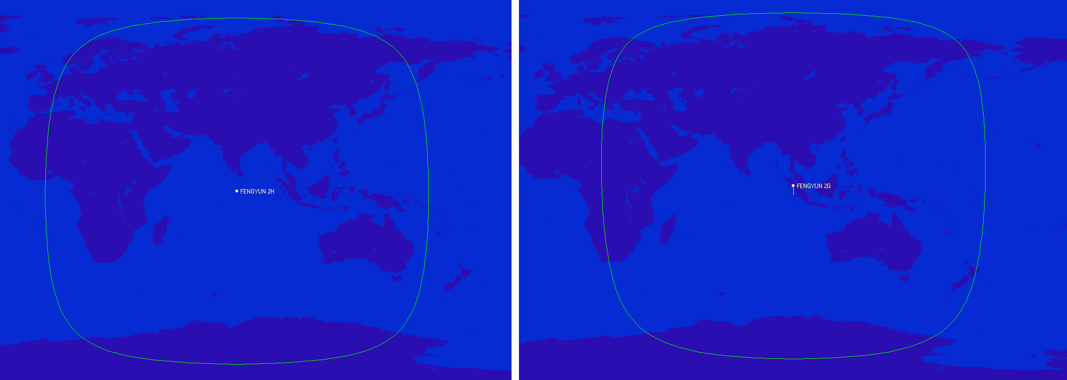
The FengYun-2 line of weather satellites are the Chinese equivalents to GOES, and they are positioned to cover parts of Europe, Africa, the Middle East, Asia, Russia, and Australia. So this is another geostationary weather satellite now available to Europeans which broadcasts in the L-Band at 1687.5 MHz. And unlike the weaker GOES-13 L-Band downlink, the FengYun-2 downlink is much stronger which means that reception with a 120cm satellite dish should be possible. We note that it has not yet been confirmed if the typical 90-100 cm WiFi dishes used with GOES-16 and 17 will be big enough to work. @aang254 writes:
Yesterday I successfully decoded the S-VISSR downlink from FengYun-2H thanks to a recording by @MartanBlaho. It is stronger than PDR on EWS-G1 (see Zbychu's signal https://twitter.com/ZSztanga/status/1329801728162754560…) meaning it should (untested) be doable with a 120cm (or smaller but no confirmation again) dish instead of 180cm.
It covers parts of Europe, Russia and down to Australia. FY-2G and FY-2E (no confirmation for this one yet) are also decodable in the same way. I released an early decoder, that currently is not suitable for automated setups but allows getting images already. A later version (that should come soon-ish) will allow live decoding / autonomous setups in a similar fashion to other satellites.
Also, the res is 2km/px on VIS and 8km/px on IR, so half that of GOES-13 with similar-ish coverage (Europe is less visible though).
(also forgot to say but the bandwidth is under 2Mhz, allowing a rtlsdr to be used)
Gave a go at a FengYun-2H animation with the data recorded by @MartanBlaho.
Sadly some scans focus only on the northen hemisphere but it still turned fine!
Visible channel pic.twitter.com/9FcZlD9oYi
Over on the Hackaday YouTube channel a video by Alex Whittemore has been uploaded showing how to do some basic RF emissions debugging. When creating electronic products it's important to ensure that there is no unintentional RF leakage in excess of emissions standards, and there is often a need to debug a circuit board to determine exactly what part or areas are generating excessive RF noise. To do this expensive EMC analyzers and near field probes are typically used.
Alex's tutorial video shows us how we can create a low cost home made EMC probe using an RTL-SDR, LNA and home made near field probe made out of magnet wire. The video starts by explaining RF compliance, demonstrating some higher end equipment, then moves on to showing how to build a probe yourself, before finally demonstrating it being used on some circuit boards. For software, he uses SDRAngel and QSPectrumAnalzyer which are preinstalled on a DragonOS image.
For some time now many weather satellite enthusiasts have enjoyed the ability to relatively easily receive live high resolution images directly from the GOES-16, GOES-17 and GK-2A geostationary satellites (tutorial here). However, while much of the world can see at least one of these satellites, European's have been left out.
What may be of some interest to Europeans is that the older GOES-13 (aka EWS-G1) satellite was repositioned in February 2020, and it can now be received in Europe (as well as Africa, the Middle East, Asia, Russia and West Australia) until at least 2024 when it will be replaced.
The important catch however is that GOES-13 is not broadcasting the same easy to receive LRIT/HRIT signals that the other satellites use. The signal is still in the L-Band at 1685.7 MHz, however it is called "GVAR" and it is much weaker and uses 5 MHz of bandwidth. For GOES 16/17 and GK-2A a 1m WiFi grid dish, LNA and RTL-SDR was sufficient, but for GOES-13 you'll need a much larger 1.8m dish, and a wider band SDR like an Airspy. The big dish requirement significantly increases the reception challenge.
We also note that the decoder is being developed by @aang254 and u/Xerbot and it is not yet publicly released. However, they do intend to release it soon. Update:
My hardware is: 180cm prime focus dish, with a custom cantenna (120mm diameter). I'm using the SAWBIRD GOES LNA. I will be switching to the + version, because the setup is still lacking a few db SNR. The SDR is the one I use for HRPT: the airspy mini
I found that the USB connection on the airspy generates a lot of noise, so I removed the USB cable, by moving the airspy to the laptop. I use 2m of CNT-400 coax and it works much better now. I get about 2 db SNR more. Thought you might find it interesting.
@ZSztanga's GOES-13 Reception Setup, with 1.8m dish.
We note that there is some interesting differences with GOES-13 images. Since the image is less processed, it is higher resolution (a full resolution image can be found on this Reddit post), as well as not cropped, meaning that the Earth's atmosphere is visible. Please also follow @ZSztang on Twitter for more images.
According to the newest calculations performed (by me) on the EWS-G1 data, it has a stunning resolution of about 0.6x1 km/px on the VIS channel and about 2.5x4 km/px on the IR channels. I have yet to confirm my calculations with the doc, which is quite hard to get. pic.twitter.com/kLK8YPDyTV
What I really like about GOES-13 is that the data is unprocessed. That allows to see the atmosphere which is normally cut off on LRIT/HRIT. pic.twitter.com/BWJAVXFnUi
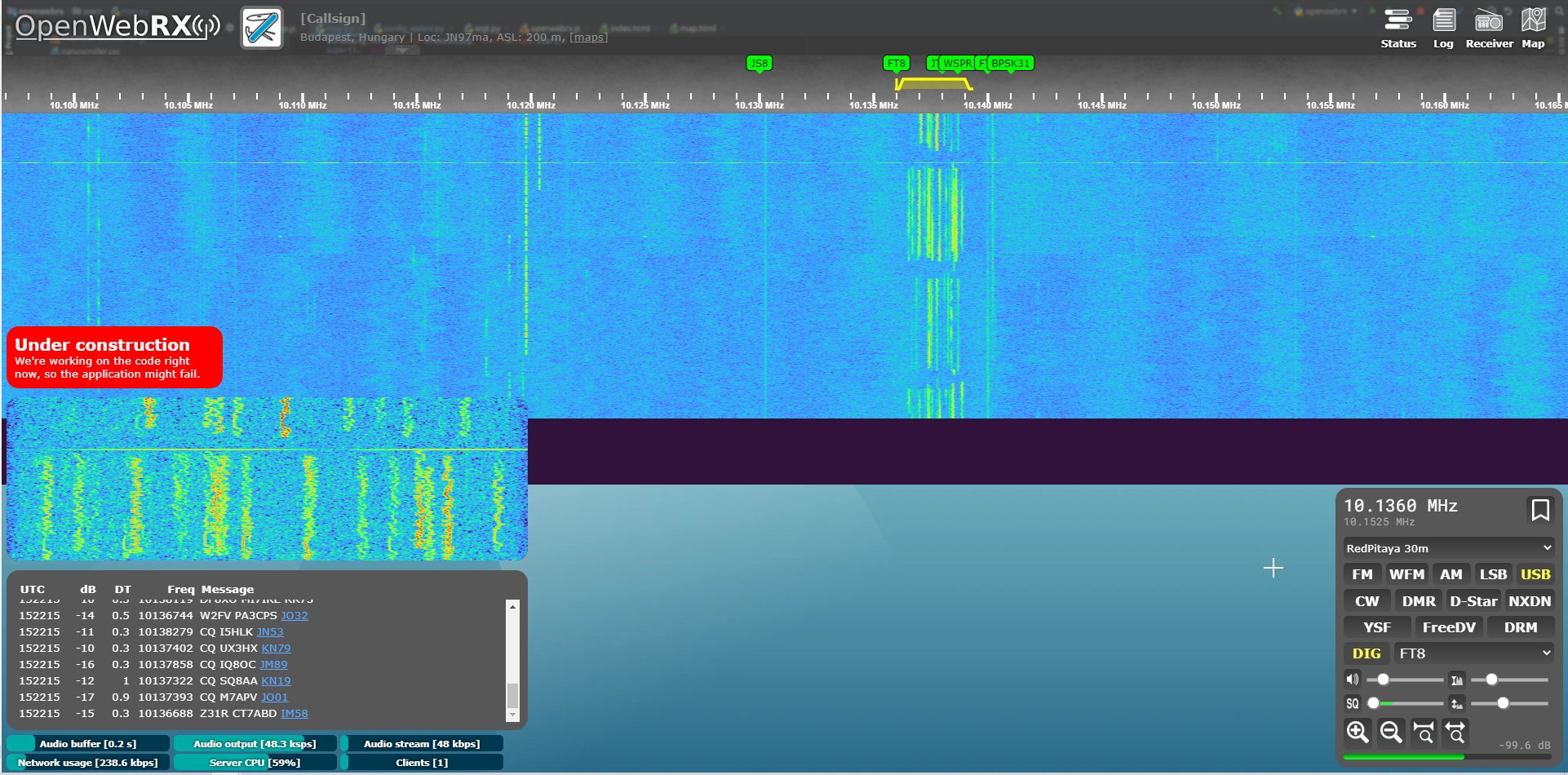
Thank you to Stefan Dambeck (DC7DS) for submitting news about OpenWebRX adding support for Hermes HPSDR compatible SDRs. Hermes is a single board version of the open source high performance SDR (HPSDR) design. There are several compatible Hermes designs including the newer Hermes-Lite 2 . The Red Pitaya is an open source electronics laboratory instrument, but custom software can be installed allowing it to function as an HPSDR type SDR. OpenWebRX is software which allows you to access your SDR remotely via the internet or local network through a web browser. Stefan notes:
I built a test setup today using a Red Pitaya 125-14 SDR in HPSDR mode, and this is now also supported, see screenshot.
At the moment, only one receive stream is supported, for the red pitaya with 192KHz bandwidth.
If you weren't already aware KerberosSDR is our 4-channel phase coherent capable RTL-SDR unit that we previously crowdfunded back in 2018. With a 4-channel phase coherent RTL-SDR interesting applications like radio direction finding (RDF), passive radar and beam forming become possible. It can also be used as four separate RTL-SDRs for multichannel monitoring.
A single KerberosSDR combined with an antenna array is able to determine a bearing towards a signal source. By using multiple KerberosSDR units spread over a large area it is possible to triangulate the location of a transmitter and display it on a map. Corey's software uses a modified branch of our open source KerberosSDR code in order to generate a modified XML page that the mapping software polls for updated data. Some instructions on it's use are available on our forums and on the GitHub.
The image below shows three KerberosSDR stations on the map, and two transmitter locations that have been triangulated using the bearings from the three distributed KerberosSDR units.
Over on GitLab Josh Conway has released a design for an automatically adjusting antenna array which can be used with radio direction finding capable SDRs like our KerberosSDR. KerberosSDR is a SDR consisting of four RTL-SDRs connected to the same oscillator, a USB hub, a built in noise source and calibration hardware which allows software to use the four RTL-SDRs coherently. Coherent operation of SDRs enables interesting applications such as radio direction finding, passive radar and beam forming.
With coherent antenna array based direction finding, the optimal spacing between the antenna elements is proportional to the wavelength of the frequency being received. If you want to do RF direction finding on different frequencies, either multiple antenna arrays with different element spacings, or manually adjusting the antenna array with each frequency change is required.
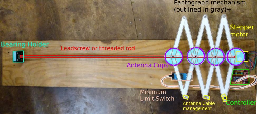
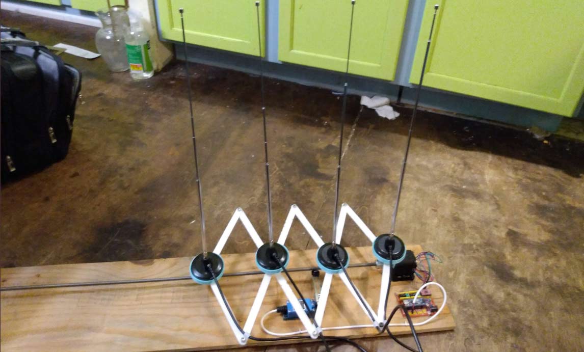
Josh's design automates this problem with an antenna array that can adjust the spacing automatically. The design puts the antennas on an extending pantograph arm whose length is controlled via a threaded rod connected to a stepper motor. An Arduino microcontroller controls the stepper, thus allowing the spacing to be adjusted automatically.
A Pantograph Antenna Array for Direction Finding
A full description of the build is provided in the document on GitLab titled "provisional_patent_application.pdf". From Twitter it appears that Josh (@CrankyLinuxUser) was unable to secure a patent for this design, so he has released the design for free under AGLP3. Most of the parts are 3D printed, and the CAD stl files all appear to be available on the GitLab. The Arduino microcontroller firmware is also available.