Recently, SunFounder sent us a free review unit of their latest "Pironman 5 MAX" enclosure for Raspberry Pi 5 devices. While not directly related to SDR, we thought we'd accept the unit and review this product, as RTL-SDRs are often used together with Raspberry Pi 5 single-board computers. Depending on the number of SDRs connected and the software used, SDR applications can consume a significant amount of CPU, causing heat and throttling down of CPU speeds; therefore, adequate cooling may be necessary.
The Pironman 5 costs US$94.99 if purchased directly from the SunFounder website, and they advertise that US duties and EU VAT are included in the pricing. There is also the slightly lower Pironman 5 model available for US$79.99. The main difference between the 5 and 5 MAX is that there is only one SSD expansion slot vs two on the 5 MAX, and no tap-to-wake OLED functionality.
Overview
The Pironman 5 is what we would consider a high-end enclosure for the Raspberry Pi. It includes a large CPU tower cooling heatsink with a fan, along with two case fans to keep the internal temperatures down.
It also adds a dual slot NVME M.2 expansion board to the Pi 5, so that you can install two SSDs or one SSD and a Hailo AI accelerator module. SSDs might be useful for RTL-SDR users who are recording large amounts of IQ data, or saving many weather satellite images, for example. The Hailo AI accelerator module could turn a Raspberry Pi and RTL-SDR into an RF intelligence powerhouse. One advanced AI use-case might involve running local Whisper speech recognition to log voice communications to text, followed by using a local LLM to summarize daily received data (noting that you'll need to wait for the Hailo-10H model to run local LLMs).
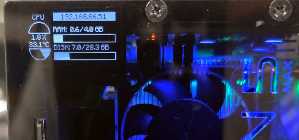
Finally, it also adds an OLED status display, which shows current CPU temperature and fan speeds, as well as an on off button.
Another plus is that the GPIO header remains accessible on the outside of the enclosure, thanks to an extender included in the design.
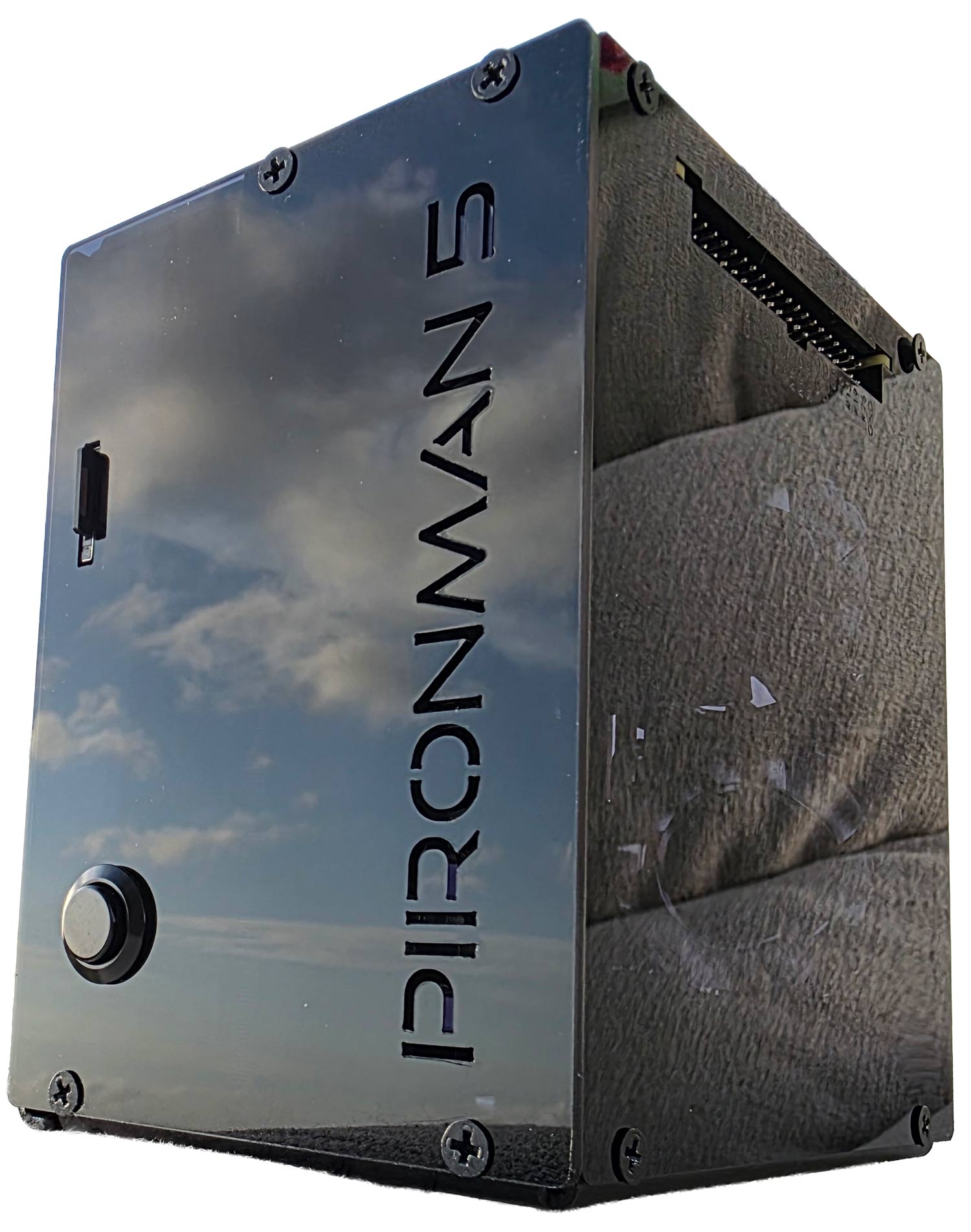
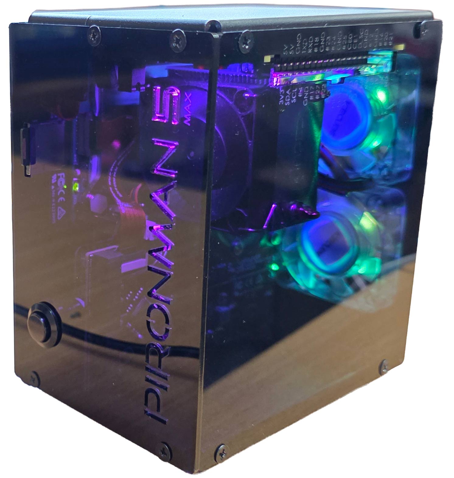
Pironman 5 Fully Assembled
Assembly
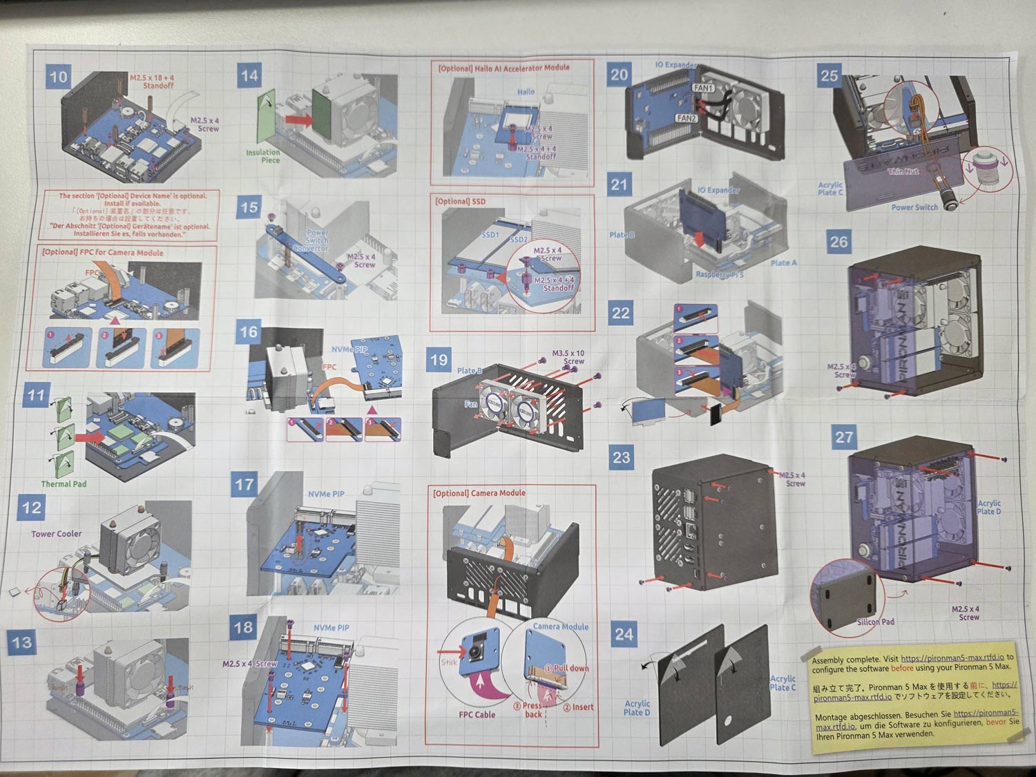
Assembly of the Pironman 5 took just over 30 minutes. It involves screwing in standoffs, seating the heatsink/fans, connecting jumpers and ribbon cables, and screwing down the panels. A nice color paper assembly manual is provided, making the installation easy to follow. Anyone who is mildly familiar with installing connectorized PC components should have no trouble.
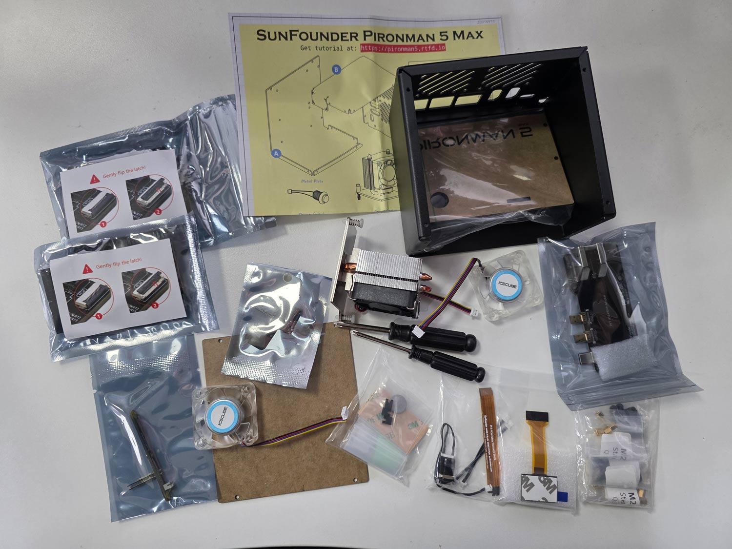
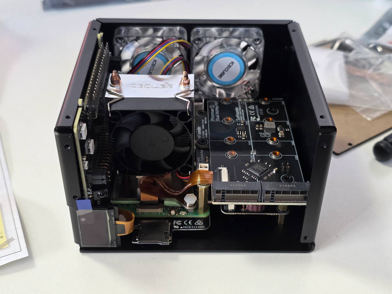
All parts included with the Pironman 5.Pironman 5 Assembly ManualPironman 5 Built (Acrylic side panels off)
Software Installation and Usage
After assembly, you can simply insert a freshly burned Raspbian image into the SD card slot and power on the unit.
At this stage, you now need to install some software to properly control the OLED, CPU fans, and case fans. This involves installing some software from their GitHub, but you can simply copy and paste the commands in the terminal one by one.
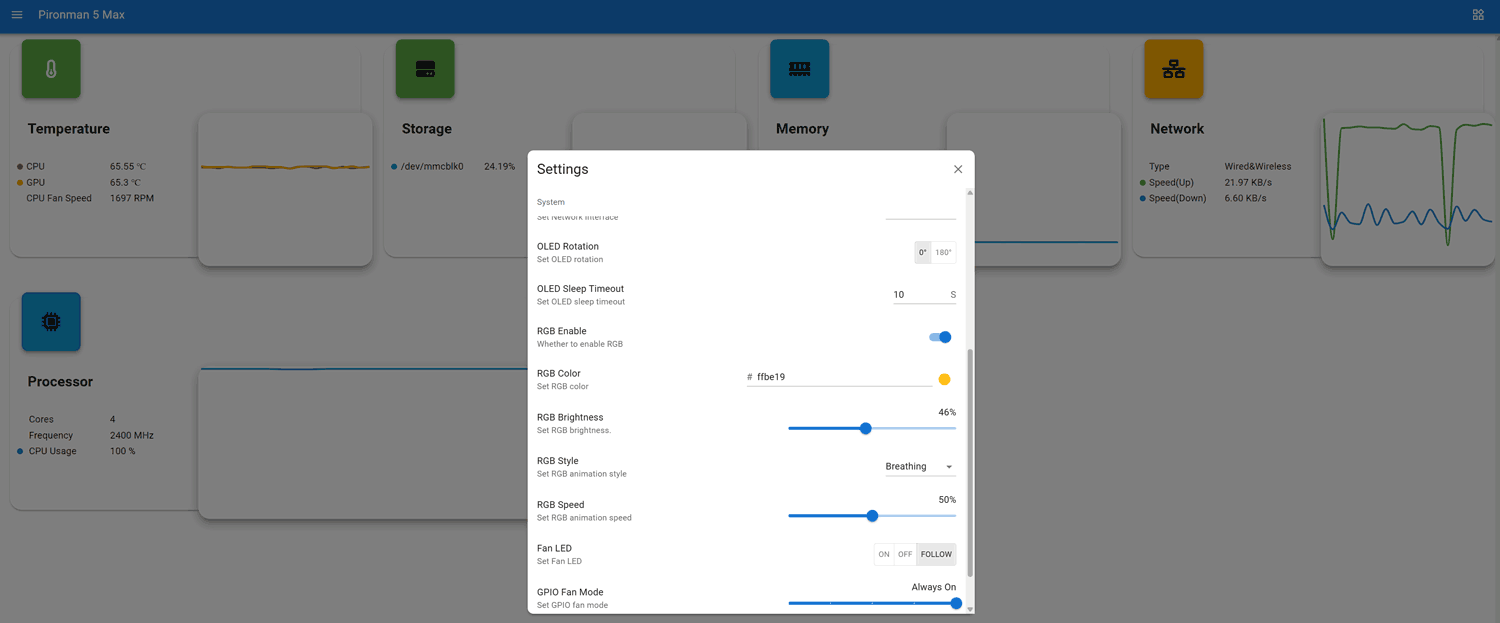
Once the software is installed a web UI is exposed at <IP_ADDR>:34001. Here you can monitor various stats including CPU temps, and make changes to the OLED, RGB and fan behaviour.
Pironman 5 Web UI
OLED QC Problems?
Unfortunately, our unit had a problem where the OLED screen wouldn't work. We attempted fresh software installs and reseated all cables and connectors, but had no luck. Upon contacting SunFounder, they immediately sent us a new OLED screen to try. But the replacement also did not work.
However, when trying the new screen, we noticed that the screen would briefly light up when we pressed on the FPC connector. Upon inspecting the FPC connector, we noticed that some pins on the PCB looked suspiciously low on solder compared to the others, so we applied flux and used a hot soldering iron to refresh them. After doing this, the OLED screen began working again.
Based on our dealings with SunFounder, we believe that they're support is good, and any customer facing similar issues would be supplied with replacement parts if required.
Pironman OLED Screen Working
Usage and Performance with RTL-SDR
As expected, with the great cooling in place, the Raspberry Pi 5 never throttled down when running an RTL-SDR with SDR++. We also tested it with our KrakenSDR system, which requires more CPU, and found great performance too.
The rear GPIO fans are quiet enough, and the CPU fan makes almost no noise inside the enclosure. We ran a stress test using the 'stress' Linux package, which can push all four CPU cores to 100%. With the fans running in a room with an ambient temperature of 22 degrees, we saw that the CPU temperature never went above 55 degrees C.
While still running 'stress', we manually disabled the two GPIO fans, and the temperature stabilized at around 66 degrees C. So the rear fans may only be required to be on when you have an SSD or AI module installed.
Conclusion
If you're looking for a high-quality enclosure and cooling solution for the Raspberry Pi 5, the Pironman 5 MAX is probably the best high-end solution available. Not only does the enclosure protect the Raspberry Pi 5 completely, but the cooling performance is excellent, and the ability to add SSDs and AI modules is great too.
Disclaimer: We were given a unit for free in exchange for an honest review. We received no other compensation.
As mentioned in a previous post last week, UUGear have recently released their VU GPSDR expansion board for their Vivid Unit single board computer with touchscreen. Together, this combination results in a handheld Linux system, with built-in RTL-SDR and upconverter.
The VU GPSDR has some interesting features, including:
GPS-assisted 24 MHz clock for improved frequency accuracy and stability
An integrated 108 MHz up-converter for HF (under 30 MHz) reception
Dual programmable rotary encoders for tactile control
A software-controlled frequency output port for experiments
Software features, including OpenStreetMap integration and ADS-B aircraft tracking
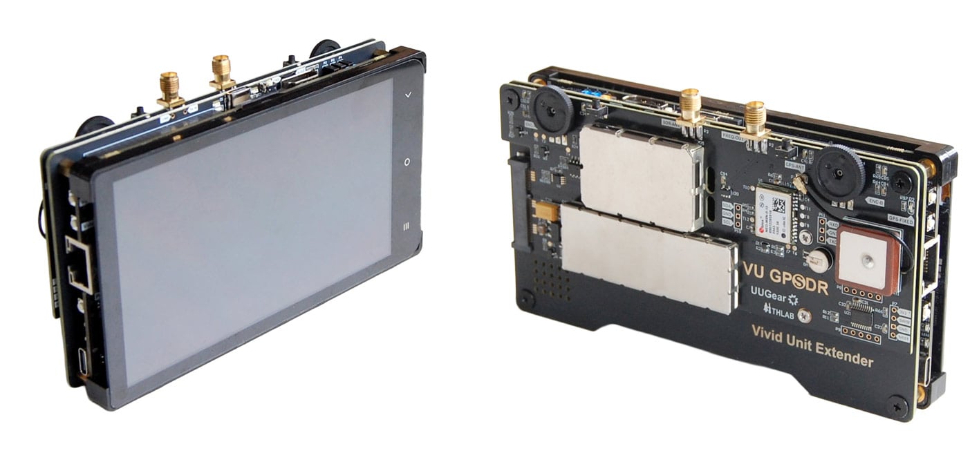
Vivid Unit with VU Extender and VU GPSDR
Assembly
We won't repeat the assembly steps as the instructions show everything clearly, but we can say that the assembly steps were clear, and the assembly itself was easy. It was simply a case of plugging in a few jumper wires between the Vivid Unit and VU Extender board, screwing down the extender board, and then slotting in the VU GPSDR into the Extender boards mini-PCIe slot, before finally screwing down the GPSDR. Assembly took less than 10 minutes.
Physical Design Review
The system is put together like a sandwich. You have the screen and Vivid Unit on the top, then the Extender board, and finally the VU GPSDR on the bottom.
The Vivid Unit and GPSDR are essentially bare PCBs that connect to one another via the PCIe slot on the Vivid Extender board. This means that there is no enclosure, and you are essentially handling PCB parts in their raw form. In the future, we would like to see an optional enclosure to protect the unit better.
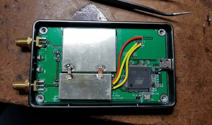
The exposed design results in some flaws that we have to point out. The shielding cans on the VU GPSSDR unit sit on the rear of the system, and during operation, they get very hot to the touch. So much so that handling the unit requires a bit of care to avoid the hot spots. Most of the heat appears to be coming from the AMS1117 LDO on the rear, which gets up to 80 °C, so be careful not to touch it accidentally. From the photos you can see that the RTL2832U and R860 are heatsunk to the shield. This is a good idea to keep the chips cool, but it also means that the metal gets quite hot to the touch. So handling the unit only from the edges is recommended.
Vivid Unit with the shielding cans removed.VU GPSDR Thermals
Secondly, because the Vivid Unit does not have a built-in battery, you need to power it separately via its USB-C port on the side. This makes the ergonomics of handling the unit a little trickier as you also have a cable sticking out. UUGear has noted that they are working on an 18650 battery pack, so this issue may be resolved in the future.
Finally, the "GPS" in the GPSDR comes from the fact that there is a GPSDO with a built-in GPS patch antenna on board. When active, a GPSDO provides excellent frequency stability, meaning that signals will be on frequency and will not drift.
But because of how the system is designed, the GPS patch antenna faces the ground when you look at the screen, even though it should face upward to get a clear view of the sky for satellite signals. However, despite this, we were happy to see that even while upside down, the patch antenna was able to receive several GNSS satellites with sufficient strength in order to obtain a fix when used outdoors.
Indoors, of course, no GPS fix is possible. But the uBlox NEO-M8N GPS module used in the GPSDR also has a fallback TCXO, so even without any GPS fix, the frequency accuracy of the system is good. UUGear also noted that the GPSDO automatically activates once a GPS fix is achieved, so no action is needed when you take the unit outdoors.
Realistically, the design issue with the GPS patch doesn't really matter anyway. For most use cases in handheld operation, the built-in TCXO will be sufficient. Any use case requiring extreme GPSDO precision will probably involve the device being mounted upside down and used remotely.
The screen is clear and bright, the two encoder wheels are non-indented and are in a good spot, and so is the SMA antenna port, although the VU Extender's USB-C plug can block the antenna SMA port if a really fat plug is used (normal-sized USB-C plugs fit OK). The screen is large and has a high resolution, making it possible to use the onscreen keyboard. However, it is still a little fiddly for typing and clicking, so we ended up plugging in a small wireless keyboard.
HydraSDR is a soon to be released software-defined radio based on the same design as the popular Airspy R2 SDR. However, compared to Airspy, HydraSDR claims to have "Enhanced PCB layout and RF front end with superior power/noise filtering, improved temperature dissipation and peak temperature management," as well as various other improvements. HydraSDR also has the distinction of being made in the USA, whereas Airspy is made in China.
Recently, Benjamin Vernoux, creator of HydraSDR and former collaborator on the Airspy R2 project, sent us a review unit of the HydraSDR. This post is a review of the HydraSDR. However, because the HydraSDR is based on the Airspy R2 and competes directly with it, the two units will be heavily compared.
The design of the HydraSDR is very similar to the Airspy R2, which is already known to be a high-performing SDR. Both are based on the LPC4370 microcontroller and its built-in ADC, and they both use similar firmware. The circuit layout, from the top and bottom views, is also almost identical. Benjamin notes that the internal layout has been improved and that several components, such as LDOs, have been upgraded to better ones with reduced noise.
One larger change is that HydraSDR uses a Rafael R828D tuner, instead of the Rafael R860T tuner that the Airspy uses. Both tuners are very similar in terms of operation and performance as they are based on the same design and technology. The R828D has two additional RF input pins; however, on the HydraSDR, they are unused but are routed to two uFL connectors on the bottom of the PCB for advanced users.
Airspy (Top) and HydraSDR (Bottom) PCB Top SideAirspy (Top) and HydraSDR (Bottom) PCB Bottom Side
Both the HydraSDR and Airspy come in a black anodized aluminum extruded enclosure. The Airspy's enclosure is more compact, but the HydraSDR enclosure is purposely oversized to accommodate up to three HydraSDR PCBs.
However, additional holes for two extra SMA ports and two extra USB-C ports have not been pre-drilled, so we assume the 3x unit may be a separate product coming out in the future. The HydraSDR also utilizes an SMA port for the optional CLK-IN port, unlike the MCX port on the Airspy.
Airspy (Left) and HydraSDR (Right) Side Profile
A major win for the HydraSDR is its use of a USB-C connector, whereas the Airspy R2 still uses a micro USB connector. (We note that it is a USB-C connector, but not USB3.0, it is still USB2.0).
The microUSB connector on the Airspy R2 is less robust and can easily disconnect if bumped, even with brand-new cables. The connection on the HydraSDR is rock solid, and no amount of reasonable bumping of the cable can disconnect it.
The HydraSDR spec sheet also mentions its suitability for phase-coherent applications, such as radar. However, although you can run all three from the same clock, from what we can see, specialized firmware, software, and external signal and/or noise source hardware would still be required for sample and phase alignment, as the system can not be naturally coherent. We're unsure whether the company will be directly supporting coherent use cases or if coherence is left as an exercise for the customer.
Software
Both Airspy and HydraSDR use the same USB VID/PID identifiers, so most software should recognize them as the same device.
We decided to see if it would run in SDR#, the official software of Airspy. Upon selecting the device as an Airspy R2 in SDR#, we were able to see it work and operate just like a genuine Airspy R2. We want to note that Youssef has mentioned that, in his view, using non-Airspy products like the HydraSDR with the Airspy source would be in violation of SDR# terms, but we will use it in this review for comparison purposes.
HydraSDR Running in SDR# as an Airspy R2 Device
This is interesting because in SDR++, the software recommended by HydraSDR, selecting Airspy R2 as the device results in the device being unable to connect. Currently, SDR++ does not support HydraSDR in its latest releases; however, support is being developed.
For now, until SDR++ officially supports HydraSDR, Benjamin has released a custom fork of SDR++ that will be available on the HydraSDR website.
HydraSDR Running in SDR++ (HydraSDR Fork)
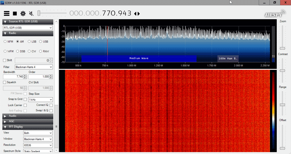
We note a few differences between SDR++ and SDR#. SDR# restricts the visible bandwidth of Airspy devices to 8 MHz, as this hides the edges, which contain aliased signals. SDR++ does not hide the sides. SDR# also has an 'HDR' (high dynamic range) mode for Airspy devices, whereas SDR++ does not. More on HDR mode is discussed under the testing heading.
When HDR mode was turned OFF, no differences in performance between SDR# and SDR++ were noticed.
We are also aware that HydraSDR is now supported by gr-osmosdr (GNU Radio source block), SatDump (satellite decoding software), and URH (Universal Radio Hacker).
We also found that HydraSDR runs as an Airspy in SDR-Console V3. Official Airspy software, such as SpyServer and adsb_spy, also work with HydraSDR. We suspect that most software that supports the Airspy will be compatible.
Testing
No Antenna Test
In this test, we connected each SDR to a dummy load and used SDR# to look for signals. If the SDR is shielded well, no signals should be received.
We noticed that the HydraSDR has excellent shielding and is very well protected against signals entering through paths other than the antenna. The Airspy was able to receive a strong TV channel without any antenna, indicating that it has shielding issues.
HydraSDR (Left) Airspy (Right) No Antenna Connected
Across the spectrum, the HydraSDR also has a cleaner spectrum with lower power levels on most internal spurs.
Real World SNR Tests
In this test, we received real-world signals with each SDR connected to a roof-mounted Discone, which was in turn connected to a splitter. We increased the gain settings to optimize each SDR for best SNR, which is typically just before it overloads and creates images.
We noticed that the gain distribution on the HydraSDR was slightly different from that of the Airspy, as the HydraSDR would overload on a lower gain setting compared to the Airspy. When optimizing for SNR we found that a gain setting 1-3 notches higher on the Airspy was required.
Once optimized, we found that results were very similar, with a slight 0.5 - 1 dB sensitivity edge going to the HydraSDR; however, this may be within chip-to-chip variances, so we can't say for certain if one is more sensitive than the other.
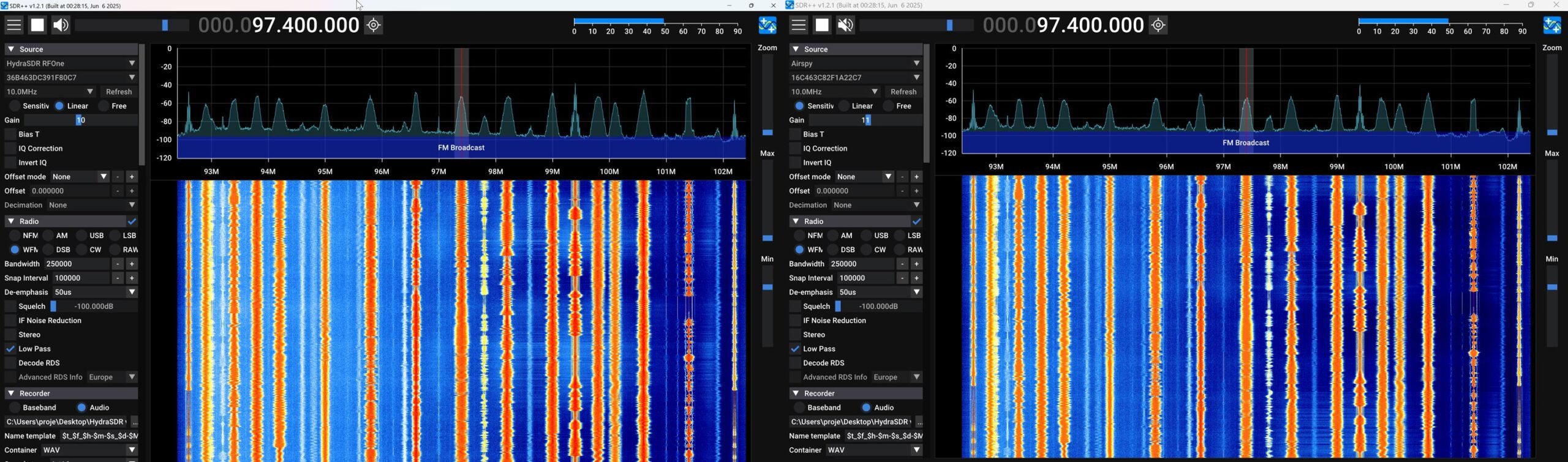
HydraSDR (Left), Airspy (Right). Same SNR on BCFM in SDR#HydraSDR (Left), Airspy (Right). Same SNR on BCFM in SDR++HydraSDR (Left), Airspy (Right). Slightly better SNR for the HydraSDR at 457 MHz.
Real World Comparison SDR++ vs SDR# 1921
HydraSDR recommends using SDR++, whereas Airspy recommends using the Airspy native software SDR#. While HydraSDR currently works on SDR#, we're not sure if this will continue, as SDR# could possibly block the use of clones and spinoffs. So, it seems fair to compare HydraSDR with SDR++ and Airspy with SDR#.
Under normal operation, with moderate strength signals, both programs appear to give nearly identical performance in terms of audio quality and signal SNR.
However, Youssef has pointed out that SDR# (and SDR-Console) has a special mode called HDR (high dynamic range) available for Airspy products. HDR mode works by optimizing the DSP chain specifically for the Airspy hardware whenever decimation is used. With HDR mode on, we can push the gain setting much higher than we would have otherwise without experiencing overload, resulting in a better SNR.
We are currently aware that only SDR# and SDR-Console V3 implement the Airspy HDR mode tweaks, and SDR++ does not.
Comparing performance between two different programs can be a bit tricky because each uses a slightly different FFT algorithm, resulting in different SNR values being calculated. SDR++ consistently calculates a somewhat higher SNR for the same signal.
To illustrate the effect of the Airspy HDR mode, we will use two SDR# instances and disable HDR mode for the HydraSDR, simulating the effect of using it in SDR++, which does not have HDR mode.
HydraSDR with HDR Mode OFF (Left), Airspy (Right) HDR Mode ON
This test showed a rather dramatic +7 dB improvement with HDR mode on. With HDR mode on we were able to increase the gain much further without overload. In the screenshot we increased the gain as far as possible to optimize the SNR on each receiver as much as possible.
For an audio comparison that directly compares Airspy on SDR# vs HydraSDR on SDR++, here is an audio file of the Airspy running SDR# with HDR mode ON, 16x decimation, receiving a weak signal sandwiched between strong signals.
And here is the audio file of SDR++ with 16x decimation receiving the same signal.
Both signals were optimized for the best SNR possible which was just before the SDRs overloaded and displayed intermodulation products. There is a clear difference in audio quality that can be heard, with SDR # emerging as the winner. Note that these HDR improvements may only be seen in a high dynamic range environment (when strong signals are mixed with weak signals) and when decimation is used .
Conclusion
With the Airspy R2 starting to feel a bit dated, the HydraSDR looks to be a great addition to the choice of available SDRs. However, we consider it to be essentially a spinoff of the Airspy with some minor changes made to improve performance and usability. The improved shielding and USB-C port are particularly notable enhancements that we love. Compared against the Airspy, HydraSDR is clearly the better hardware choice.
But if you already have an Airspy R2, there are not enough improvements here to consider the HydraSDR as a next-generation upgrade worth purchasing. That said, if you're looking for a new SDR made in the USA, the HydraSDR should be on your radar.
The Airspy maintains some software advantages, such as official software support and compatibility with SDR#’s and SDR-Consoles HDR mode, which excels in strong signal environments. However, the HydraSDR is directly compatible with the Airspy and currently functions as one in SDR#, allowing it to benefit from HDR mode as well. But this compatibility relies on SDR# not actively blocking it. It's also important to note that Youssef has mentioned that, in his view, using the HyraSDR in SDR# would be in violation of the SDR# licensing agreement, as would loading the HDR enhancements in SDR-Console V3 with HydraSDR (note that we have not verified the legality of this claim).
We also note that Benjamin wants to emphasize that HydraSDR is not designed for use with SDR#, and only SDR++ and other HydraSDR software should be used with it.
Disclaimer
We have no financial interests in either Airspy or HydraSDR (apart from reselling the YouLoop). The Airspy R2 used in this review was provided to us back in 2015 as a free review unit, and HydraSDR was provided to us recently as a free review unit. Transparency note: Certain parties have claimed that we gave an unfair review to the HydraSDR because they claim that we take referral credit from sales of Airspy units. This is not true. Several years ago, when Airspy was the main recommended upgrade to the RTL-SDR, we briefly trialled a referral program with Airspy, but that program ended many years ago. Any leftover referral links from old blog posts are no longer active. The only Airspy product we sell on our store is the YouLoop antenna, which is unrelated to the SDRs themselves. Some parties have also pointed out that parts of the original review have been removed, and they claim a lack of transparency. In a previous iteration of the review, we mentioned our thoughts and speculation regarding IP law, but removed these sections due to legal threats.
In a previous video released last week, Matt from the TechMinds YouTube channel reviewed the RigExpert FobosSDR. The FobosSDR is an RX-only USB 3.0 device, with a 100 kHz to 6 GHz tuning range, 50 MHz of bandwidth, and 14-bit ADC resolution. It comes in at a price reasonable for its specs, which is US$395 from US resellers and from EU resellers around 495,00 €.
However, while the specs look good on paper, Matt's previous review exposed some severe imaging problems with the device, and noted that lower cost SDRs with similar specs performed much better. Imaging is when strong out of band signals overlap onto other bands, causing issues with receiving signals. This is usually a symptom of incorrect code, poorly thought out design, or poor filtering in hardware.
In the latest video Matt goes through RigExpert's reply to his video review. In the video the reply from RigExpert stresses that only certain sample rates chosen by the user will result in correct performance in terms of imaging. When the correct sampling rate is chosen Matt observes that the imaging is resolved on the HF bands, although it does not help with the broadcast FM band imaging onto the airband in VHF.
RigExpert also stresses that the FobosSDR is not designed to be a high performance HF SDR and that it is designed to excel in the 50 MHz to 6 GHz range only. However, Matt points out that their marketing goes against this statement, as it advertises that FobosSDR has applications in "high performance HF" and "HAM radio".
They also note that the official software for FobosSDR is uSDR, and this should be used for best performance. But in his tests, Matt notes that the uSDR software has poor audio quality and FFT resolution on the waterfall, with no settings found to improve it.
Overall, many of the problems seem to stem from a disconnect between the marketing, documentation, and technical people working on the FobosSDR. It also seems that some of the issues could have been solved with additional or tighter built-in filters. But with the retail cost already in the upper range of this spec bracket, they may have opted for the cheaper option which is to tell users to use external filters if necessary.
Earlier this year the Ukrainian company RigExpert released the FobosSDR, and only recently has it become available to most people in the world via global resellers. FobosSDR is an RX-only USB 3.0 device, with a 100 kHz to 6 GHz tuning range, 50 MHz of bandwidth, and 14-bit ADC resolution. Current pricing from US resellers is US$395 and from EU resellers around 495,00 €.
Recently Matt from the TechMinds YouTube channel reviewed the FobosSDR, showing an unboxing, description and review of the hardware. Unfortunately, while the specs on paper look good, Matt notes that the FobosSDR does not perform well.
In the video, Matt starts by testing around the broadcast FM band and shows how the FobosSDR suffers from multiple mirrored signals, even with the gain settings turned right down. He notes that other similarly priced SDRs perform a lot better and that even an RTL-SDR performs better.
Matt then goes on to test the HF bands, noting that there is no gain control available on these bands and that there are also extreme levels of signal mirroring all across the HF band.
Unfortunately, we are starting to see other similar reports about poor performance from the FobosSDR. For example, on arcticdx's blog he also does not recommend the SDR [1][2],
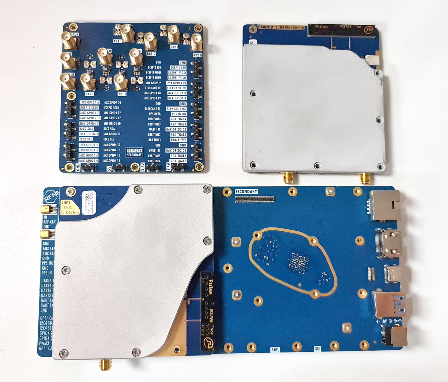
Last year the RFNM (RF Not Magic) software-defined radio was announced and opened up for pre-orders. RFNM is an SDR based on the new 12-bit LA9310 baseband processor chip, and together with either a 'Granita' or 'Lime' daughter board it is capable of tuning from 10 - 7200 MHz or 5 - 3500 MHz respectively. It is also capable of wide bandwidth - up to 153.6 MHz on a host device like a PC. The RFNM is affordable, costing US$299 for the motherboard, US$179 for the Lime board, and US$249 for the Granita board. Currently, the second production batch is available for preorder.
Recently we received our RFNM order, with both Granita and Lime boards. This is a review of our initial impressions and tests on it. Note that while the RFNM is capable of transmitting, in this review we did not test that capability.
Physical Review
The RFNM motherboard comes as a PCB with a large heatsink on the bottom and a very quiet inline fan. The daughterboards connect to the motherboard with a board-to-board connector and are secured in place via seven screws. There is another board-to-board connector for a second daughterboard to be connected, but in this review we did not test it.
On the right side there is a 4-18V DC barrel power jack and USB-A, USB-C, HDMI and Ethernet connectors. There is also a SIM card and SD card slot on the side. On the left of the board are MMCX connectors for external reference clock, and clock out. There are also various header pinouts for PPS OUT/IN, UART, I2C, GPIO and PWM. On the heatsink side there is a JTAG connector, jumpers for resetting the firmware, and pads to solder on an OCXO.
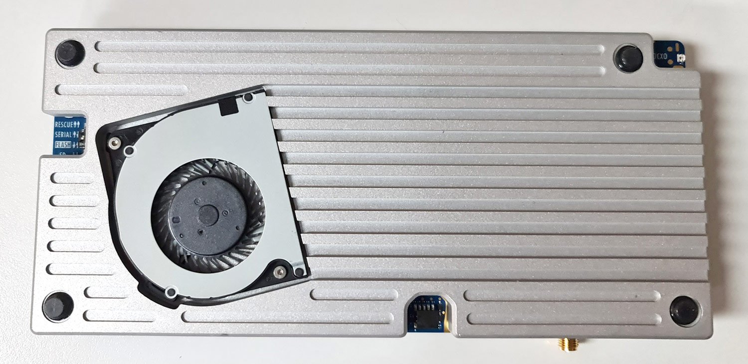
RFNM Motherboard and DaughterboardsRFNM bottom with heatsink, fan and rubber feet.
The device feels solid but there are a few exposed SMT components on the rear that have the potential to be knocked off with rough handling. All the main connectors are through-hole soldered and will not break off easily. During operation, the heatsink stays warm to the touch, and does not get too hot. The fan blades are exposed but should be safe from fingers and debris being on the bottom.
Initial Firmware Download
The device requires power from a 4 - 18V DC barrel jack and connects to a PC via a USB-C or USB-A port. According to the developer, it requires a 10-15W capable supply. In the tests below we used a 9V 2000mA switch mode supply, and a 12V 3000mA capable linear supply.
The device comes shipped without firmware, and the first setup step involves plugging in an internet-connected ethernet cable to automatically download and install the latest firmware. If you don't have an internet connected ethernet cable, an alternative is to plug in a USB stick with the latest firmware installed on it. The firmware installation took only a couple of minutes and went smoothly.
Initial Tests with SDR++
The easiest way to get something working with the RFNM is to use the custom SDR++ build included on the RFNM itself. When you plug in the RFNM it shows up on your PC as a disk drive, with an SDR++ folder. Getting started is as easy as running that SDR++ exe and clicking Play.
Initially, we encountered an issue where the RFNM wouldn't show up in SDR++, and wouldn't show up as a disk either. However, after flipping the USB-C connector it worked. This is an issue that continued throughout, and sometimes flipping wouldn't even work, but it always connected after a few reconnection attempts, and once the board was connected it was stable.
Lime Daughterboard Tests
We first tested the RFNM with the Lime daughter board. This is a board based on the Lime LMS7002 chip which is the same chip used in the LimeSDR. Here only the IQ output of the Lime chip is used, not the ADCs.
At this point, it's important to note that software support for the RFNM is still in the very early stages and SDR++ currently has no gain controls implemented. SDR++ is third-party software to RFNM so it's not any fault of the RFNM team. (NOTE: In the last few days after having already written this review, there have been several commits to SDR++ regarding RFNM, so this may already be resolved)
However, it is possible to SSH into the Linux OS system running on the RFNM system and change the gain setting through a bash command. To connect to SSH a network-connected ethernet cable needs to be connected to the board (alternatively you can use the UART port on the side of the board with an adapter). Once logged in via SSH we can browse to "/sys/kernel/rfnm_primary/rx0" and edit the value in the 'gain' text file. Then to activate the changes, simply set the value in the 'apply' text file to 1. This allowed us to optimize the gain settings for best reception.
cd /sys/kernel/rfnm_primary/rx0
echo 30 > gain && echo 1 > apply
RFNM with Lime daughterboard on the WiFi bandsRFNM with Lime daughterboard receiving mobile basestation signals.
With the ability to set the gain, the Lime board works great. Signals are strong in the VHF and UHF bands where sensitivity is approximately -135 dBm, and there is little sign of imaging with appropriate gain settings. In the 2.4 GHz band, the sensitivity remains good at around -130 dBm too. Although the advertised max frequency range is 3500 MHz, we were able to receive up to about 3.85 GHz with reduced sensitivity.
On HF, however, the Lime board performs very poorly. We start to see a drop off at around 50 MHz where the sensitivity is roughly -93 dBm, at 30 MHz about -58 dBm, and 15 MHz about -37 dBm.
Granita Daughterboard Tests
In the second test, we removed the Lime board from the RFNM motherboard and installed the Granita daughterboard. The Granita daughterboard is based on an Arctic Semiconductor 'Granita' chip, an RFFC2071A mixer, and several preselectors.
Unfortunately, we are very disappointed in the performance of Granita as there is very significant imaging of signals, and this wipes out the ability to cleanly receive almost every band. According to Davide, this problem is a firmware issue with the Arctic Semiconductor Granita chip that can maybe be fixed in the future, but there is no guarantee that it is fixable, as any fix is at the mercy of the Arctic Semiconductor, who don't seem to be very responsive to the issue. Davide (creator of the RFNM) writes:
In the Lime board, the IQ LPF works properly. For granita, it doesn’t work at all, like the -3 dB point of the 20 MHz LPF option is 100 MHz+. The manufacturer of the RFIC kept saying that this is a firmware bug, so I gave them a devkit to replicate, but they never fixed it over the last month. I don’t know at this point if this is a software problem or if they discovered it’s something more.
We confirmed that adjusting the gain settings on Granita did not help with the imaging problem either.
Heavy imaging was experienced with Granita (compare this to the true WiFi spectrum shown previously with the Lime board).
We also noticed that Granita was picking up or internally generating significant noise spikes. We initially assumed this was from the 9V SMPS, but even with a 12V linear power supply similar spikes were seen. The same noise was not visible with the Lime board.
Granita unknown noise spikes
Sensitivity in the bands above 600 MHz was good, at around -135 dBm. Below 600 MHz where the mixer is used, sensitivity was a bit poorer at around -123 dBm. The highest frequency we could receive was around 5900, but after about 5 GHz signals started to become very weak. The Granita board is advertised as receiving 10 - 6300 MHz, however, the documentation notes that the current batch is only capable of tuning to around 5 GHz. They note that the next batch should reach 6.3 GHz.
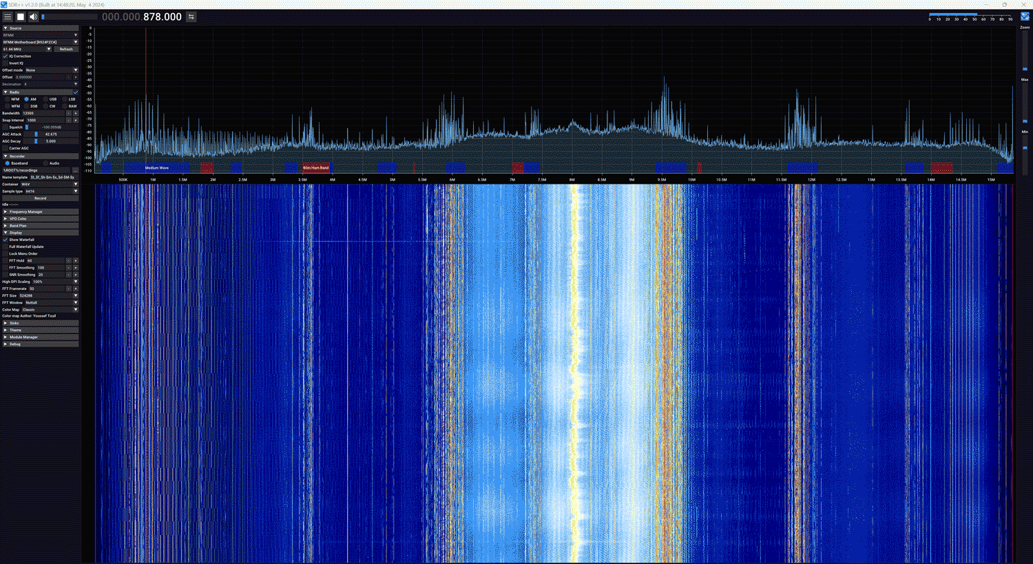
The Granita board was able to receive broadcast AM, shortwave, and ham frequencies with good signal strength. At 15 - 50 MHz the sensitivity is roughly -115 dBm.
Granita receiving the 0 - 15 MHz.
At the time of this review, we cannot recommend that anyone purchase the Granita board unless they are working in a very controlled environment. We hope that in the near future the IQ LPF problem can be fixed to make the Granita board usable.
GNU Radio Tests (Windows)
The file drive on the RFNM also comes with a Soapy driver available. We copied the RFNMSupport.dll file from the RFNM drive over to our GNU Radio radioconda installation's SoapySDR folder at C:\Users\proje\radioconda\Library\lib\SoapySDR\modules0.8. Then we opened GNU Radio and opened the gnuradio_example.grc file. This brings up a FFT and waterfall display like in SDR++ and with the Gain controls exposed. With the gain controls exposed the Lime + RFNM combination works great.
The daughterboards also have built-in antennas that can be switched in or out using a drop down box in the GNU Radio UI. The built-in antenna on both boards is a Pulse W3796 which has an advertised range of 698 MHz to 2.7 GHz. While the built-in antenna works well for nearby bench reception, we preferred to still use our outdoor dipole antenna for better reception.
153.6 MHz Bandwidth Mode
It's possible to set the RFNM to provide even more bandwidth by connecting two USB cables to the PC. That gives us up to 153.6 MHz of 12-bit data. Enabling this mode requires editing a variable via the terminal
Once this was set we were able to edit the samp_rate block in the GNU Radio example, and set it to 153.6 MHz. At the moment the current SDR++ does not support the 153.6 MHz sample rate.
RFNM Running 153.6MHz in GNU Radio.
Conclusion
It's clear that the RFNM is cutting edge, yet affordable, and has great potential and excellent features and specifications. The built-in processor, DSP and GPU capabilities on the RFNM could be game changers in the near future. However, at the time of this review, the software support is still in its very early stages, documentation is lacking, and it's not yet recommended for mainstream users who just want to plug in and get started with an SDR for listening and decoding signals.
Regarding the Granita daughterboard, we would probably hold off on purchasing this until there is some clarification on the IQ LPF fix.
If you are an advanced SDR user who is comfortable with GNU Radio, Linux and advanced applications like setting up and running mobile basestations, then the RFNM may be a good choice. We are looking forward to applications that make use of the onboard DSP and GPU capabilities.
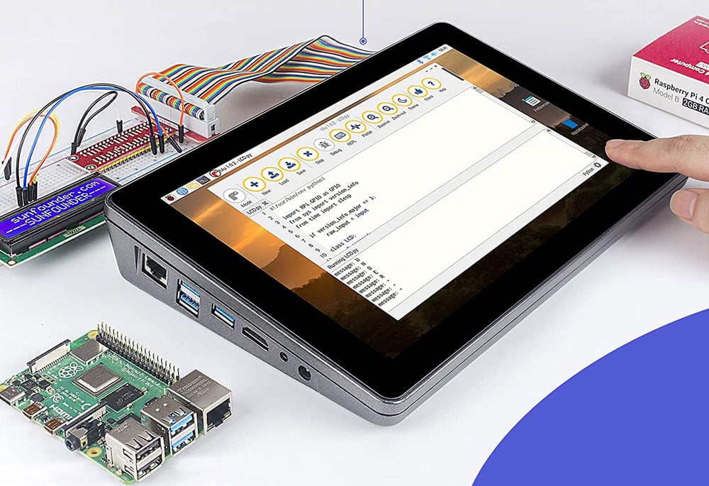
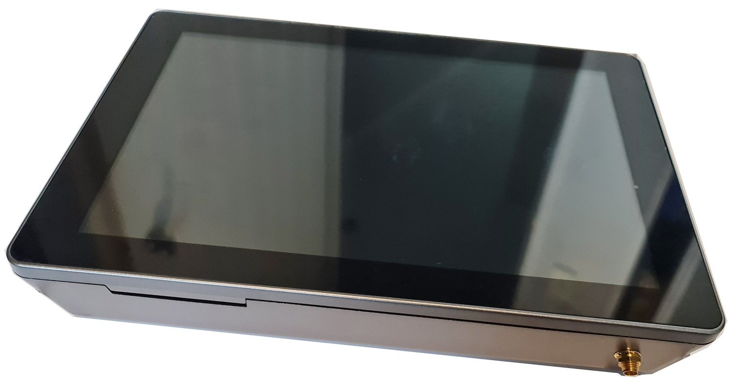
The Raspad 3.0 is a portable tablet enclosure for the Raspberry Pi 4B. It comes with a high resolution 1280 x 800 10.1 inch touch LCD screen, built in speakers, built in battery and a plastic enclosure that houses the LCD driver board and Raspberry Pi. Accessible on the side of the enclosure are the USB, HDMI, ethernet and audio ports which connect via the LCD driver board. They also include an accelerometer shim which allows the screen to autorotate.
A few months ago SunFounder, the company behind the RasPad 3.0 reached out to us and asked if we wanted to review the product with a free sample. Normally we don't review products unrelated to SDR like this, but given the amount of RTL-SDR software available for the Raspberry Pi, and what appeared to be sufficient internal space, we were curious if there was a way to turn this into a portable RTL-SDR tablet...
The RasPad 3.0
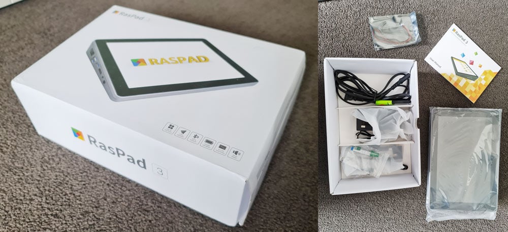
Unboxing
A few weeks ago the Raspad 3.0 arrived, well packed and with all the advertised components. Note that the Raspad 3.0 does not come with a Raspberry Pi 4B, this is something you will need to provide on your own.
Inside was a mains power cable, 15V DC power brick, two HDMI jumpers, a USB jumper, accelerometer shim, SD card ribbon, small 5V fan, heatsinks for the Pi, screwdriver and mounting screws, a manual and the RasPad LCD screen itself.
The Raspad 3.0 Box and Unboxing
Assembly
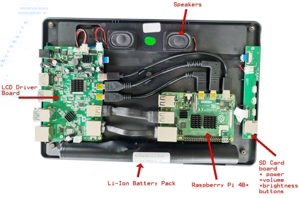
Assembly is straight forward. You unscrew the enclosure using the provided screw driver, insert the Pi 4B, screw it down, connect all the cables from the Pi to the LCD driver board and SD card slot, then reassemble. After inserting the Raspberry Pi 4B and attaching all the cables this is what the inside looks like.
Inside an assembled RasPad 3.0
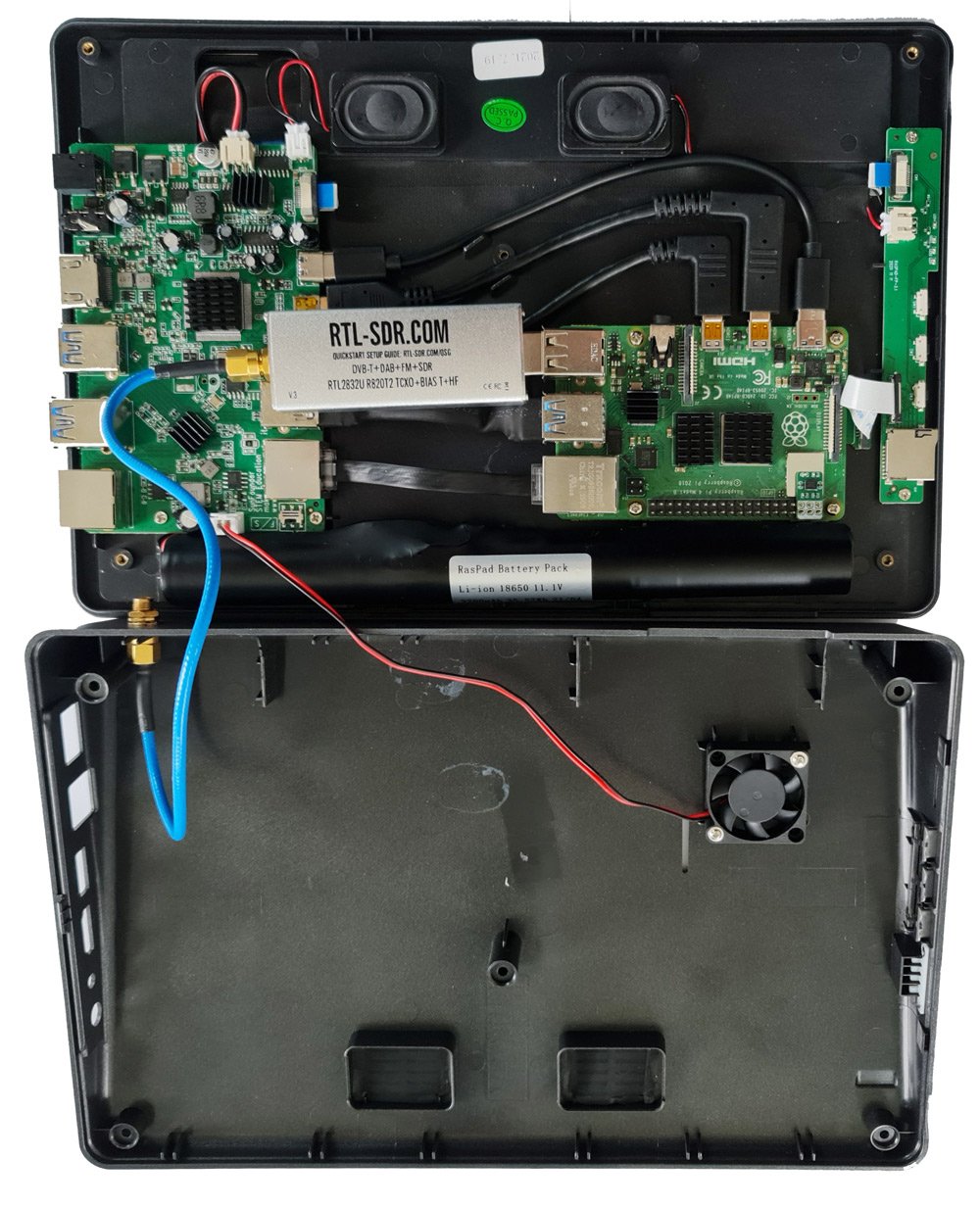
Now we could have reassembled the enclosure here, but we wanted this to be a portable RTL-SDR tablet, with the RTL-SDR and an SMA antenna port built in.
It turns out that the best way to fit in an RTL-SDR Blog V3 is to directly connect it to the spare USB port on the Pi. You might also consider using a micro style RTL-SDR which would fit more easily, but those do tend to get quite hot in a small package, and can be quite bad with internal noise. Also good shielding is probably quite critical in this application due to the dongles proximity with the LCD driver board which could be an RFI source.
The SMA side of the RTL-SDR Blog V3 rests nicely on top of the USB port of the LCD driver board providing some stability, and when the bottom lid is assembled there is plenty of clearance and no squashing.
Next we drilled a hole on the rear wall of the bottom half of the enclosure for the SMA female port, and tightened the SMA connector down with a nut. In the future we'll be upgrading this to a long barrel style SMA female connector, as a regular SMA female connector is a bit short. Then a short well shielded SS405 coax cable was used to connect to the RTL-SDR dongle.
RasPad 3.0 with RTL-SDR Blog V3 InsideRaspad 3.0 with SMA port hacked in
ProTip: Do take care to remember to remove the SD card when disassembling the RasPad! If you don't you'll end up with the SDcard slot getting ripped from it's ground traces. This happened to us, but we were able to easily solder it back on. There is a sticker on the backside of the enclosure warning about this.
Software & Testing
SunFounder provide a custom Raspbian distribution designed specially for the RasPad. However, we decided to instead install the DragonOS Pi64 Distro which is an Ubuntu distribution for the Raspberry Pi 4B that has many built in SDR programs. We burnt the image to a SD card, inserted it on the side, plugged the Raspad in to the power connector, and held the power button down for a few seconds to turn it on. Despite a few initial error messages saying it cannot enable the USB ports, everything eventually booted just fine.
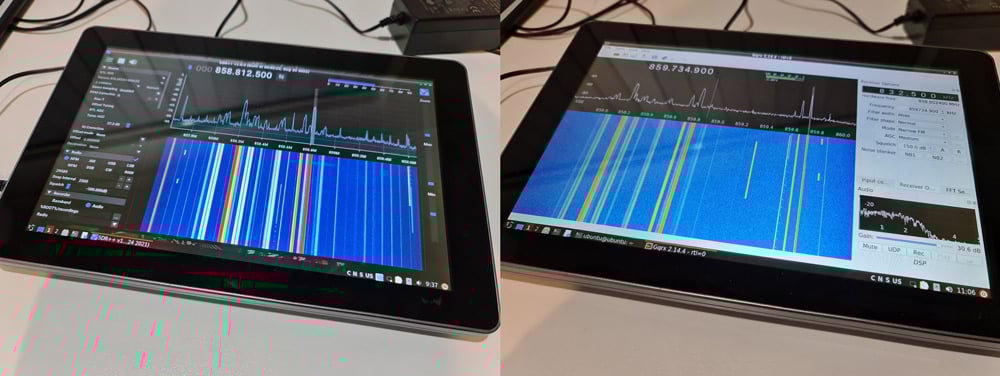
We then plugged in a cable going to one of our multipurpose dipole antennas mounted just outside the office window, and tested both SDR++ and GQRX. In both cases we were immediately able to connect to the RTL-SDR and receive signals with signal strength equivalent to that received by our desktop PC, indicating that LCD interference was not a problem.
The resolution of the screen is high enough and images and text are clear. The screen is also decently bright, and brightness can be adjusted using the buttons on the side.
RasPad 3.0 with built in RTL-SDR running SDR++ and GQRX
DragonOS Tablet Compatibility Issues & Fixes
As DragonOS is not designed for a tablet setup, there were a few bugs. It should be noted however that these issues are not a reflection on the Raspad hardware, as obviously the official Raspad OS will not have these issues as it's designed specifically for tablet use.
We initially had no sound in SDR++ from the built in speakers. After some troubleshooting we managed to get sound by disabling the headphone jack in the audio mixer settings, which appears to be the default output in DragonOS. To do this, click on the speaker icon on the bottom right task bar and click on Mixer. Then go to the Configuration tab and uncheck the second Built-in Audio entry. Close it, and open SDR++.
Disabling the headphone jack to get the built in speakers working.
In DragonOS the touch screen works fine, although it is difficult to click on small buttons. There is no onscreen keyboard available by default. We couldn't find a way to enable a tablet mode in DragonOS, so instead opted to install an onscreen keyboard called 'onboard' via 'sudo apt install onboard'. The accelerometer is also not enabled in DragonOS. We did not attempt to fix this as we have no need for screen rotation.
Interference
LCD screens are well known to be sources of RF interference, and putting an SDR in close proximity to one could result in the spectrum being very noisy. However, without an antenna connected we did not notice any interference across the spectrum from the LCD screen. It appears that the LCD RFI noise levels are not too bad, and the shielding on the RTL-SDR Blog V3 and the coax jumper cable is good enough to prevent any being received. When an antenna with a few meters of coax was connected (such as a magwhip or our portable dipole) we also didn't notice any LCD interference.
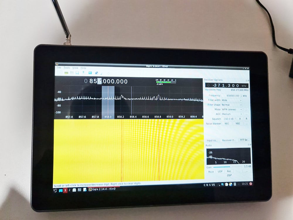
However, when a SMA telescopic antenna was connected directly to the SMA port we did start noticing the telltale spikes across the spectrum that are typically generated from LCD screens. If the magwhip or dipole was also moved within 2-3cm of the LCD screen, we also saw these interference spikes appear.
LCD Screen interference appears with a telescopic whip connected directly to the SMA port.
So it would be recommended to use a magwhip or dipole that has a coax run that can sit a few centimeters away from the screen. This limits the handheld ability of the RasPad a little, but you'd probably want a magwhip, dipole or other antenna over a directly connected telescopic whip for better reception anyway.
Battery Life
We tested a worst case scenario, with the RasPad running the RTL-SDR and SDR++ continuously at the brightest screen setting. With this test the battery lasted 2 hours and 10 minutes from a full charge. Presumably if the screen was dimmed and turned off for some periods of time, it would easily last 3-4 hours.
Portability
The total weight of the Raspad including our mods is just under 1 kg (2.2 lbs). About double the weight of a modern tablet, but still light enough to be easily carried.
Other Notes
The small 5V fan provided in the kit is unfortunately a bit noisy, and it's cooling ability is seems limited. We've seen these small fans on other Raspberry Pi cooling accessories and found that they are next to useless at cooling. It would be good to see a slightly larger and quieter fan, or perhaps a better passive cooling heatsink.
The power brick output is 15V, 2A. Ideally we would be able to charge the RasPad via a car/boat 12V connection as well. We're awaiting a response to see if this is possible. Update: Unfortunately 12V seems to be a no-go, quoting SunFounder "the 12v supply may cause the Raspad to fail to charge, as the minimum is 15v".
Conclusion
The RasPad 3.0 in our opinion overall a good product. It allows you to easily go portable with your Raspberry Pi 4. While it was designed for other projects, there was just enough hackability left in it for us to fit a RTL-SDR Blog V3 and antenna port into the enclosure, yielding us a clean and portable SDR solution.
With at least 2 hours of battery life when running an RTL-SDR and software, we can easily see this being taken out in the field for spectrum analysis, decoding with rtl_433, or for portable listening to the airband, trunking etc. However, some customization of DragonOS or the RaspadOS is going to be needed to get the most out of the touchscreen.
There are also alternative LCD screen products designed for the Raspberry Pi where you sit the Raspberry Pi on the back of the screen. But it's unclear if there would be enough space inside to fit an RTL-SDR, and not to mention the lack of a battery. We also previously reviewed the Elecrow CrowPi which is somewhat similar, but a lot more clunky if you're just after a pick up and go portable SDR tablet solution. There are also higher end higher priced laptop style enclosure products for the Pi, like the Pi-Top but we're unsure if they're likely to fit the RTL-SDR internally this easily.
Disclaimer: We do not receive any compensation for this review apart from a free Raspad 3.0.
We also recently came across this review from German YouTuber Manuel Lausmann who installed and ran SDR++ on the Raspad with an SDRplay RSP SDR.
The Airspy team have recently been working on a preselector retrofit product for their HF+. The Airspy HF+ already has excellent dynamic range and sensitivity, but by adding a preselector they seek to improve performance enough to claim that the HF+ is as good as or even better than much more pricey SDRs like the Perseus by achieving dynamic range figures of more than 105 dBm.
A preselector is a filter or bank of filters that attenuates out of band signals. This is useful as radios can desensitize if an unwanted signal comes in too strongly. For example, if you are tuned to the 20m band, but there is a very strong MW signal, the SNR of your desired 20m band signal might be reduced. Radios with a natural high dynamic range design like the Airspy HF+ are less affected by this problem, but for the strongest of signals use of a preselector can still help.
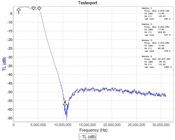
The Airspy HF+ preselector needs to be soldered directly onto the HF+'s PCB, and once installed it automatically switches bands using GPIO expansion ports controlled automatically via tuning in SDR#, so no external switching is required.
The expected pricing of the HF+ preselector is US$49, and it will be ready for sale in a few weeks.
Measurements
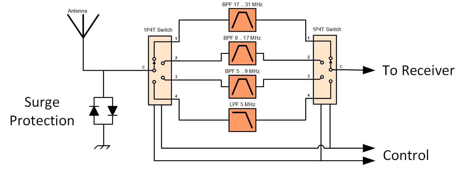
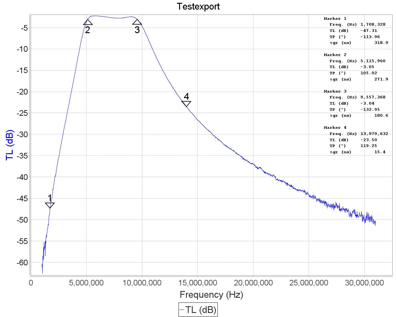
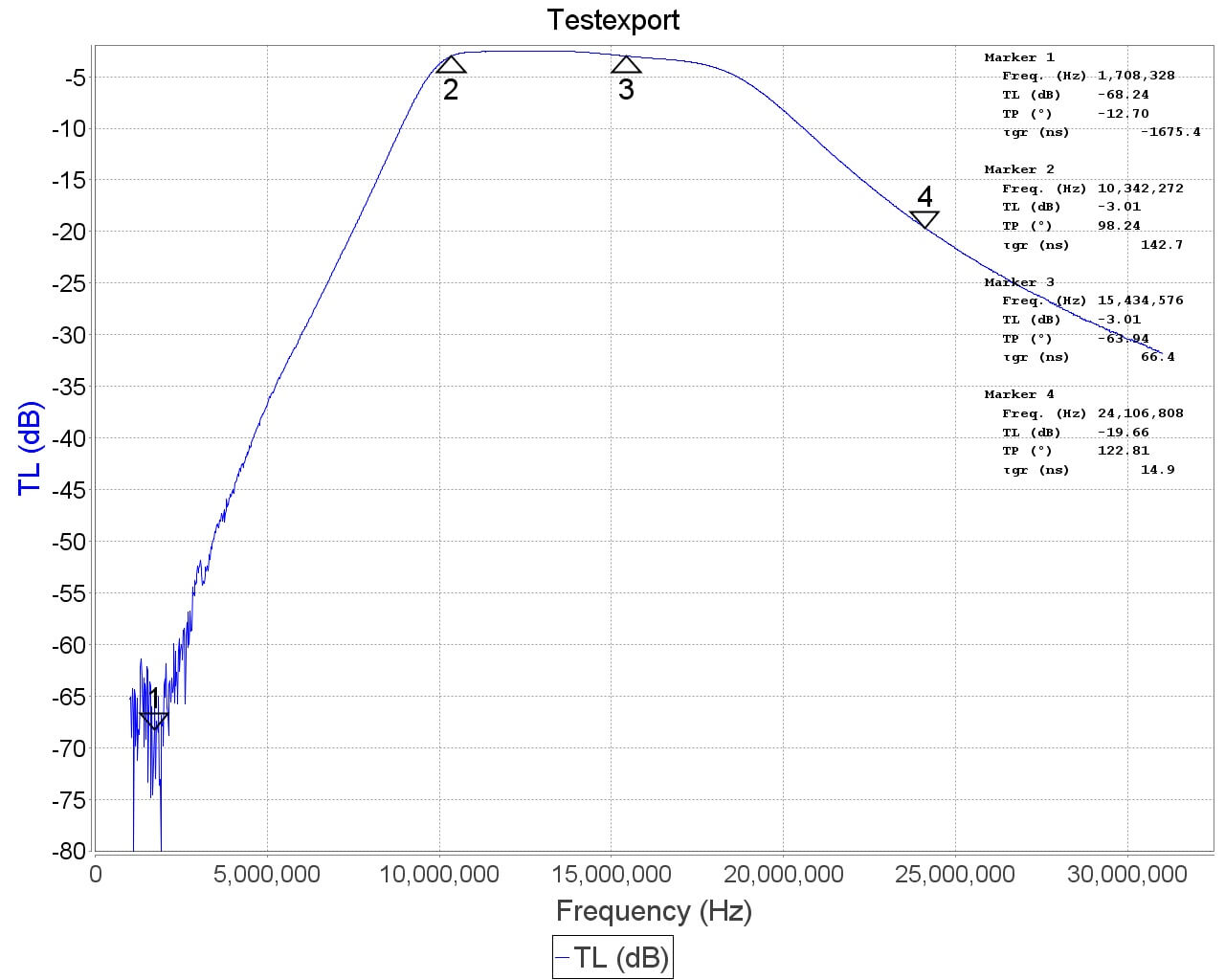
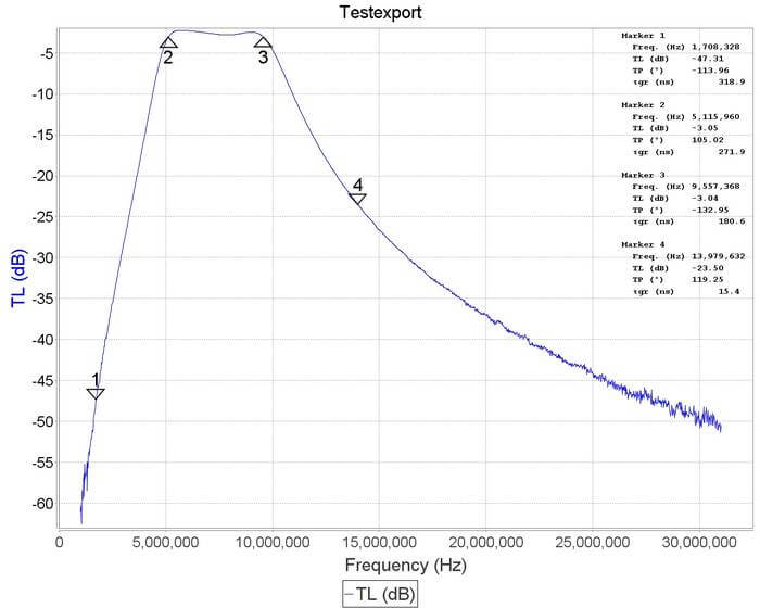
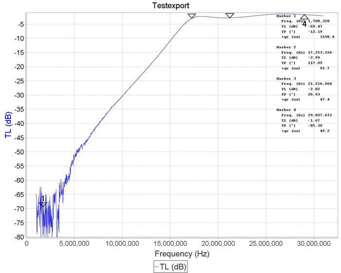
We received a prototype of the filter a few days ago and have been testing it out. From measurements on a VNA, we found that the preselector features four bands of operation:
0 - 5.2 MHz
5.2 - 10 MHz
10 - 17 MHz
17 - 30 MHz
Airspy have also provided us with a block diagram schematic which we show below.
HF+ Preselector Schematic
Insertion loss appears to be mostly below 3 dB with fairly steep skirts especially on the lower side. The top three filters do an excellent job at blocking out the broadcast AM band. Below are some VNA plots that show the filter responses.
Installation
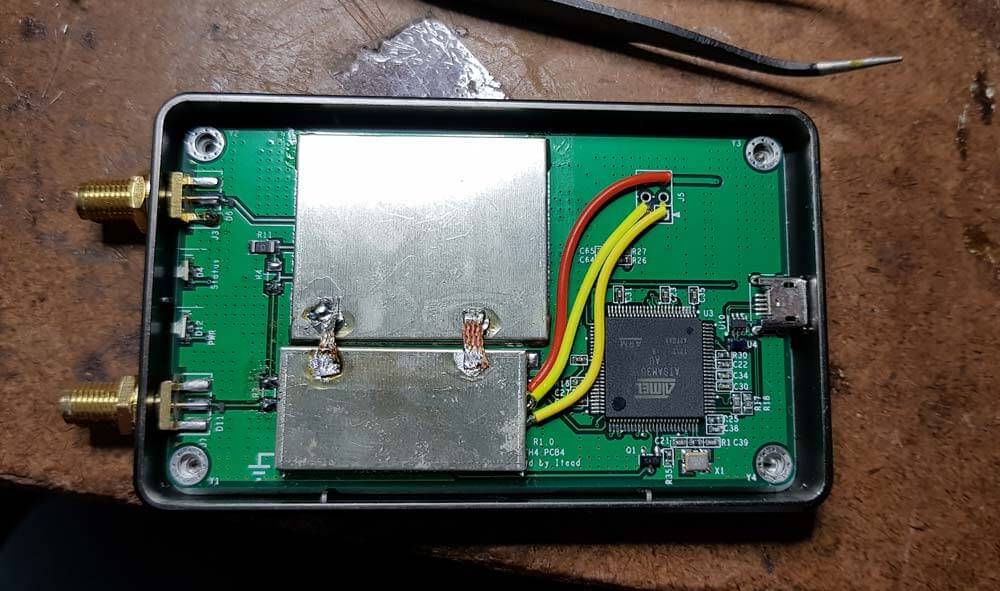
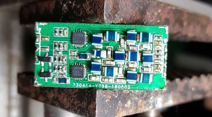
The preselector comes in a small 3.2 x 1.7 cm sized PCB that is fully covered with a metal shielding can. To install it you need to carefully solder it onto the HF+ PCB. This can be a little tricky since the pads are so small, but if you're experienced with soldering it shouldn't be an issue.
First you need to open the HF+ and remove R3 from the HF+ PCB, which is a zero ohm resistor.
The preselector PCB can then be positioned and the two IN and OUT pads soldered in place.
Then you'll also need to connect the power and 2x GPIO lines to the preselector using wires.
Now you need to bridge the two shielding CANs with a thick bit of wire. We simply used two cuts of copper solder braid to do this.
Finally is also recommended to update the HF+ firmware to the latest version and download the latest version of SDR#.
Once soldered in place the preselector is ready to use, and the HF+ cover can be put back on. It is expected that the commercially sold versions of the preselector will come with detailed installation instructions.
In the first photo below we removed the shield to see what was inside, and the second photo shows it installed on the HF+ PCB.
Using it on a RTL-SDR V3
Whilst the preselector is designed for the Airspy HF+, there's no reason why it couldn't also be retrofitted onto other SDRs, such as our RTL-SDR V3, for use in improving direct sampling mode performance.
The V3 has spare GPIO ports that can be used to control the filter, and 5V for powering the filter could be tapped off the PCB as well. Currently we're considering making a breakout PCB for the filter than might aide with this.
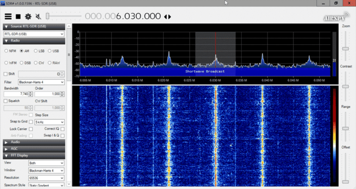
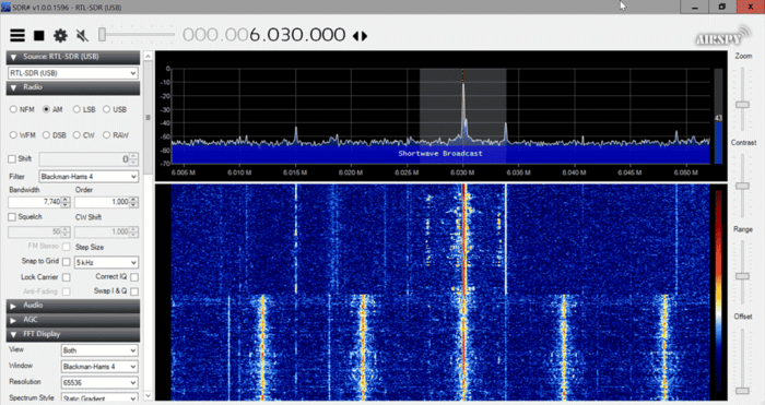
We did a quick test with the preselector connected to the RTL-SDR V3 running in direct sampling mode, and as expected performance is much better, especially above 5 MHz once the second filter kicks in. This is because the second, third and fourth filters all heavily attenuate the MW broadcast AM band, which is the main source of overload issues on HF.
The following screenshots show how much the filter was able to reduce the signal strength of AM broadcast when the second 5.2 - 10 MHz filter was turned on. This reduction was enough to prevent overload on all the higher bands.
HF+ Results
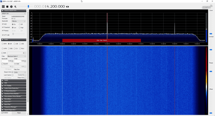
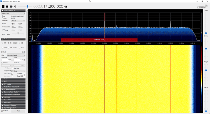
For the HF+ we tested by injecting a strong signal into two HF+ SDRs, one with the filter installed and the other without. The HF+ with the filter was routinely able to withstand much higher signal powers without any signs of overload occurring, and no degradation due to insertion loss was observed.
The screenshots below show an experiment with a weak desired signal injected at 14.2 MHz, and a strong unwanted signal being injected at 1.5 MHz. With the unwanted signal at 5 dBm, the filtered HF+ showed no signs of overload, whilst the unfiltered HF+ had the AGC kick in to increase the front end attenuation, reducing the signal strength by about 20 dB and raising the noise floor.
Other Reviews
Other reviewers have also received the preselector and have been testing it. Fenu radio has uploaded a short review, and plans to write more in the future. He's also made his HF+ with preselector available for public use via SpyServer (details in his post). In the video below Leif SM5BSZ reviews the preselector and runs through several tests while comparing it against the Perseus. His results seem to show that the Persues gets a +25 dBm IP3, whilst the HF+ with the latest firmware and preselector is able to obtain a respectable +10 dBm IP3.
hfpluspresel2
Conclusion
For most people, the dynamic range of the HF+ is probably already more than enough, but if you are receiving very strong signals, the preselector can help get you get more performance out of the HF+. Of course the preselector cannot help if you have strong signals within the filter bands.
If you're looking to get the most out of your HF+ then the filter at only $49 is a pretty good deal. Just take note that you'll need to open the HF+ and be comfortable with soldering onto the PCB.
Recently, SunFounder sent us a free review unit of their latest "Pironman 5 MAX" enclosure for Raspberry Pi 5 devices. While not directly related to SDR, we thought we'd accept the unit and review this product, as RTL-SDRs are often used together with Raspberry Pi 5 single-board computers. Depending on the number of SDRs connected and the software used, SDR applications can consume a significant amount of CPU, causing heat and throttling down of CPU speeds; therefore, adequate cooling may be necessary.
The Pironman 5 costs US$94.99 if purchased directly from the SunFounder website, and they advertise that US duties and EU VAT are included in the pricing. There is also the slightly lower Pironman 5 model available for US$79.99. The main difference between the 5 and 5 MAX is that there is only one SSD expansion slot vs two on the 5 MAX, and no tap-to-wake OLED functionality.
Overview
The Pironman 5 is what we would consider a high-end enclosure for the Raspberry Pi. It includes a large CPU tower cooling heatsink with a fan, along with two case fans to keep the internal temperatures down.
It also adds a dual slot NVME M.2 expansion board to the Pi 5, so that you can install two SSDs or one SSD and a Hailo AI accelerator module. SSDs might be useful for RTL-SDR users who are recording large amounts of IQ data, or saving many weather satellite images, for example. The Hailo AI accelerator module could turn a Raspberry Pi and RTL-SDR into an RF intelligence powerhouse. One advanced AI use-case might involve running local Whisper speech recognition to log voice communications to text, followed by using a local LLM to summarize daily received data (noting that you'll need to wait for the Hailo-10H model to run local LLMs).
Finally, it also adds an OLED status display, which shows current CPU temperature and fan speeds, as well as an on off button.
Another plus is that the GPIO header remains accessible on the outside of the enclosure, thanks to an extender included in the design.
Pironman 5 Fully Assembled
Assembly
Assembly of the Pironman 5 took just over 30 minutes. It involves screwing in standoffs, seating the heatsink/fans, connecting jumpers and ribbon cables, and screwing down the panels. A nice color paper assembly manual is provided, making the installation easy to follow. Anyone who is mildly familiar with installing connectorized PC components should have no trouble.
All parts included with the Pironman 5.Pironman 5 Assembly ManualPironman 5 Built (Acrylic side panels off)
Software Installation and Usage
After assembly, you can simply insert a freshly burned Raspbian image into the SD card slot and power on the unit.
At this stage, you now need to install some software to properly control the OLED, CPU fans, and case fans. This involves installing some software from their GitHub, but you can simply copy and paste the commands in the terminal one by one.
Once the software is installed a web UI is exposed at <IP_ADDR>:34001. Here you can monitor various stats including CPU temps, and make changes to the OLED, RGB and fan behaviour.
Pironman 5 Web UI
OLED QC Problems?
Unfortunately, our unit had a problem where the OLED screen wouldn't work. We attempted fresh software installs and reseated all cables and connectors, but had no luck. Upon contacting SunFounder, they immediately sent us a new OLED screen to try. But the replacement also did not work.
However, when trying the new screen, we noticed that the screen would briefly light up when we pressed on the FPC connector. Upon inspecting the FPC connector, we noticed that some pins on the PCB looked suspiciously low on solder compared to the others, so we applied flux and used a hot soldering iron to refresh them. After doing this, the OLED screen began working again.
Based on our dealings with SunFounder, we believe that they're support is good, and any customer facing similar issues would be supplied with replacement parts if required.
Pironman OLED Screen Working
Usage and Performance with RTL-SDR
As expected, with the great cooling in place, the Raspberry Pi 5 never throttled down when running an RTL-SDR with SDR++. We also tested it with our KrakenSDR system, which requires more CPU, and found great performance too.
The rear GPIO fans are quiet enough, and the CPU fan makes almost no noise inside the enclosure. We ran a stress test using the 'stress' Linux package, which can push all four CPU cores to 100%. With the fans running in a room with an ambient temperature of 22 degrees, we saw that the CPU temperature never went above 55 degrees C.
While still running 'stress', we manually disabled the two GPIO fans, and the temperature stabilized at around 66 degrees C. So the rear fans may only be required to be on when you have an SSD or AI module installed.
Conclusion
If you're looking for a high-quality enclosure and cooling solution for the Raspberry Pi 5, the Pironman 5 MAX is probably the best high-end solution available. Not only does the enclosure protect the Raspberry Pi 5 completely, but the cooling performance is excellent, and the ability to add SSDs and AI modules is great too.
Disclaimer: We were given a unit for free in exchange for an honest review. We received no other compensation.
As mentioned in a previous post last week, UUGear have recently released their VU GPSDR expansion board for their Vivid Unit single board computer with touchscreen. Together, this combination results in a handheld Linux system, with built-in RTL-SDR and upconverter.
The VU GPSDR has some interesting features, including:
GPS-assisted 24 MHz clock for improved frequency accuracy and stability
An integrated 108 MHz up-converter for HF (under 30 MHz) reception
Dual programmable rotary encoders for tactile control
A software-controlled frequency output port for experiments
Software features, including OpenStreetMap integration and ADS-B aircraft tracking
Vivid Unit with VU Extender and VU GPSDR
Assembly
We won't repeat the assembly steps as the instructions show everything clearly, but we can say that the assembly steps were clear, and the assembly itself was easy. It was simply a case of plugging in a few jumper wires between the Vivid Unit and VU Extender board, screwing down the extender board, and then slotting in the VU GPSDR into the Extender boards mini-PCIe slot, before finally screwing down the GPSDR. Assembly took less than 10 minutes.
Physical Design Review
The system is put together like a sandwich. You have the screen and Vivid Unit on the top, then the Extender board, and finally the VU GPSDR on the bottom.
The Vivid Unit and GPSDR are essentially bare PCBs that connect to one another via the PCIe slot on the Vivid Extender board. This means that there is no enclosure, and you are essentially handling PCB parts in their raw form. In the future, we would like to see an optional enclosure to protect the unit better.
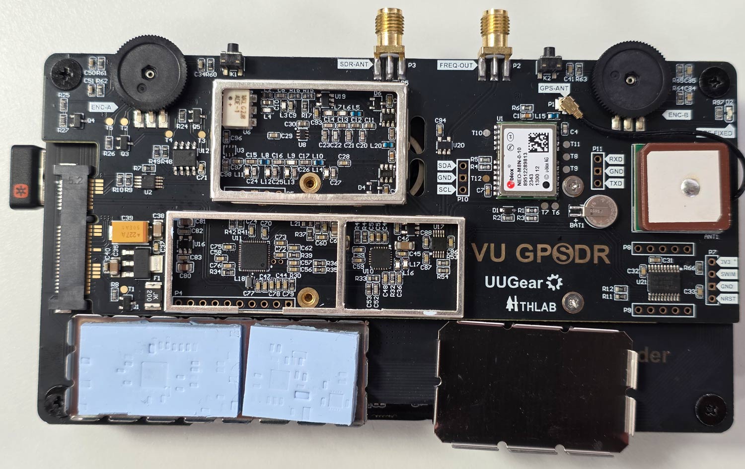
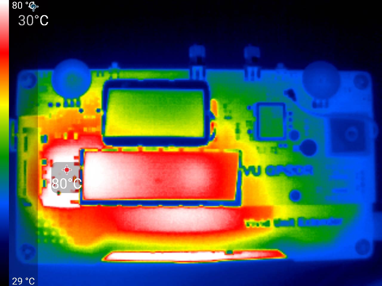
The exposed design results in some flaws that we have to point out. The shielding cans on the VU GPSSDR unit sit on the rear of the system, and during operation, they get very hot to the touch. So much so that handling the unit requires a bit of care to avoid the hot spots. Most of the heat appears to be coming from the AMS1117 LDO on the rear, which gets up to 80 °C, so be careful not to touch it accidentally. From the photos you can see that the RTL2832U and R860 are heatsunk to the shield. This is a good idea to keep the chips cool, but it also means that the metal gets quite hot to the touch. So handling the unit only from the edges is recommended.
Vivid Unit with the shielding cans removed.VU GPSDR Thermals
Secondly, because the Vivid Unit does not have a built-in battery, you need to power it separately via its USB-C port on the side. This makes the ergonomics of handling the unit a little trickier as you also have a cable sticking out. UUGear has noted that they are working on an 18650 battery pack, so this issue may be resolved in the future.
Finally, the "GPS" in the GPSDR comes from the fact that there is a GPSDO with a built-in GPS patch antenna on board. When active, a GPSDO provides excellent frequency stability, meaning that signals will be on frequency and will not drift.
But because of how the system is designed, the GPS patch antenna faces the ground when you look at the screen, even though it should face upward to get a clear view of the sky for satellite signals. However, despite this, we were happy to see that even while upside down, the patch antenna was able to receive several GNSS satellites with sufficient strength in order to obtain a fix when used outdoors.
Indoors, of course, no GPS fix is possible. But the uBlox NEO-M8N GPS module used in the GPSDR also has a fallback TCXO, so even without any GPS fix, the frequency accuracy of the system is good. UUGear also noted that the GPSDO automatically activates once a GPS fix is achieved, so no action is needed when you take the unit outdoors.
Realistically, the design issue with the GPS patch doesn't really matter anyway. For most use cases in handheld operation, the built-in TCXO will be sufficient. Any use case requiring extreme GPSDO precision will probably involve the device being mounted upside down and used remotely.
The screen is clear and bright, the two encoder wheels are non-indented and are in a good spot, and so is the SMA antenna port, although the VU Extender's USB-C plug can block the antenna SMA port if a really fat plug is used (normal-sized USB-C plugs fit OK). The screen is large and has a high resolution, making it possible to use the onscreen keyboard. However, it is still a little fiddly for typing and clicking, so we ended up plugging in a small wireless keyboard.
HydraSDR is a soon to be released software-defined radio based on the same design as the popular Airspy R2 SDR. However, compared to Airspy, HydraSDR claims to have "Enhanced PCB layout and RF front end with superior power/noise filtering, improved temperature dissipation and peak temperature management," as well as various other improvements. HydraSDR also has the distinction of being made in the USA, whereas Airspy is made in China.
Recently, Benjamin Vernoux, creator of HydraSDR and former collaborator on the Airspy R2 project, sent us a review unit of the HydraSDR. This post is a review of the HydraSDR. However, because the HydraSDR is based on the Airspy R2 and competes directly with it, the two units will be heavily compared.
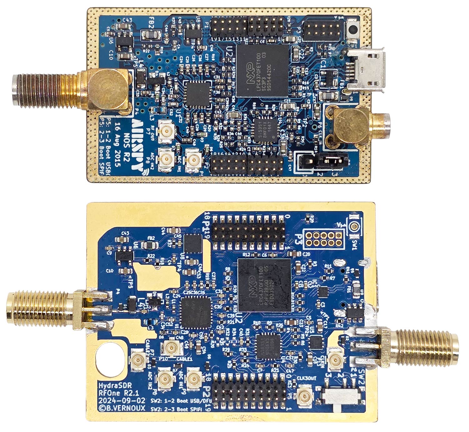
The design of the HydraSDR is very similar to the Airspy R2, which is already known to be a high-performing SDR. Both are based on the LPC4370 microcontroller and its built-in ADC, and they both use similar firmware. The circuit layout, from the top and bottom views, is also almost identical. Benjamin notes that the internal layout has been improved and that several components, such as LDOs, have been upgraded to better ones with reduced noise.
One larger change is that HydraSDR uses a Rafael R828D tuner, instead of the Rafael R860T tuner that the Airspy uses. Both tuners are very similar in terms of operation and performance as they are based on the same design and technology. The R828D has two additional RF input pins; however, on the HydraSDR, they are unused but are routed to two uFL connectors on the bottom of the PCB for advanced users.
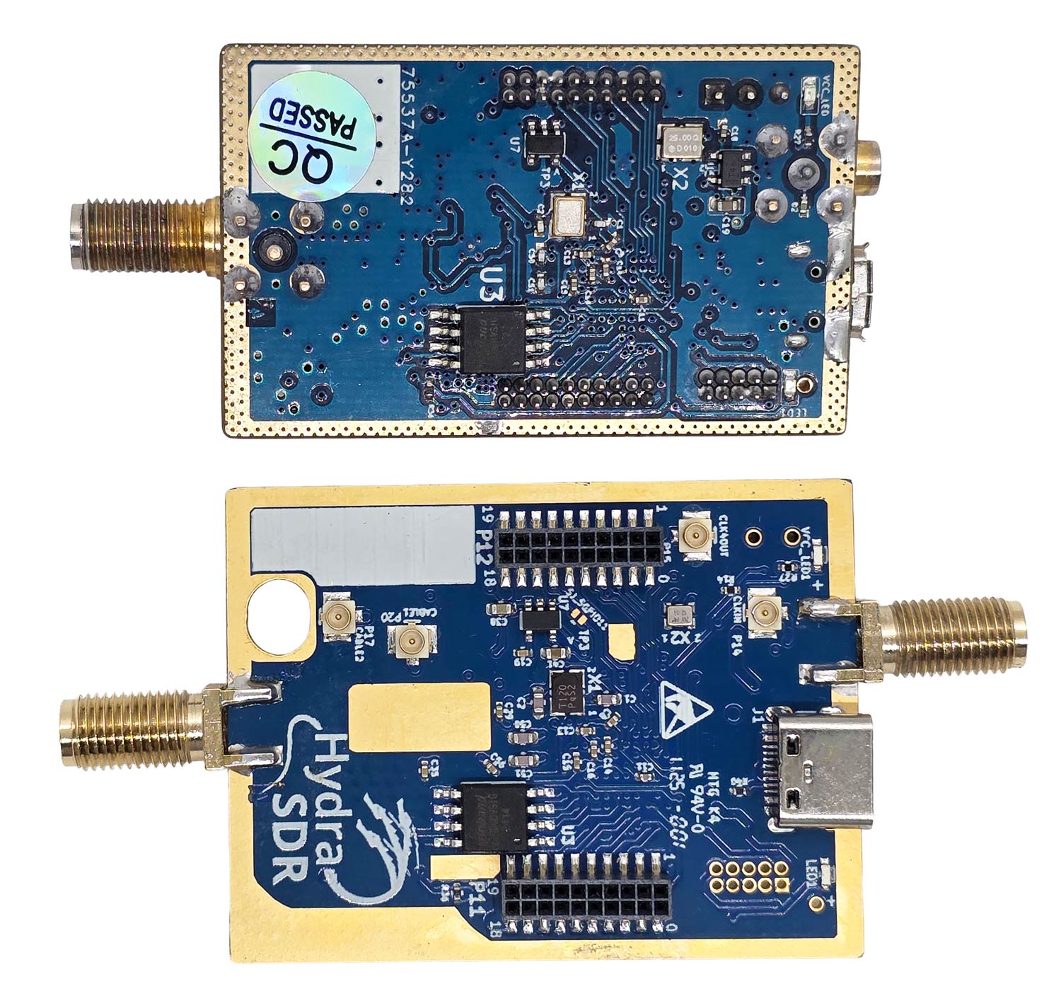
Airspy (Top) and HydraSDR (Bottom) PCB Top SideAirspy (Top) and HydraSDR (Bottom) PCB Bottom Side
Both the HydraSDR and Airspy come in a black anodized aluminum extruded enclosure. The Airspy's enclosure is more compact, but the HydraSDR enclosure is purposely oversized to accommodate up to three HydraSDR PCBs.
However, additional holes for two extra SMA ports and two extra USB-C ports have not been pre-drilled, so we assume the 3x unit may be a separate product coming out in the future. The HydraSDR also utilizes an SMA port for the optional CLK-IN port, unlike the MCX port on the Airspy.
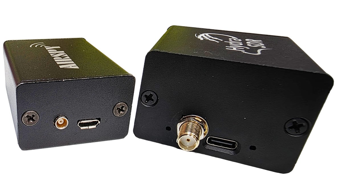
Airspy (Left) and HydraSDR (Right) Side Profile
A major win for the HydraSDR is its use of a USB-C connector, whereas the Airspy R2 still uses a micro USB connector. (We note that it is a USB-C connector, but not USB3.0, it is still USB2.0).
The microUSB connector on the Airspy R2 is less robust and can easily disconnect if bumped, even with brand-new cables. The connection on the HydraSDR is rock solid, and no amount of reasonable bumping of the cable can disconnect it.
The HydraSDR spec sheet also mentions its suitability for phase-coherent applications, such as radar. However, although you can run all three from the same clock, from what we can see, specialized firmware, software, and external signal and/or noise source hardware would still be required for sample and phase alignment, as the system can not be naturally coherent. We're unsure whether the company will be directly supporting coherent use cases or if coherence is left as an exercise for the customer.
Software
Both Airspy and HydraSDR use the same USB VID/PID identifiers, so most software should recognize them as the same device.
We decided to see if it would run in SDR#, the official software of Airspy. Upon selecting the device as an Airspy R2 in SDR#, we were able to see it work and operate just like a genuine Airspy R2. We want to note that Youssef has mentioned that, in his view, using non-Airspy products like the HydraSDR with the Airspy source would be in violation of SDR# terms, but we will use it in this review for comparison purposes.
HydraSDR Running in SDR# as an Airspy R2 Device
This is interesting because in SDR++, the software recommended by HydraSDR, selecting Airspy R2 as the device results in the device being unable to connect. Currently, SDR++ does not support HydraSDR in its latest releases; however, support is being developed.
For now, until SDR++ officially supports HydraSDR, Benjamin has released a custom fork of SDR++ that will be available on the HydraSDR website.
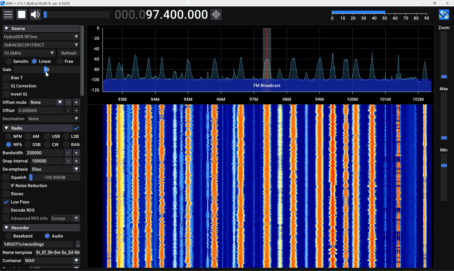
HydraSDR Running in SDR++ (HydraSDR Fork)
We note a few differences between SDR++ and SDR#. SDR# restricts the visible bandwidth of Airspy devices to 8 MHz, as this hides the edges, which contain aliased signals. SDR++ does not hide the sides. SDR# also has an 'HDR' (high dynamic range) mode for Airspy devices, whereas SDR++ does not. More on HDR mode is discussed under the testing heading.
When HDR mode was turned OFF, no differences in performance between SDR# and SDR++ were noticed.
We are also aware that HydraSDR is now supported by gr-osmosdr (GNU Radio source block), SatDump (satellite decoding software), and URH (Universal Radio Hacker).
We also found that HydraSDR runs as an Airspy in SDR-Console V3. Official Airspy software, such as SpyServer and adsb_spy, also work with HydraSDR. We suspect that most software that supports the Airspy will be compatible.
Testing
No Antenna Test
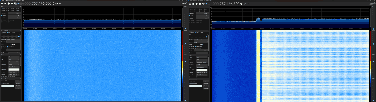
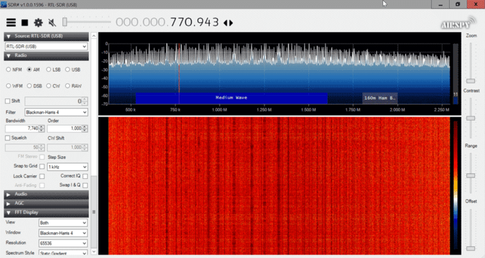
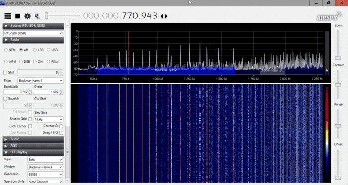
In this test, we connected each SDR to a dummy load and used SDR# to look for signals. If the SDR is shielded well, no signals should be received.
We noticed that the HydraSDR has excellent shielding and is very well protected against signals entering through paths other than the antenna. The Airspy was able to receive a strong TV channel without any antenna, indicating that it has shielding issues.
HydraSDR (Left) Airspy (Right) No Antenna Connected
Across the spectrum, the HydraSDR also has a cleaner spectrum with lower power levels on most internal spurs.
Real World SNR Tests
In this test, we received real-world signals with each SDR connected to a roof-mounted Discone, which was in turn connected to a splitter. We increased the gain settings to optimize each SDR for best SNR, which is typically just before it overloads and creates images.
We noticed that the gain distribution on the HydraSDR was slightly different from that of the Airspy, as the HydraSDR would overload on a lower gain setting compared to the Airspy. When optimizing for SNR we found that a gain setting 1-3 notches higher on the Airspy was required.
Once optimized, we found that results were very similar, with a slight 0.5 - 1 dB sensitivity edge going to the HydraSDR; however, this may be within chip-to-chip variances, so we can't say for certain if one is more sensitive than the other.
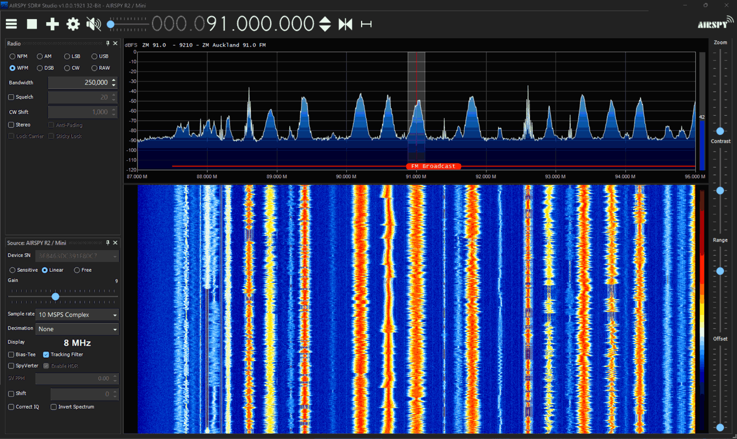
HydraSDR (Left), Airspy (Right). Same SNR on BCFM in SDR#HydraSDR (Left), Airspy (Right). Same SNR on BCFM in SDR++HydraSDR (Left), Airspy (Right). Slightly better SNR for the HydraSDR at 457 MHz.
Real World Comparison SDR++ vs SDR# 1921
HydraSDR recommends using SDR++, whereas Airspy recommends using the Airspy native software SDR#. While HydraSDR currently works on SDR#, we're not sure if this will continue, as SDR# could possibly block the use of clones and spinoffs. So, it seems fair to compare HydraSDR with SDR++ and Airspy with SDR#.
Under normal operation, with moderate strength signals, both programs appear to give nearly identical performance in terms of audio quality and signal SNR.
However, Youssef has pointed out that SDR# (and SDR-Console) has a special mode called HDR (high dynamic range) available for Airspy products. HDR mode works by optimizing the DSP chain specifically for the Airspy hardware whenever decimation is used. With HDR mode on, we can push the gain setting much higher than we would have otherwise without experiencing overload, resulting in a better SNR.
We are currently aware that only SDR# and SDR-Console V3 implement the Airspy HDR mode tweaks, and SDR++ does not.
Comparing performance between two different programs can be a bit tricky because each uses a slightly different FFT algorithm, resulting in different SNR values being calculated. SDR++ consistently calculates a somewhat higher SNR for the same signal.
To illustrate the effect of the Airspy HDR mode, we will use two SDR# instances and disable HDR mode for the HydraSDR, simulating the effect of using it in SDR++, which does not have HDR mode.
HydraSDR with HDR Mode OFF (Left), Airspy (Right) HDR Mode ON
This test showed a rather dramatic +7 dB improvement with HDR mode on. With HDR mode on we were able to increase the gain much further without overload. In the screenshot we increased the gain as far as possible to optimize the SNR on each receiver as much as possible.
For an audio comparison that directly compares Airspy on SDR# vs HydraSDR on SDR++, here is an audio file of the Airspy running SDR# with HDR mode ON, 16x decimation, receiving a weak signal sandwiched between strong signals.
And here is the audio file of SDR++ with 16x decimation receiving the same signal.
Both signals were optimized for the best SNR possible which was just before the SDRs overloaded and displayed intermodulation products. There is a clear difference in audio quality that can be heard, with SDR # emerging as the winner. Note that these HDR improvements may only be seen in a high dynamic range environment (when strong signals are mixed with weak signals) and when decimation is used .
Conclusion
With the Airspy R2 starting to feel a bit dated, the HydraSDR looks to be a great addition to the choice of available SDRs. However, we consider it to be essentially a spinoff of the Airspy with some minor changes made to improve performance and usability. The improved shielding and USB-C port are particularly notable enhancements that we love. Compared against the Airspy, HydraSDR is clearly the better hardware choice.
But if you already have an Airspy R2, there are not enough improvements here to consider the HydraSDR as a next-generation upgrade worth purchasing. That said, if you're looking for a new SDR made in the USA, the HydraSDR should be on your radar.
The Airspy maintains some software advantages, such as official software support and compatibility with SDR#’s and SDR-Consoles HDR mode, which excels in strong signal environments. However, the HydraSDR is directly compatible with the Airspy and currently functions as one in SDR#, allowing it to benefit from HDR mode as well. But this compatibility relies on SDR# not actively blocking it. It's also important to note that Youssef has mentioned that, in his view, using the HyraSDR in SDR# would be in violation of the SDR# licensing agreement, as would loading the HDR enhancements in SDR-Console V3 with HydraSDR (note that we have not verified the legality of this claim).
We also note that Benjamin wants to emphasize that HydraSDR is not designed for use with SDR#, and only SDR++ and other HydraSDR software should be used with it.
Disclaimer
We have no financial interests in either Airspy or HydraSDR (apart from reselling the YouLoop). The Airspy R2 used in this review was provided to us back in 2015 as a free review unit, and HydraSDR was provided to us recently as a free review unit. Transparency note: Certain parties have claimed that we gave an unfair review to the HydraSDR because they claim that we take referral credit from sales of Airspy units. This is not true. Several years ago, when Airspy was the main recommended upgrade to the RTL-SDR, we briefly trialled a referral program with Airspy, but that program ended many years ago. Any leftover referral links from old blog posts are no longer active. The only Airspy product we sell on our store is the YouLoop antenna, which is unrelated to the SDRs themselves. Some parties have also pointed out that parts of the original review have been removed, and they claim a lack of transparency. In a previous iteration of the review, we mentioned our thoughts and speculation regarding IP law, but removed these sections due to legal threats.
In a previous video released last week, Matt from the TechMinds YouTube channel reviewed the RigExpert FobosSDR. The FobosSDR is an RX-only USB 3.0 device, with a 100 kHz to 6 GHz tuning range, 50 MHz of bandwidth, and 14-bit ADC resolution. It comes in at a price reasonable for its specs, which is US$395 from US resellers and from EU resellers around 495,00 €.
However, while the specs look good on paper, Matt's previous review exposed some severe imaging problems with the device, and noted that lower cost SDRs with similar specs performed much better. Imaging is when strong out of band signals overlap onto other bands, causing issues with receiving signals. This is usually a symptom of incorrect code, poorly thought out design, or poor filtering in hardware.
In the latest video Matt goes through RigExpert's reply to his video review. In the video the reply from RigExpert stresses that only certain sample rates chosen by the user will result in correct performance in terms of imaging. When the correct sampling rate is chosen Matt observes that the imaging is resolved on the HF bands, although it does not help with the broadcast FM band imaging onto the airband in VHF.
RigExpert also stresses that the FobosSDR is not designed to be a high performance HF SDR and that it is designed to excel in the 50 MHz to 6 GHz range only. However, Matt points out that their marketing goes against this statement, as it advertises that FobosSDR has applications in "high performance HF" and "HAM radio".
They also note that the official software for FobosSDR is uSDR, and this should be used for best performance. But in his tests, Matt notes that the uSDR software has poor audio quality and FFT resolution on the waterfall, with no settings found to improve it.
Overall, many of the problems seem to stem from a disconnect between the marketing, documentation, and technical people working on the FobosSDR. It also seems that some of the issues could have been solved with additional or tighter built-in filters. But with the retail cost already in the upper range of this spec bracket, they may have opted for the cheaper option which is to tell users to use external filters if necessary.
Earlier this year the Ukrainian company RigExpert released the FobosSDR, and only recently has it become available to most people in the world via global resellers. FobosSDR is an RX-only USB 3.0 device, with a 100 kHz to 6 GHz tuning range, 50 MHz of bandwidth, and 14-bit ADC resolution. Current pricing from US resellers is US$395 and from EU resellers around 495,00 €.
Recently Matt from the TechMinds YouTube channel reviewed the FobosSDR, showing an unboxing, description and review of the hardware. Unfortunately, while the specs on paper look good, Matt notes that the FobosSDR does not perform well.
In the video, Matt starts by testing around the broadcast FM band and shows how the FobosSDR suffers from multiple mirrored signals, even with the gain settings turned right down. He notes that other similarly priced SDRs perform a lot better and that even an RTL-SDR performs better.
Matt then goes on to test the HF bands, noting that there is no gain control available on these bands and that there are also extreme levels of signal mirroring all across the HF band.
Unfortunately, we are starting to see other similar reports about poor performance from the FobosSDR. For example, on arcticdx's blog he also does not recommend the SDR [1][2],
Last year the RFNM (RF Not Magic) software-defined radio was announced and opened up for pre-orders. RFNM is an SDR based on the new 12-bit LA9310 baseband processor chip, and together with either a 'Granita' or 'Lime' daughter board it is capable of tuning from 10 - 7200 MHz or 5 - 3500 MHz respectively. It is also capable of wide bandwidth - up to 153.6 MHz on a host device like a PC. The RFNM is affordable, costing US$299 for the motherboard, US$179 for the Lime board, and US$249 for the Granita board. Currently, the second production batch is available for preorder.
Recently we received our RFNM order, with both Granita and Lime boards. This is a review of our initial impressions and tests on it. Note that while the RFNM is capable of transmitting, in this review we did not test that capability.
Physical Review
The RFNM motherboard comes as a PCB with a large heatsink on the bottom and a very quiet inline fan. The daughterboards connect to the motherboard with a board-to-board connector and are secured in place via seven screws. There is another board-to-board connector for a second daughterboard to be connected, but in this review we did not test it.
On the right side there is a 4-18V DC barrel power jack and USB-A, USB-C, HDMI and Ethernet connectors. There is also a SIM card and SD card slot on the side. On the left of the board are MMCX connectors for external reference clock, and clock out. There are also various header pinouts for PPS OUT/IN, UART, I2C, GPIO and PWM. On the heatsink side there is a JTAG connector, jumpers for resetting the firmware, and pads to solder on an OCXO.
RFNM Motherboard and DaughterboardsRFNM bottom with heatsink, fan and rubber feet.
The device feels solid but there are a few exposed SMT components on the rear that have the potential to be knocked off with rough handling. All the main connectors are through-hole soldered and will not break off easily. During operation, the heatsink stays warm to the touch, and does not get too hot. The fan blades are exposed but should be safe from fingers and debris being on the bottom.
Initial Firmware Download
The device requires power from a 4 - 18V DC barrel jack and connects to a PC via a USB-C or USB-A port. According to the developer, it requires a 10-15W capable supply. In the tests below we used a 9V 2000mA switch mode supply, and a 12V 3000mA capable linear supply.
The device comes shipped without firmware, and the first setup step involves plugging in an internet-connected ethernet cable to automatically download and install the latest firmware. If you don't have an internet connected ethernet cable, an alternative is to plug in a USB stick with the latest firmware installed on it. The firmware installation took only a couple of minutes and went smoothly.
Initial Tests with SDR++
The easiest way to get something working with the RFNM is to use the custom SDR++ build included on the RFNM itself. When you plug in the RFNM it shows up on your PC as a disk drive, with an SDR++ folder. Getting started is as easy as running that SDR++ exe and clicking Play.
Initially, we encountered an issue where the RFNM wouldn't show up in SDR++, and wouldn't show up as a disk either. However, after flipping the USB-C connector it worked. This is an issue that continued throughout, and sometimes flipping wouldn't even work, but it always connected after a few reconnection attempts, and once the board was connected it was stable.
Lime Daughterboard Tests
We first tested the RFNM with the Lime daughter board. This is a board based on the Lime LMS7002 chip which is the same chip used in the LimeSDR. Here only the IQ output of the Lime chip is used, not the ADCs.
At this point, it's important to note that software support for the RFNM is still in the very early stages and SDR++ currently has no gain controls implemented. SDR++ is third-party software to RFNM so it's not any fault of the RFNM team. (NOTE: In the last few days after having already written this review, there have been several commits to SDR++ regarding RFNM, so this may already be resolved)
However, it is possible to SSH into the Linux OS system running on the RFNM system and change the gain setting through a bash command. To connect to SSH a network-connected ethernet cable needs to be connected to the board (alternatively you can use the UART port on the side of the board with an adapter). Once logged in via SSH we can browse to "/sys/kernel/rfnm_primary/rx0" and edit the value in the 'gain' text file. Then to activate the changes, simply set the value in the 'apply' text file to 1. This allowed us to optimize the gain settings for best reception.
cd /sys/kernel/rfnm_primary/rx0
echo 30 > gain && echo 1 > apply
RFNM with Lime daughterboard on the WiFi bandsRFNM with Lime daughterboard receiving mobile basestation signals.
With the ability to set the gain, the Lime board works great. Signals are strong in the VHF and UHF bands where sensitivity is approximately -135 dBm, and there is little sign of imaging with appropriate gain settings. In the 2.4 GHz band, the sensitivity remains good at around -130 dBm too. Although the advertised max frequency range is 3500 MHz, we were able to receive up to about 3.85 GHz with reduced sensitivity.
On HF, however, the Lime board performs very poorly. We start to see a drop off at around 50 MHz where the sensitivity is roughly -93 dBm, at 30 MHz about -58 dBm, and 15 MHz about -37 dBm.
Granita Daughterboard Tests
In the second test, we removed the Lime board from the RFNM motherboard and installed the Granita daughterboard. The Granita daughterboard is based on an Arctic Semiconductor 'Granita' chip, an RFFC2071A mixer, and several preselectors.
Unfortunately, we are very disappointed in the performance of Granita as there is very significant imaging of signals, and this wipes out the ability to cleanly receive almost every band. According to Davide, this problem is a firmware issue with the Arctic Semiconductor Granita chip that can maybe be fixed in the future, but there is no guarantee that it is fixable, as any fix is at the mercy of the Arctic Semiconductor, who don't seem to be very responsive to the issue. Davide (creator of the RFNM) writes:
In the Lime board, the IQ LPF works properly. For granita, it doesn’t work at all, like the -3 dB point of the 20 MHz LPF option is 100 MHz+. The manufacturer of the RFIC kept saying that this is a firmware bug, so I gave them a devkit to replicate, but they never fixed it over the last month. I don’t know at this point if this is a software problem or if they discovered it’s something more.
We confirmed that adjusting the gain settings on Granita did not help with the imaging problem either.
Heavy imaging was experienced with Granita (compare this to the true WiFi spectrum shown previously with the Lime board).
We also noticed that Granita was picking up or internally generating significant noise spikes. We initially assumed this was from the 9V SMPS, but even with a 12V linear power supply similar spikes were seen. The same noise was not visible with the Lime board.
Granita unknown noise spikes
Sensitivity in the bands above 600 MHz was good, at around -135 dBm. Below 600 MHz where the mixer is used, sensitivity was a bit poorer at around -123 dBm. The highest frequency we could receive was around 5900, but after about 5 GHz signals started to become very weak. The Granita board is advertised as receiving 10 - 6300 MHz, however, the documentation notes that the current batch is only capable of tuning to around 5 GHz. They note that the next batch should reach 6.3 GHz.
The Granita board was able to receive broadcast AM, shortwave, and ham frequencies with good signal strength. At 15 - 50 MHz the sensitivity is roughly -115 dBm.
Granita receiving the 0 - 15 MHz.
At the time of this review, we cannot recommend that anyone purchase the Granita board unless they are working in a very controlled environment. We hope that in the near future the IQ LPF problem can be fixed to make the Granita board usable.
GNU Radio Tests (Windows)
The file drive on the RFNM also comes with a Soapy driver available. We copied the RFNMSupport.dll file from the RFNM drive over to our GNU Radio radioconda installation's SoapySDR folder at C:\Users\proje\radioconda\Library\lib\SoapySDR\modules0.8. Then we opened GNU Radio and opened the gnuradio_example.grc file. This brings up a FFT and waterfall display like in SDR++ and with the Gain controls exposed. With the gain controls exposed the Lime + RFNM combination works great.
The daughterboards also have built-in antennas that can be switched in or out using a drop down box in the GNU Radio UI. The built-in antenna on both boards is a Pulse W3796 which has an advertised range of 698 MHz to 2.7 GHz. While the built-in antenna works well for nearby bench reception, we preferred to still use our outdoor dipole antenna for better reception.
153.6 MHz Bandwidth Mode
It's possible to set the RFNM to provide even more bandwidth by connecting two USB cables to the PC. That gives us up to 153.6 MHz of 12-bit data. Enabling this mode requires editing a variable via the terminal
Once this was set we were able to edit the samp_rate block in the GNU Radio example, and set it to 153.6 MHz. At the moment the current SDR++ does not support the 153.6 MHz sample rate.
RFNM Running 153.6MHz in GNU Radio.
Conclusion
It's clear that the RFNM is cutting edge, yet affordable, and has great potential and excellent features and specifications. The built-in processor, DSP and GPU capabilities on the RFNM could be game changers in the near future. However, at the time of this review, the software support is still in its very early stages, documentation is lacking, and it's not yet recommended for mainstream users who just want to plug in and get started with an SDR for listening and decoding signals.
Regarding the Granita daughterboard, we would probably hold off on purchasing this until there is some clarification on the IQ LPF fix.
If you are an advanced SDR user who is comfortable with GNU Radio, Linux and advanced applications like setting up and running mobile basestations, then the RFNM may be a good choice. We are looking forward to applications that make use of the onboard DSP and GPU capabilities.
The Raspad 3.0 is a portable tablet enclosure for the Raspberry Pi 4B. It comes with a high resolution 1280 x 800 10.1 inch touch LCD screen, built in speakers, built in battery and a plastic enclosure that houses the LCD driver board and Raspberry Pi. Accessible on the side of the enclosure are the USB, HDMI, ethernet and audio ports which connect via the LCD driver board. They also include an accelerometer shim which allows the screen to autorotate.
A few months ago SunFounder, the company behind the RasPad 3.0 reached out to us and asked if we wanted to review the product with a free sample. Normally we don't review products unrelated to SDR like this, but given the amount of RTL-SDR software available for the Raspberry Pi, and what appeared to be sufficient internal space, we were curious if there was a way to turn this into a portable RTL-SDR tablet...
The RasPad 3.0
Unboxing
A few weeks ago the Raspad 3.0 arrived, well packed and with all the advertised components. Note that the Raspad 3.0 does not come with a Raspberry Pi 4B, this is something you will need to provide on your own.
Inside was a mains power cable, 15V DC power brick, two HDMI jumpers, a USB jumper, accelerometer shim, SD card ribbon, small 5V fan, heatsinks for the Pi, screwdriver and mounting screws, a manual and the RasPad LCD screen itself.
The Raspad 3.0 Box and Unboxing
Assembly
Assembly is straight forward. You unscrew the enclosure using the provided screw driver, insert the Pi 4B, screw it down, connect all the cables from the Pi to the LCD driver board and SD card slot, then reassemble. After inserting the Raspberry Pi 4B and attaching all the cables this is what the inside looks like.
Inside an assembled RasPad 3.0
Now we could have reassembled the enclosure here, but we wanted this to be a portable RTL-SDR tablet, with the RTL-SDR and an SMA antenna port built in.
It turns out that the best way to fit in an RTL-SDR Blog V3 is to directly connect it to the spare USB port on the Pi. You might also consider using a micro style RTL-SDR which would fit more easily, but those do tend to get quite hot in a small package, and can be quite bad with internal noise. Also good shielding is probably quite critical in this application due to the dongles proximity with the LCD driver board which could be an RFI source.
The SMA side of the RTL-SDR Blog V3 rests nicely on top of the USB port of the LCD driver board providing some stability, and when the bottom lid is assembled there is plenty of clearance and no squashing.
Next we drilled a hole on the rear wall of the bottom half of the enclosure for the SMA female port, and tightened the SMA connector down with a nut. In the future we'll be upgrading this to a long barrel style SMA female connector, as a regular SMA female connector is a bit short. Then a short well shielded SS405 coax cable was used to connect to the RTL-SDR dongle.
RasPad 3.0 with RTL-SDR Blog V3 InsideRaspad 3.0 with SMA port hacked in
ProTip: Do take care to remember to remove the SD card when disassembling the RasPad! If you don't you'll end up with the SDcard slot getting ripped from it's ground traces. This happened to us, but we were able to easily solder it back on. There is a sticker on the backside of the enclosure warning about this.
Software & Testing
SunFounder provide a custom Raspbian distribution designed specially for the RasPad. However, we decided to instead install the DragonOS Pi64 Distro which is an Ubuntu distribution for the Raspberry Pi 4B that has many built in SDR programs. We burnt the image to a SD card, inserted it on the side, plugged the Raspad in to the power connector, and held the power button down for a few seconds to turn it on. Despite a few initial error messages saying it cannot enable the USB ports, everything eventually booted just fine.
We then plugged in a cable going to one of our multipurpose dipole antennas mounted just outside the office window, and tested both SDR++ and GQRX. In both cases we were immediately able to connect to the RTL-SDR and receive signals with signal strength equivalent to that received by our desktop PC, indicating that LCD interference was not a problem.
The resolution of the screen is high enough and images and text are clear. The screen is also decently bright, and brightness can be adjusted using the buttons on the side.
RasPad 3.0 with built in RTL-SDR running SDR++ and GQRX
DragonOS Tablet Compatibility Issues & Fixes
As DragonOS is not designed for a tablet setup, there were a few bugs. It should be noted however that these issues are not a reflection on the Raspad hardware, as obviously the official Raspad OS will not have these issues as it's designed specifically for tablet use.
We initially had no sound in SDR++ from the built in speakers. After some troubleshooting we managed to get sound by disabling the headphone jack in the audio mixer settings, which appears to be the default output in DragonOS. To do this, click on the speaker icon on the bottom right task bar and click on Mixer. Then go to the Configuration tab and uncheck the second Built-in Audio entry. Close it, and open SDR++.
Disabling the headphone jack to get the built in speakers working.
In DragonOS the touch screen works fine, although it is difficult to click on small buttons. There is no onscreen keyboard available by default. We couldn't find a way to enable a tablet mode in DragonOS, so instead opted to install an onscreen keyboard called 'onboard' via 'sudo apt install onboard'. The accelerometer is also not enabled in DragonOS. We did not attempt to fix this as we have no need for screen rotation.
Interference
LCD screens are well known to be sources of RF interference, and putting an SDR in close proximity to one could result in the spectrum being very noisy. However, without an antenna connected we did not notice any interference across the spectrum from the LCD screen. It appears that the LCD RFI noise levels are not too bad, and the shielding on the RTL-SDR Blog V3 and the coax jumper cable is good enough to prevent any being received. When an antenna with a few meters of coax was connected (such as a magwhip or our portable dipole) we also didn't notice any LCD interference.
However, when a SMA telescopic antenna was connected directly to the SMA port we did start noticing the telltale spikes across the spectrum that are typically generated from LCD screens. If the magwhip or dipole was also moved within 2-3cm of the LCD screen, we also saw these interference spikes appear.
LCD Screen interference appears with a telescopic whip connected directly to the SMA port.
So it would be recommended to use a magwhip or dipole that has a coax run that can sit a few centimeters away from the screen. This limits the handheld ability of the RasPad a little, but you'd probably want a magwhip, dipole or other antenna over a directly connected telescopic whip for better reception anyway.
Battery Life
We tested a worst case scenario, with the RasPad running the RTL-SDR and SDR++ continuously at the brightest screen setting. With this test the battery lasted 2 hours and 10 minutes from a full charge. Presumably if the screen was dimmed and turned off for some periods of time, it would easily last 3-4 hours.
Portability
The total weight of the Raspad including our mods is just under 1 kg (2.2 lbs). About double the weight of a modern tablet, but still light enough to be easily carried.
Other Notes
The small 5V fan provided in the kit is unfortunately a bit noisy, and it's cooling ability is seems limited. We've seen these small fans on other Raspberry Pi cooling accessories and found that they are next to useless at cooling. It would be good to see a slightly larger and quieter fan, or perhaps a better passive cooling heatsink.
The power brick output is 15V, 2A. Ideally we would be able to charge the RasPad via a car/boat 12V connection as well. We're awaiting a response to see if this is possible. Update: Unfortunately 12V seems to be a no-go, quoting SunFounder "the 12v supply may cause the Raspad to fail to charge, as the minimum is 15v".
Conclusion
The RasPad 3.0 in our opinion overall a good product. It allows you to easily go portable with your Raspberry Pi 4. While it was designed for other projects, there was just enough hackability left in it for us to fit a RTL-SDR Blog V3 and antenna port into the enclosure, yielding us a clean and portable SDR solution.
With at least 2 hours of battery life when running an RTL-SDR and software, we can easily see this being taken out in the field for spectrum analysis, decoding with rtl_433, or for portable listening to the airband, trunking etc. However, some customization of DragonOS or the RaspadOS is going to be needed to get the most out of the touchscreen.
There are also alternative LCD screen products designed for the Raspberry Pi where you sit the Raspberry Pi on the back of the screen. But it's unclear if there would be enough space inside to fit an RTL-SDR, and not to mention the lack of a battery. We also previously reviewed the Elecrow CrowPi which is somewhat similar, but a lot more clunky if you're just after a pick up and go portable SDR tablet solution. There are also higher end higher priced laptop style enclosure products for the Pi, like the Pi-Top but we're unsure if they're likely to fit the RTL-SDR internally this easily.
Disclaimer: We do not receive any compensation for this review apart from a free Raspad 3.0.
We also recently came across this review from German YouTuber Manuel Lausmann who installed and ran SDR++ on the Raspad with an SDRplay RSP SDR.
The Airspy team have recently been working on a preselector retrofit product for their HF+. The Airspy HF+ already has excellent dynamic range and sensitivity, but by adding a preselector they seek to improve performance enough to claim that the HF+ is as good as or even better than much more pricey SDRs like the Perseus by achieving dynamic range figures of more than 105 dBm.
A preselector is a filter or bank of filters that attenuates out of band signals. This is useful as radios can desensitize if an unwanted signal comes in too strongly. For example, if you are tuned to the 20m band, but there is a very strong MW signal, the SNR of your desired 20m band signal might be reduced. Radios with a natural high dynamic range design like the Airspy HF+ are less affected by this problem, but for the strongest of signals use of a preselector can still help.
The Airspy HF+ preselector needs to be soldered directly onto the HF+'s PCB, and once installed it automatically switches bands using GPIO expansion ports controlled automatically via tuning in SDR#, so no external switching is required.
The expected pricing of the HF+ preselector is US$49, and it will be ready for sale in a few weeks.
Measurements
We received a prototype of the filter a few days ago and have been testing it out. From measurements on a VNA, we found that the preselector features four bands of operation:
0 - 5.2 MHz
5.2 - 10 MHz
10 - 17 MHz
17 - 30 MHz
Airspy have also provided us with a block diagram schematic which we show below.
HF+ Preselector Schematic
Insertion loss appears to be mostly below 3 dB with fairly steep skirts especially on the lower side. The top three filters do an excellent job at blocking out the broadcast AM band. Below are some VNA plots that show the filter responses.
Installation
The preselector comes in a small 3.2 x 1.7 cm sized PCB that is fully covered with a metal shielding can. To install it you need to carefully solder it onto the HF+ PCB. This can be a little tricky since the pads are so small, but if you're experienced with soldering it shouldn't be an issue.
First you need to open the HF+ and remove R3 from the HF+ PCB, which is a zero ohm resistor.
The preselector PCB can then be positioned and the two IN and OUT pads soldered in place.
Then you'll also need to connect the power and 2x GPIO lines to the preselector using wires.
Now you need to bridge the two shielding CANs with a thick bit of wire. We simply used two cuts of copper solder braid to do this.
Finally is also recommended to update the HF+ firmware to the latest version and download the latest version of SDR#.
Once soldered in place the preselector is ready to use, and the HF+ cover can be put back on. It is expected that the commercially sold versions of the preselector will come with detailed installation instructions.
In the first photo below we removed the shield to see what was inside, and the second photo shows it installed on the HF+ PCB.
Using it on a RTL-SDR V3
Whilst the preselector is designed for the Airspy HF+, there's no reason why it couldn't also be retrofitted onto other SDRs, such as our RTL-SDR V3, for use in improving direct sampling mode performance.
The V3 has spare GPIO ports that can be used to control the filter, and 5V for powering the filter could be tapped off the PCB as well. Currently we're considering making a breakout PCB for the filter than might aide with this.
We did a quick test with the preselector connected to the RTL-SDR V3 running in direct sampling mode, and as expected performance is much better, especially above 5 MHz once the second filter kicks in. This is because the second, third and fourth filters all heavily attenuate the MW broadcast AM band, which is the main source of overload issues on HF.
The following screenshots show how much the filter was able to reduce the signal strength of AM broadcast when the second 5.2 - 10 MHz filter was turned on. This reduction was enough to prevent overload on all the higher bands.
HF+ Results
For the HF+ we tested by injecting a strong signal into two HF+ SDRs, one with the filter installed and the other without. The HF+ with the filter was routinely able to withstand much higher signal powers without any signs of overload occurring, and no degradation due to insertion loss was observed.
The screenshots below show an experiment with a weak desired signal injected at 14.2 MHz, and a strong unwanted signal being injected at 1.5 MHz. With the unwanted signal at 5 dBm, the filtered HF+ showed no signs of overload, whilst the unfiltered HF+ had the AGC kick in to increase the front end attenuation, reducing the signal strength by about 20 dB and raising the noise floor.
Other Reviews
Other reviewers have also received the preselector and have been testing it. Fenu radio has uploaded a short review, and plans to write more in the future. He's also made his HF+ with preselector available for public use via SpyServer (details in his post). In the video below Leif SM5BSZ reviews the preselector and runs through several tests while comparing it against the Perseus. His results seem to show that the Persues gets a +25 dBm IP3, whilst the HF+ with the latest firmware and preselector is able to obtain a respectable +10 dBm IP3.
hfpluspresel2
Conclusion
For most people, the dynamic range of the HF+ is probably already more than enough, but if you are receiving very strong signals, the preselector can help get you get more performance out of the HF+. Of course the preselector cannot help if you have strong signals within the filter bands.
If you're looking to get the most out of your HF+ then the filter at only $49 is a pretty good deal. Just take note that you'll need to open the HF+ and be comfortable with soldering onto the PCB.