Receiving GOES LRIT Full Disk Images of the Earth and EMWIN Weather Data with an Airspy
Over on Reddit user devnulling has made a post showing how he was able to use his Airspy SDR to download full disk satellite images of the earth from the GOES satellite. In a separate imgur post he also shows that he was able to receive EMWIN weather data images from the same GOES satellite.
The Geostationary Operational Environmental Satellite (GOES) is a weather satellite placed in geosynchronous orbit (same position in the sky all the time) which is used for weather forecasting, severe storm tracking and meteorology research. It transmits full disk images of the earth on its Low Rate Information Transmission (LRIT) signal, and weather data images and text on its Emergency Managers Weather Information Network (EMWIN) signal. EMWIN is a service for emergency managers that provides weather forecasts, warnings, graphics and other information in real time.
In his post devnulling writes about receiving GOES:
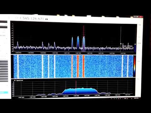
GOES LRIT runs at 1691.0 MHz , EMWIN is at 1692.7 MHz and is broadcasted from GOES-13 and GOES-15. GOES-14 is currently in a backup position to take over in either fails.
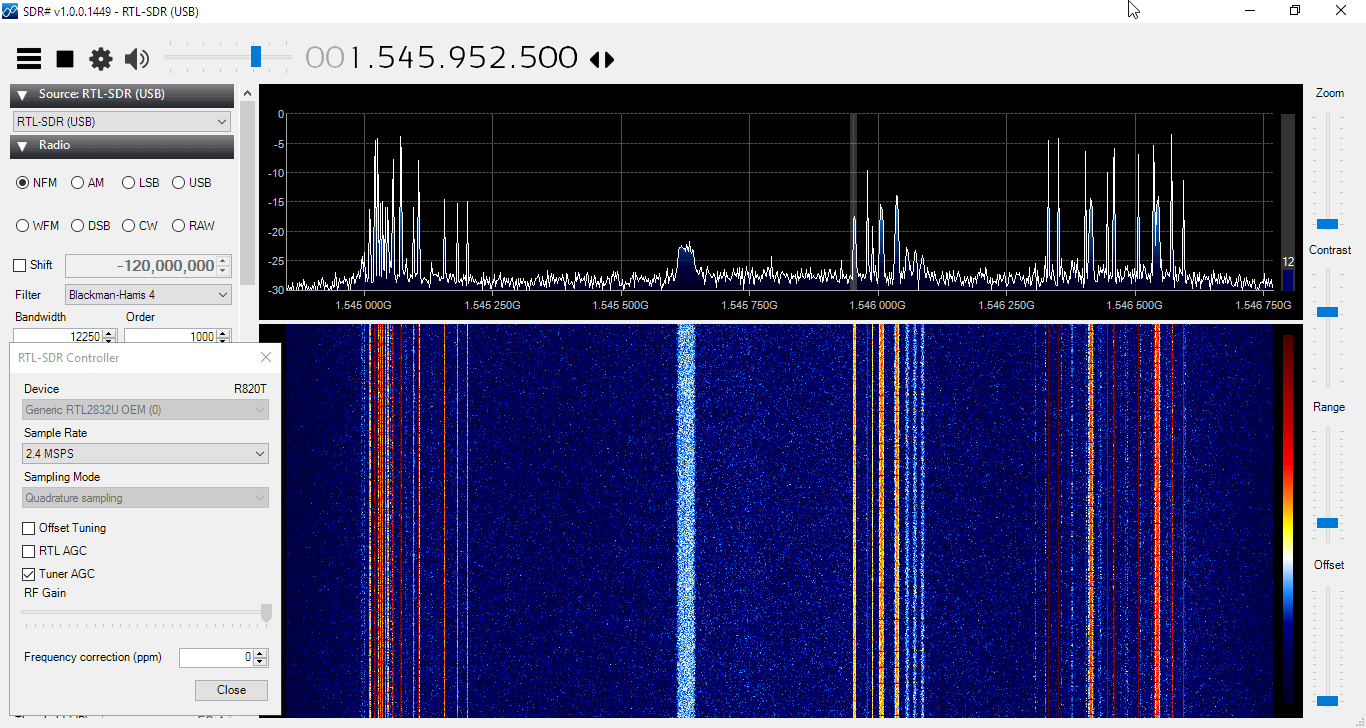
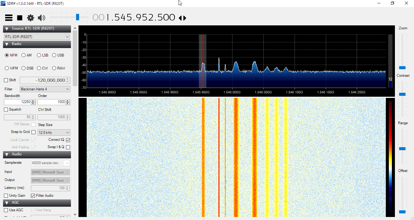
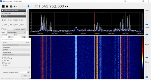
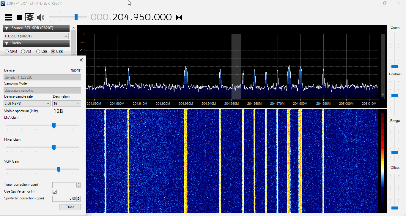
FFT/Waterfall of LRIT + EMWIN – http://i.imgur.com/rgSIORv.jpg
http://www.n2yo.com/?s=36411|29155|35491For the hardware side, it is recommended to use roughly a 1.2m or larger dish, depending upon how far north you are, you may need a 1.8m dish (larger the better). Repurposed FTA or C-band dishes are easy to come by and work well.
I made a 5 turn helical feed with some 12ga copper wire and a piece of copper plate, and used this calculator to design it – https://jcoppens.com/ant/helix/calc.en.php
Picture of my dish/feed setup: http://i.imgur.com/Q1ZBFrs.jpg
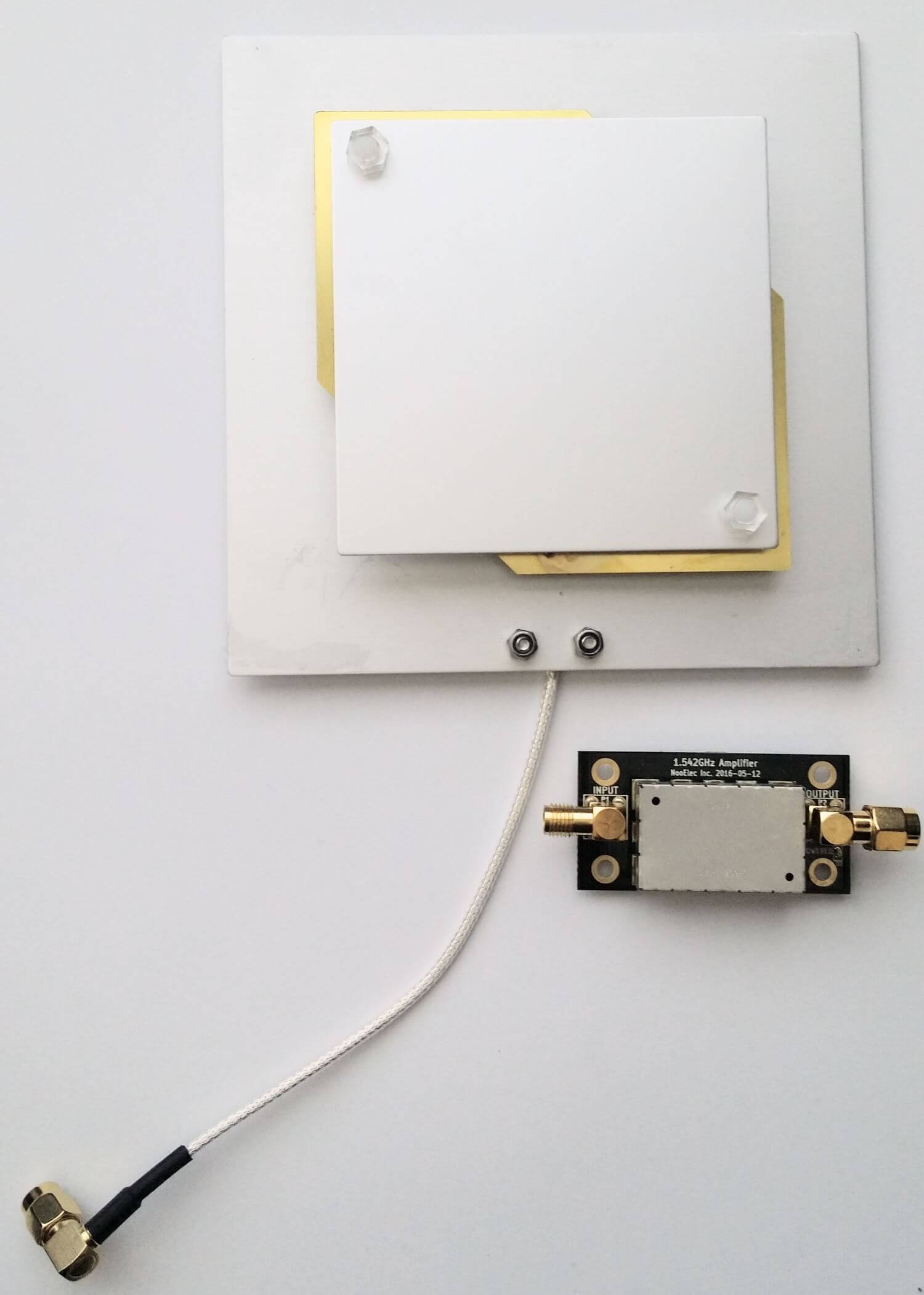
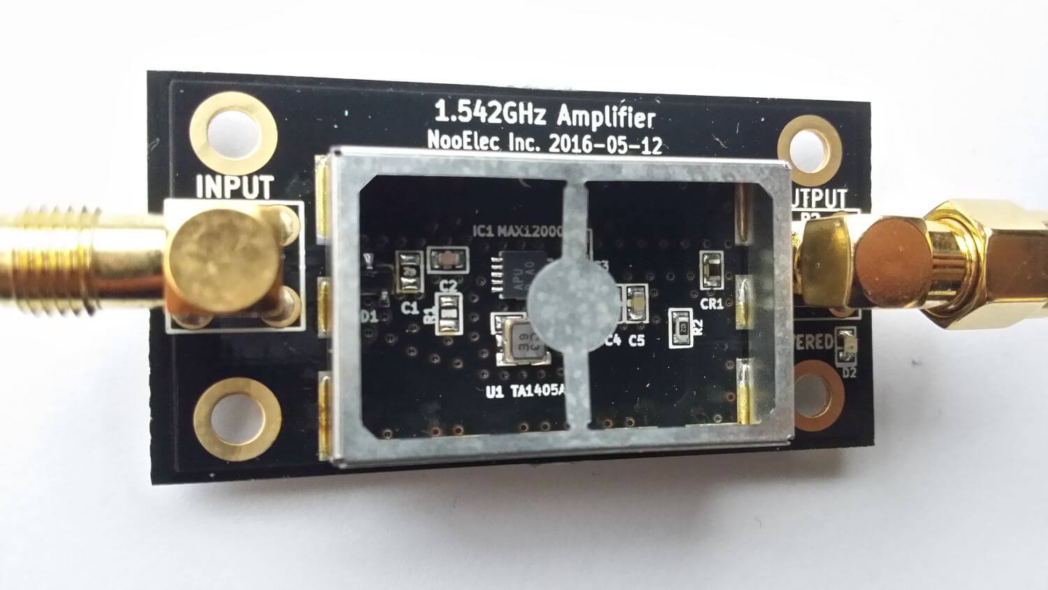
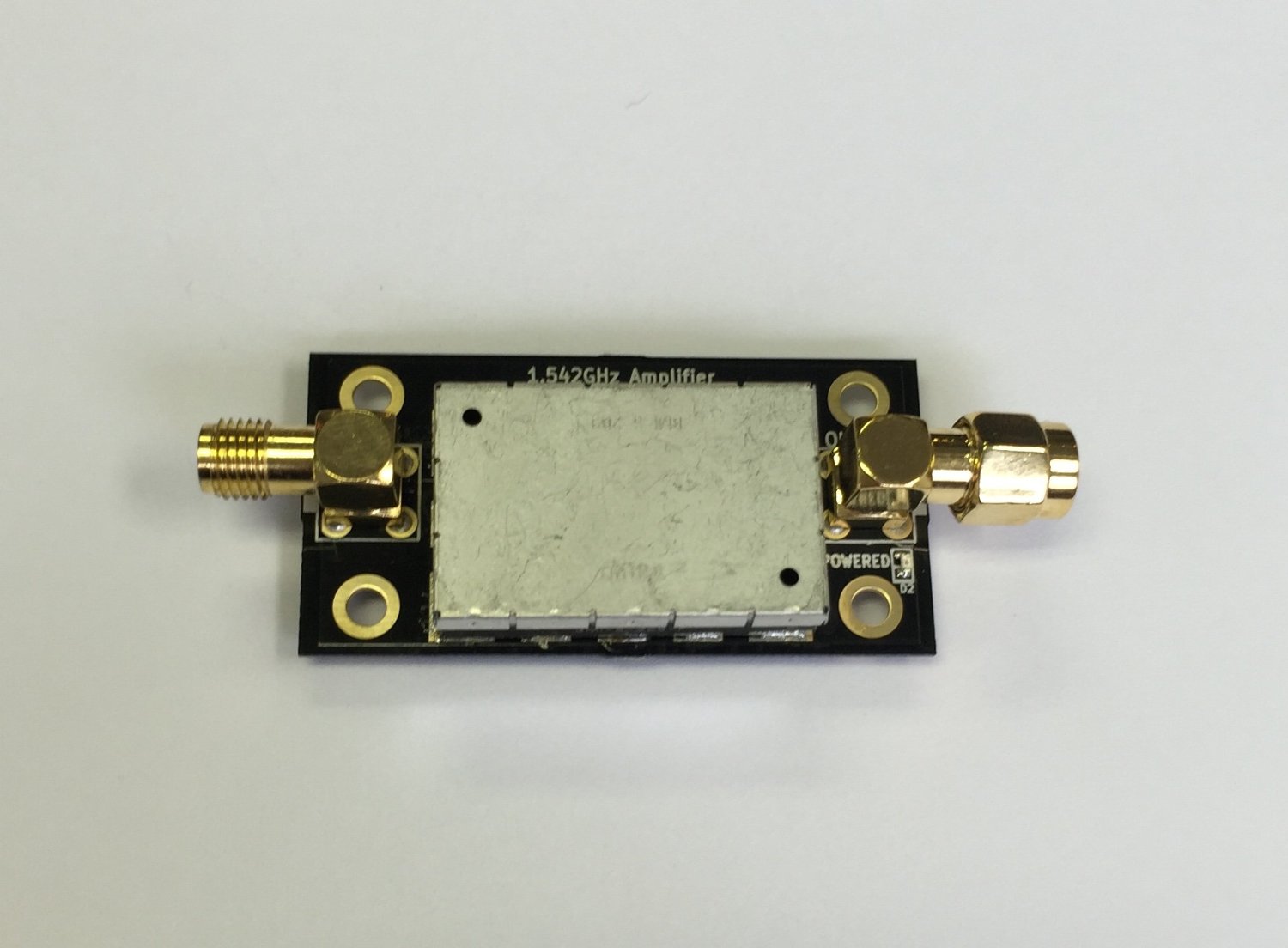
I have a short run of coax into the LNA/Filter box. The first LNA is a TriQuint TQP3M9037 which has a very low noise figure (0.3 dB NF and 22 dB gain at 1.7 GHz).
That is ran into a Lorch 1675 MHz filter (150 MHz pass band), then a LNA4ALL and another Lorch before going over a 30ft run of RG-6 to the SDR.
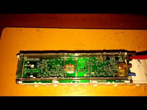
Picture of the LNA/Filter box – http://i.imgur.com/yt7SvFL.jpg
I am using @usa_satcom (twitter.com/usa_satcom, usa-satcom.com)’s LRIT Decoder and that feeds into XRIT2PIC to produce the images and other data streams. By default the decoder only works with the Airspy, but with a custom GNU Radio UDP block, it can be fed with other SDRs like the BladeRF/USRP/SDR Play. A regular R820T(2) RTL probably won’t work because of the higher frequency (rtls tend to not work above 1.5 GHz) and 8 bit ADC. I’m going to try and use the Outernet e4k to see if I can pickup the EMWIN signal in the near future.
EMWIN is broadcasted on 1692.7 MHz, along with being encoded in the LRIT stream at 1691 MHz. The 1692.7 MHz signal is stronger and narrower, so it is easier to pickup. For decoding EMWIN I used @usa_satcom’s EMWIN decoder that piped data into WxEmwin/MessageClient/Weather Message Server from http://weathermessage.com.
LRIT will contain the full disk images from GOES-15, and relayed images from GOES-13 and Himawari-8. It will also included zoomed in pictures of the USA, and northern/southern hemispheres. The images will be visible light, water vapor and infrared. The full disk images are transmitted every 3 hours, with the other images more often. EMWIN will contain other weather data, text, charts, and reports.
Full disk GOES-15 – http://i.imgur.com/tWlmNMW.jpg
Charts / images from EMWIN – http://imgur.com/a/tsn1K
Text data – http://pastebin.com/raw/ULJmSSTP
Zoomed in west coast USA LRIT – http://i.imgur.com/rzfB0SV.jpg
Northern Hemisphere LRIT – http://i.imgur.com/5tKtPmn.jpg
Himawari-8 LRIT – http://i.imgur.com/sVzikys.jpg
Himawari-8 LRIT – http://i.imgur.com/LBvpTD1.jpg
It seems as though it may be possible to receive LRIT and EMWIN signals with an RTL-SDR since the signals are at 1690 MHz, which should be covered by cooled R820T2 and E4000 dongles. The only hardware requirements would be a 1m+ dish, 1690 MHz L-band feed, and an LNA + filter.
In 2017 these satellites are due to be replaced by new ones that will use a HRIT signal, which will be about 1 MHz. New software to decode this signal will be required then, but we assume the same hardware could still be used as the frequency is not due to change significantly.
Please note that the decoding software is only available by directly contacting usa-satcom, and devnulling writes that you must have the proper equipment and be able to show that you can receive the signal first before attempting to contact him.