Every month SDR evangelist Balint Seeber hosts the Cyberspectrum Meetup in San Francisco, where many SDR fans come together to listen to various presentations. This months meetup is live right now (at the time of this post)and you can watch it live now on YouTube, or delayed later now over, but the recorded stream is available for viewing on YouTube. If you are in San Francisco you can attend the live meetup, but if not you can watch the live stream on YouTube.
This time the talks include:
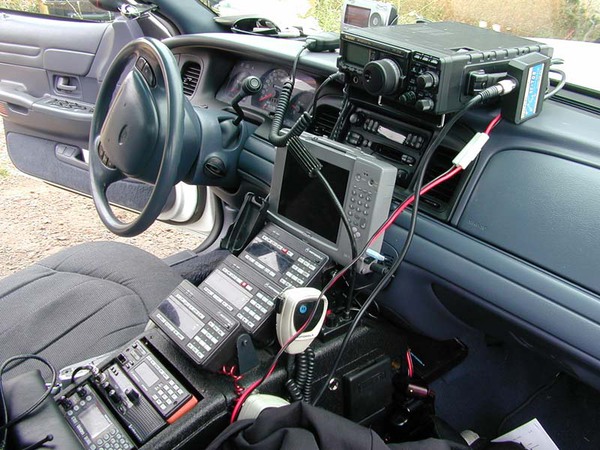
•”The Land Mobile Radio Spectrum: What is out there, how it works, and how you can hear it” with Desmond Crisis (@dcrisis)
Wireless two-way is the technology that keeps the world working in sync. I’ll explore the various public safety, private enterprise, and personal communications services from[masked] MHz. We’ll discuss the occupied spectrum, modulation bandwidths, trunked radio schemes and digital transmission modes currently in use on the band as well as what lies ahead. Bring your SDR kit and play along!
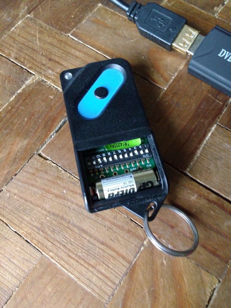
After listening to dock workers with his RTL-SDR for a few days, RTL-SDR.com reader Eoin decided that he wanted to try a more practical experiment. He decided to see if he could reverse engineering the wireless protocol on his garage door opener. Upon opening his remote he discovered a bunch of DIP switches, which are presumably used to program the remote to a particular garage door. Eoin’s next step was to determine at what frequency the garage door opener was transmitting at. He made an assumption that it would be in the 433 MHz unlicenced ISM band as this is where many handheld remotes transmit at. He was right, and found the signal.
The garage door remote showing the DIP switches.
His next step was then to record the signal audio in Audacity. From the audio waveform he could see a square wave which looked just like binary bits. By manually eyballing the waveform and translating the high/low squarewave into bits he was able to get the binary data. He then confirmed this data with the dipswitch positions and discovered that a 010 binary code matched with the UP position on the dip switch and 011 matched with the DOWN position.
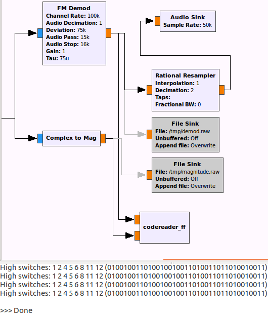
Having decoded the signal manually fairly easily, Eoin decided his next challenge would be to automate the whole decoding in GNU Radio. In the end he was successful and managed to create a program that automatically determines the position of the DIP switches from the signal. His post goes into detail about his algorithm and GNU Radio program.
Showing the decoded DIP switch positions from his GNU Radio program.
Decimation of the sample rate for improved noise performance
Improved performance
Better function support for developers
Callbacks used for stream data and gain updates
Tuner AGC function moved to the API
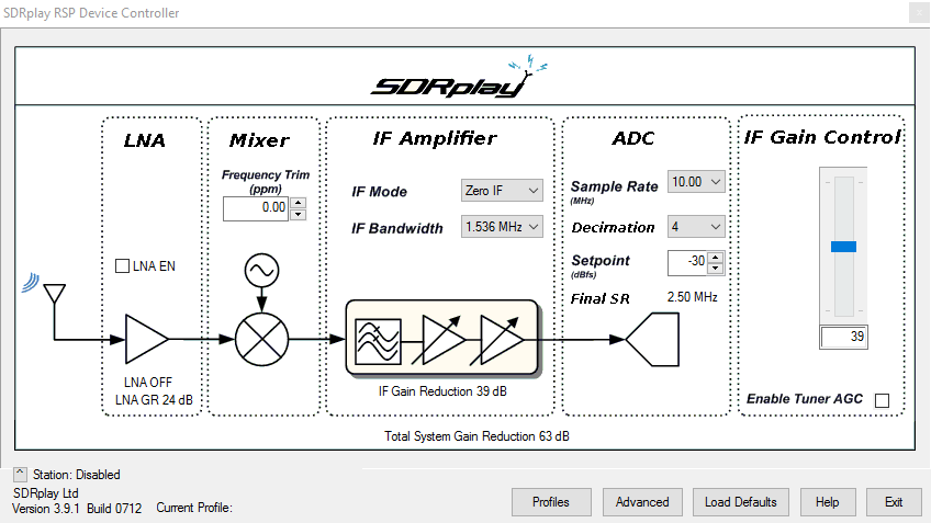
The major changes for users appears to be the the 10 MHz sampling rate and the addition of decimation. The 10 MHz sample rate increases the visible spectrum, however it appears that the maximum IF Bandwidth is still only 8 MHz, meaning that the outer edges of the spectrum won’t show any signals. However,. but the IF filter roll off is not super sharp, meaning that the full 10 MHz should still be usable, with only minor attenuation at the edges. However, we note that in our testing we noticed some roll off at the edges, giving us about 9 MHz of usable spectrum. There should also be an improvement in SNR by using the higher sampling rate thanks to decimation.
Edit: Jon Hudson from SDRplay wrote in to let us know that our assumption of the outer edges being useless was incorrect (the crossed out text). He writes:
I noted one error in what you wrote there…..you suggest that the 10 MHz of visible B-W is worthless because the IF bandwidth is only 8 MHz max and hence you can’t see any signals beyond that 8 MHz window. This isn’t true. The IF filters start to roll off at 8 MHz, but they are not brick wall filters. The actual roll off is at +/- 5 MHz (10 MHz of bandwidth) so within that 10 MHz, at the edges, there are only a few dB of attenuation, and because the CNR has been defined by the front end circuits ahead of the IF filter, any filter attenuation will be applied equally to the signal and the noise leaving the Carrier to Noise ratio unaffected. As a consequence, whilst the user may seem some roll off, the ability to see and receive signals that may lie at the outer edges of the 10 MHz bandwidth is unaffected.
In this update they also added visual decimation controls. This is useful as this allows you to zoom into a signal without loosing resolution whilst maintaining a high sample rate. The decimation controls only appear to activate in the lower IF Bandwidth settings.
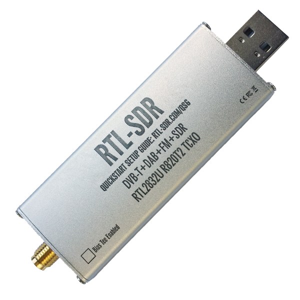
The SDRplay RSP is a $149 USD software defined radio with 10 kHz to 2 GHz tuning range, 12 bit ADC and up to 8 MHz of visible bandwidth.
The new RSP EXTIO control panel showing decimation and 10 MHz sample rate.
As many of you know we have been working on releasing a new revision of our RTL-SDR Blog SDR units for the last few months. We are a few weeks away from being able to release news about this new unit and begin sales. At the moment we are still confirming the features and testing the prototypes so cannot release any news, but if you want a hint at what features might be coming you can take a look at our previous poll asking RTL-SDR users what they wanted in a low cost SDR. The new units may include some of these features/improvements.
For now we are selling off our current batch at reduced prices. The dongle only package is reduced from $19.95 to $17.95, and while the dongle + antenna kit is sold out in our international store, we have reduced its price from $24.95 down to $23.95 on our Amazon USA store.
These prices will only last until this batch of stock runs out, and there are only a few hundred units remaining. This special offer also combines with our 5% off deal if you buy more than two items from our store.
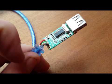
Active USB cables allow cable lengths to be stretched to much longer than the maximum length of 5m allowed by the USB specification. However, although the packet timing requirements are met by the repeaters used in the active cables, there is still a significant voltage drop which can affect devices like the RTL-SDR.
Over on YouTube Shaun Dobbie discovered that his RTL-SDR would not run properly on his long active USB cable, and he suspected low voltage. After opening the case on the USB cable head he discovered two pins which allowed for external power input. By simply connecting an external 5V supply from a battery to the 5V input of the active cable he was able to fix the low voltage problem. If you’ve ever found that a long active USB cable doesn’t work then this may be the problem you have experienced. An alternative to this home solution might be to use an external powered USB hub, or buy an active USB cable that already has an external power input like thisor this one.
Back in April we posted about Philip Hahn and Paul Breed’s experiments to use an RTL-SDR for GPS logging on their high powered small rockets. As GPS is owned by the US military, a standard GPS module cannot be used on a rocket like this, as they are designed to fail if the GPS device breaches the COCOM limit, which is when it calculates that it is moving faster than 1,900 kmph/1,200 mph and/or higher than 18,000 m/59,000 ft. The idea is that this makes it harder for GPS to be used in non-USA or home made intercontinental missiles. As SDR GPS decoders are usually programmed in open source software, there is no need for the programmers to add in these artificial limits.
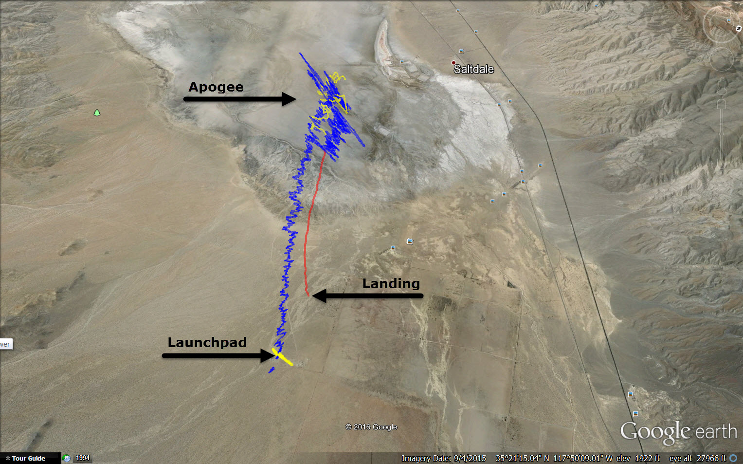
In their last tests they managed to gather lots of GPS data with an RTL-SDR, but were only able to decode a small amount of it with the GNSS-SDR software. In this post Philip discoversa flaw in the way the GNSS-SDR performs acquisition and retrackingthat GNSS-SDR decodes in such a way that makes it difficult to obtain a location solution with noisy high-acceleration data. By using a different GPS implementation coded in MATLAB, he was able to get decoded GPS data from almost the entire ascent up until the parachutes deploy. Once the parachutes deploy the GPS has a tough time keeping a lock as it sways around. His post clearly explains the differences in the way the code is implemented in GNSS-SDR and in the MATLAB solution and shows why the GNSS-SDR implementation may not be suitable for high powered rockets.
In addition, they write that while the flight was just under the artificial COCOM GPS fail limits for speed and height, the commercial GPS solution they also had on board failed to collect data for most of the flight too. With the raw GPS data from the RTL-SDR + some smart processing of it, they were able to decode GPS data where the commercial solution failed.
GPS data acquired from the RTL-SDR on the rocket (blue line shows solution from MATLAB code, yellow shows GNSS-SDR solution, and red shows commercial GPS receiver solution).
To celebrate the fourth of July, the US distributor of Airspy is throwing a sale. The prices are the lowest we’ve ever seen for any Airspy product before. Currently the sale price for an Airspy R2 is $149 (vs $199), $99 for Airspy Mini (vs $114) and $39 for the Spyverter. Unfortunately the sale only appears to be occurring with the USA distributor, and is not available for international customers.
If you’re interested in these products see our previous review on the Airspy R2 vs HackRF vs SDRplay, review of the Airspy Mini, and our review of the SpyVerter. In short the consensus from our reviews is that the Airspy is an excellent product. The Spyverter is also the best upconverter we’ve tried, and is an excellent choice for an upconverter for any other non Airspy SDR, such as an RTL-SDR. And at this price it is even cheaper than most of the alternative options like the ham-it-up.
Over the past few years the Electrical Engineering department of the University of California, Berkley has been using RTL-SDR’s in their EE123 Digital Signal Processing (DSP) course. We’d posted about this course years before when it first came out, but recently Micheal Lustig (KK6MRI), the Associate Professor of the course wrote in to let us know that the course has evolved and is now better than ever.
The course covers DSP essential material such as the Discrete Fourier Transform, Fast Fourier Transform, RF Filter design, as well as more complex subjects. All the course material is available in note and video form if you scroll down on the main page at https://inst.eecs.berkeley.edu/~ee123/sp16/index.html.
However, the professor writes that the best gem that they have developed in their labs which can be found at https://inst.eecs.berkeley.edu/~ee123/sp16/labs.html. The labs run on the web based Ipython/Jupyter Notebooks and guide you through the implementation of an ADS-B receiver, broadcast FM and subcarrier demodulation, frequency calibration with GSM, and a full python APRS transceiver using the baofeng radio and a custom audio interface. These labs are an excellent tutorial into the world of DSP.
The final project of the class is also very interesting. The students of the class were given the task to send images using a Baofeng UV-5R handheld radio and receive them with an RTL-SDR. On the day of the project demonstration they were given two images, and the challenge was to transmit the best quality image over 75 seconds. Videos of the presentation can be found at https://inst.eecs.berkeley.edu/~ee123/sp16/projectVideos.html. The winning team used a combination of five Baofeng’s for simultaneous transmission of a compressed image and an RTL-SDR for receiving.