Running the Airspy ADSB decoder at full speed on a Raspberry Pi 2

Bob W9RAN recently wrote in to let us know about some developments he and Youssef have had with getting the Airspy to function at full speed on a Raspberry Pi 2 with ADS-B decoding. Bob and Youssef created the SpyVerter upconverter, and Youssef is the programmer of SDR# and the co-creator of the Airspy SDR. Bob writes the following:

Airspy is a high-performance SDR that streams 12 bit samples at 20 MSPS (real, not IQ) to a PC where the real processing is done. But 20 million samples per second uses a significant fraction of the bandwidth available with USB 2.0, and has made apparent the weaknesses in USB subsytems on a number of PCs. So of course the natural assumption by “experts” has been that the Raspberry Pi 2 isn’t up to the task.

As we Pi fans know, the Pi 2 has a 900 Mhz 4-core ARM Cortex A7 CPU, and the key to performance is properly implemented code that can take full advantage of the processor architecture.

Youssef Touil, author of SDR# and creator of Airspy has done that, proving first that an optimized multithreaded version of his ADSB decoder would run on a 4-core Odroid that has more CPU power than the Pi 2. But today we have proven that not only can the Raspberry Pi 2 run the optimized ADSB decoder at full speed (20 million samples per second via USB), but that it even has enough horsepower left to run the Virtual Radar Server Google map display in the Pi’s Epiphany web browser!

For those not familiar, the map display is created by a program called Virtual Radar Server that runs on a PC and receives samples from the Pi over ethernet, and includes a web server that allows other computers (in my case, the Pi 2) to view the composite map display. (For more information about ADSB, see my article in QST for January 2014).

I’m really thrilled to be able to demonstrate that the Pi 2 has this
impressive capability! This makes it feasible to create inexpensive high performance ADSB receiving systems, and who knows what else?

Decoding End Of Train and Head Of Train Packets with an RTL-SDR

Back in March 2014 we showed a video of a RTL-SDR user decoding End Of Train (EOT) and Head of Train (HOT) signals. Head of Train (HOT) and End of Train (EOT) signals are used on trains to transmit telemetry data such as brake line pressure and monitor accidental separation of the train. If you live near a trainyard of railway line you may be able to pick up these signals.

Now over on YouTube user berwin018 shows us another video of EOT and HOT signals being decoded. There doesn’t seem to be much information in these packets, but they could potentially be used to track which trains are passing by.

To decode EOT and HOT packets you can use the softEOT software which can be downloaded from the softEOT Yahoo! Group after requesting and being accepted into membership.

Decoding End Of Train & Head Of Train Packets

DSD+ Updated to Version 1.101

DSD+ (Digital Speech Decoder+) is a popular decoding tool that can be used to listen to P25, DMR and other unencrypted digital speech signals. Recently DSD+ has been updated from version 1.074 to version 1.101.

The new version brings several changes, including the ability to decode Hytera Extended Pseudo Trunk (XPT) systems, Airspy compatibility, performance improvements and a TCP/IP link from FMP to DSD+ (no longer need to use a virtual audio cable). The full change log is as follows:

DSD+: Fixed AMBE tone frame audio generation.

FMA: Added Airspy-compatible FMP (FMPA.exe)

DSD+: Significant reduction in CPU usage when monitoring busy control channels. Improvement will be most noticeable on low power processors.

DSD+: Detection and decoding of Hytera Extended Pseudo Trunk (XPT) systems.

DSD+: The DSD+ -i command line parameter can contain an IPV4 address; this lets DSD+ connect to a copy of FMP that is running on a different PC in your local network or on the Internet

Example: DSDPlus -i192.168.1.150:20001

DSD+: NEXEDGE radio alias editing

DSD+ now marks auto-generated NEXEDGE radio aliases in the DSDPlus.radios file by prepending an asterisk like so:

NEXEDGE, … yyyy/mm/dd hh:mm, *”aliastext”

If you edit a NEXEDGE alias, you must remove the asterisk; this tells DSD+ that the new alias text is NOT auto-generated and DSD+ will not replace it with OTA alias text

FMP: FMP command line processing

The FMP command line format has been modified and is now similar to the DSD+ command line. A summary is listed here:

FMP rev 1.4t

Usage:
FMP [options] Normal operation
FMP -h Show help

Options:
-i<num> RTL SDR device number (1-255) [-i1]
-o<num> Output audio device (1-255) [-o1]
-o<port> Output audio TCP port (256-65535)
-P<num> PPM value (-999.9-999.9) [-P0.0]
-g<num> RF gain (dB) [max]
-f<MHz> Initial tuned frequency [-f99.9]
-b<kHz> Initial filter bandwidth (4, 7, 9.5, 12.5) [-b7]
-z<num> Show zoomed spectrum (0-1) [-z1]
-e<num> Enable/disable economy mode (0-1) [-e1]
-n<num> Select noise filter (0-2) [-n0]
-v<num> Set volume level (0-500) [-v100]
-s<num> Enable/disable scanner mode (0-1) [-s0]
-wsl<v>.<h> Spectrum window location [-wsl50.50]
-_<num> Minimize windows at startup; bitmapped
-rv Role is trunk voice channel monitor

-rv puts FMP into voice following mode (same as pressing ‘V’ in FMP)

Any shortcuts or batch files that run FMP will have to be modified to match the new command line format.

DSD+: Less processor loading (probably only noticeable on very slow processors)

DSD+: Much faster groups/radios files loading/saving

DSD+: Editing existing radio aliases

In previous versions of DSD+, editing of pre-existing radio aliases can not be done with an external text editor while DSD+ is running; only radio records with no alias text can be edited

With DSD+ 1.092, existing radio alias text can be edited in an
external text editor while DSD+ is running; DSD+ will load and display any updated radio aliases

DSD+: A DSDPlus.radios file corruption bug has been fixed

DSD+: A command line option to add system details to event log entries has been added

-E Add NAC/RAN/DCC/RAS data to event log file entries

DSD+: Decoding of more DMR and TIII messages has been added

DSD+: A symbol recovery bug has been fixed

DSD+: Con+ handling has been modified; previous versions of DSD+ would create “DMR” entries in the DSDPlus.groups and DSDPlus.radios files for traffic on monitored voice channels; DSD+ 1.090 creates “Con+” entries; if you have “DMR” entries with nonzero NID fields, you should either bulk delete them or change their protocol string from “DMR” to “Con+”; Notepad has a simple search/replace function that can be used to do this

DSD+: A command line option to minimize windows at startup has been added

-_<num> Minimize selected windows at startup (bitmapped, 0-15) [-_0]

value window

1 console
2 source audio
4 channel activity
8 event log

sum values to minimize multiple windows

DSD+: Several high contrast display modes have been added

-H<num> High contrast mode (bitmapped, 0-63) [-H0]

two bits are used per graphical window; pressing ‘H’ in a window will cycle it to the next display mode; pressing ‘W’ displays the current -H<num> value in the event log window

DSD+: Control of AMBE and IMBE unvoiced audio levels has been added

-UA<num> AMBE unvoiced speech level (0-100) [-UA50]
-UI<num> IMBE unvoiced speech level (0-100) [-UI50]

pressing ‘A’/’a’/’I’/’i’ will also adjust the levels;
lower levels may reduce the “underwater” sound of some comms

DSD+: DSD+ can get its raw audio source from FMP via a TCP link instead of via Virtual Audio Cable or VB-Cable

-i<TCPport> FMP TCP link port number (256-65535)

linking FMP to DSD+ via VAC or VBC is deprecated; please use the TCP
link feature instead; any port number between 10000 and 65000 should be fine

DSD+: DSD+ can record separate .wav files for each voice call

-P<wav|mp3> Also create per-call wav or mp3 files

the file names encode metadata:

time
duration
protocol
NID
site number
NAC/RAN/DCC/slot
call type (group/private)
target
source

note: per-call mp3 files are not supported at this time

FMP: A command line option to minimize windows at startup has been added

-_<num> Minimize selected windows at startup (bitmapped, 0-3) [-_0]

value window

1 console
2 spectrum display
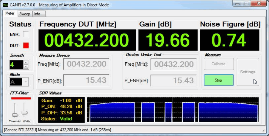
CANFI: Cheap Automatic Noise Figure Indicator Updated to V2.7

Back in July 2014 we posted about the CANFI (Cheap Automatic Noise Figure Indicator) system. The CANFI system is a set of hardware components that include an RTL-SDR and a corresponding software program for control. Back then the CANFI system only supported E4000 dongles. However, recently CANFI was updated to version 2.7 and now supports the R820T/2 tuners as well. The documentation has also been heavily improved. The authors of CANFI introduce their system as follows:

One of the main tasks for an experimenting microwave amateur is to measure the Gain (G) and Noise Figure (NF) of a particular receiving device. For this one will need a Noise Figure Indicator and a (calibrated) Noise Source.

There are a number of commercial devices available from different vendors at prices which will exceed an amateur’s budget by many times. A lot of them can be found on the surplus market but this doesn’t help very much. A combination of both meter and noise source is barely sold below the 2.000€ margin.

Since a lot of cheap DVB – T sticks became available the idea was born to use it together with a homebrew noise source as a very cheap alternative to commercial devices [1]. It is now possible to build a suitable solution within a budget of 100 – 200€. Using a PC with USB port for communication and power supply such a device is very compact and almost compatible to an industrial solution. Special software gives a convenient user interface. Last not least you can reuse the DVB-T stick (together with the preamplifier) as a sensitive receiver along with SDR software.

To create a CANFI system you will need an RTL-SDR, a MGZ 30889 preamp, a noise source, a 28V boost converter to power the noise source and a serial to USB converter to control the noise source.

The CANFI GUI
The CANFI GUI

RTLSDR-Airband V2 Released

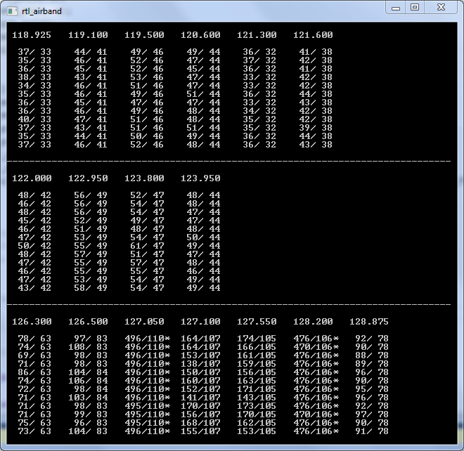
Back in June of 2014 we posted about the released of a new program called RTLSDR-Airband. RTLSDR-Airband is a Windows and Linux compatible command line tool that allows you to simultaneously monitor multiple AM channels per dongle within the same chunk of bandwidth. It is great for monitoring aircraft voice communications and can be used to feed websites like liveatc.net.

Since our post the development of the software has been taken over by a new developer szpajder, who wrote in to us to let us know that he has now updated RTLSDR-Airband to version 2.0.0. The new versions improves performance and support for small embedded platforms such as the Raspberry Pi 2, but the Windows port is now not actively maintained and probably does not work. The full list of changes is shown below:

  •  New libconfig-style config file format
  • util/convert_cfg: can be used to convert old-style config.txt to the new format
  • Syslog logging (enabled by default)
  • Daemon mode
  • Reworked makefiles, added install rule
  • /dev/vcio is now used to access GPU on Raspberry Pi; creating char_dev no longer necessary
  • Startup scripts for Debian and Gentoo
  • Support for auto gain setting
  • Support for multiple outputs per channel
  • Support for recording streams to local MP3 files
  • Support for ARMv7-based platforms other than RPi (eg. Cubieboard)
  • Updated documentation
  • Numerous bugfixes and stability improvements

Compilation and install instructions can be found on the projects main GitHub page.

RTLSDR-Airband
RTLSDR-Airband

Deocoding Orbcomm with MultiPSK 4.31 and an RTL-SDR

MultiPSK is a signals decoding program with many available decoders to choose from. It is also able to directly connect to the RTL-SDR, or be used via a virtual audio cable. The latest beta version (available on the MultiPSK Yahoo mailing list) now allows for decoding of Orbcomm satellites which transmit at around 137 MHz. While it is not possible to decode the encrypted messages, it is still possible to decode pieces of telemetry data from the satellites. MultiPSK writes the following information about Orbcomm:

This system has been developed by the ORBCOMM society which disposes of a constellation of about 28 active LEO (“Low Earth Orbit”) satellites, transmitting between 137.2 and 137.8 MHz (+/- 2.5 KHz maximum of Doppler shift).

This system permits:

  • to handle messages (encrypted) from ground users
    (ships, trucks, oil wells…) until other ground users, through the ORBCOMM satellites, the cover being worldwide. These frames are decoded by Multipsk but not deciphered.
  • to broadcast identification, frequencies, position and orbital elements pieces of information, not encrypted. These frames are decoded and interpreted by Multipsk.

This mode is available for licencied copies, only (otherwise, the decoding is stopped after 5 minutes).

One user of MultiPSK has uploaded a video showing the Orbcomm decoding in action.

Multipsk 4.31 decoding Orbcomm

Signal Direction Finding with an RTL-SDR, Raspberry Pi and REDHAWK

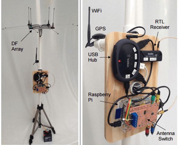
Something we missed posting about from last year was this presentation on “RasHAWK”, a direction finding system (pdf) built out of a Raspberry Pi, an RTL-SDR and four antennas on a 4 way switch running software created with REDHAWK. REDHAWK is a visual DSP development platform that can be considered similar to GNU Radio or some parts of MATLAB. The authors write:

The RasHAWK team has used a Raspberry Pi as the basis for a networked RF sensor capable of supporting spectrum monitoring, signal intercept and direction finding (DF) operations.

Several RasHAWK sensors are deployed in a distributed sensor grid, wirelessly tethered to a command and control (C2) laptop. The system has the following key features and capabilities:

  • A simple operator interface to configure the sensors
  • Falling raster and PSD displays to monitor the spectrum for signal activity
  • Demodulate FM signals from target FRS radios and play audio on selected channels
  • Perform coarse DF on target emitters
  • Display a map of the surrounding terrain that is annotated with the positions of the sensors, the target emitter and calculated lines of bearing (LOB) to the target. The map provides a RF Common Operating Picture (COP) with can be viewed on WiFi enabled tablets or smartphones.

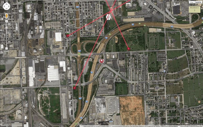
Each RawHAWK sensor can determine the bearing of transmitted signal. By combining several networked RasHAWK sensors at different locations they are able to pinpoint the actual location of the transmitter on a map.

The RasHAWK system.
The RasHAWK system.
Lines of bearings combined from three different RawHAWK sensors.

SDRPlay RSP API Updated to Version 1.8.0

The SDRplay team have recently released a major update to their API and drivers. The new version is 1.8.0 and they write that it should remove the DC offset, reduce in band images from strong signals, and lower the noise floor. The SDRplay is a software defined receiver that costs $149 USD. They write:

We are pleased to announce release 1.8.0 of the API for the RSP. This is a major upgrade to the API with new features and an improved gain map which should result in improved performance over a key portion of the gain control range. Currently this API is available for Windows only, but versions for Linux and Mac OS and Android will follow shortly.

The API now incorporates automatic post tuner DC offset correction and I/Q compensation. This will almost completely eliminate the DC centre spike that was previously present in zero IF mode and also correct for amplitude and phase errors in the I/Q signal paths that can lead to in-band images when strong signals are present.

There is a new gain map for the RSP which should help improve the receiver noise floor for gain reduction settings in the range of 59-78 dB. To achieve this, the IF gain control range has been increased from 59 to 78 dB. In addition, the user can now turn the LNA on or off at any point within the IF gain control range. This means that the LNA can remain on for gain reduction settings of up to 78 dB, whereas previously the maximum gain reduction that could be attained whilst the LNA was on was only 59 dB. Being able to leave the LNA on will result in improvements in the receiver noise performance for gain reductions in the range of 59 to 78 dB. The upper 19 dB of the IF gain control range have now been disabled. In practice this part of the gain control range was useless as trying to operate within this region always lead to receiver overload even when signals were very weak.

To fully exploit the features of this new API release, we have also issued release 3.5 of the ExtIO plugin. This plugin will work with HDSDR, SDR sharp (releases 1361 or earlier) and Studio 1. Automatic I/Q compensation and DC offset correction will work with later versions of SDR sharp, but we will need to update the native plugin for users of these later versions to be access the new gain map.

Similarly, users of SDR Console will gain the benefit of automatic DC offset compensation and I/Q correction, but will not yet be able to access the new gain map. We hope that a version of SDR console that unlocks this feature will become available in the near future.

Until a new release of SDR-Console is available, you can copy the API into the SDR-Console installation directory…

from C:\Program Files\MiricsSDR\API\x64\mir_sdr_api.dll to C:\Program Files\SDR-RADIO-PRO.com\mir_sdr_api.dll

The API installer has also contains an extra certificate to be more user friendly for Windows XP, Vista and Windows 7 users.

The new API and ExtIO plugin can be downloaded from our website at:www.sdrplay.com/windows.html

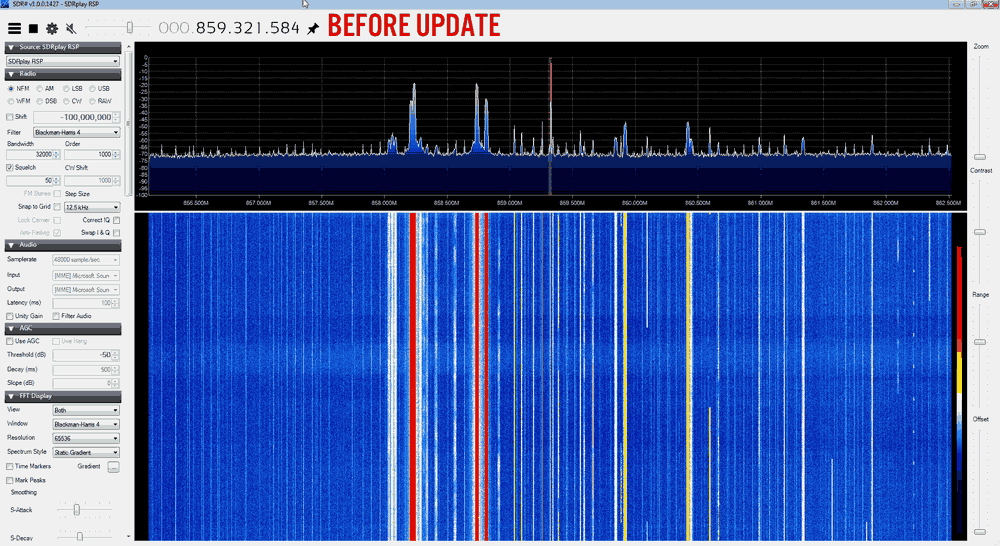
As they write that in band images from strong signals are reduced in this version we decided to do a quick before and after test using our own RSP receiver. We tuned into some TETRA signals that had exhibited images in the past on our RSP (you can see them as the yellow signals in the before image). In the new driver the images are completely gone.