Adam writes that the filter will be most useful for those living in urban areas that are close to radio and TV towers. The filter is built on his standard filter PCB which also has the ability to add a simple bias tee circuit for powering externally positioned LNA’s such as his LNA4ALL which are necessary for good reception at L-band with an RTL-SDR.
He is currently selling it fully assembled for 20 euros, plus 5 euros for worldwide shipping.
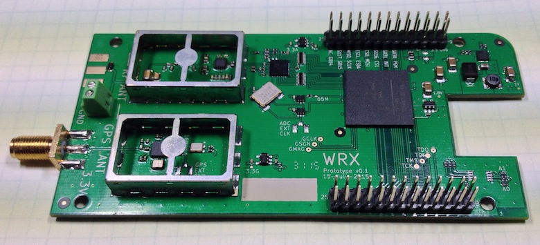
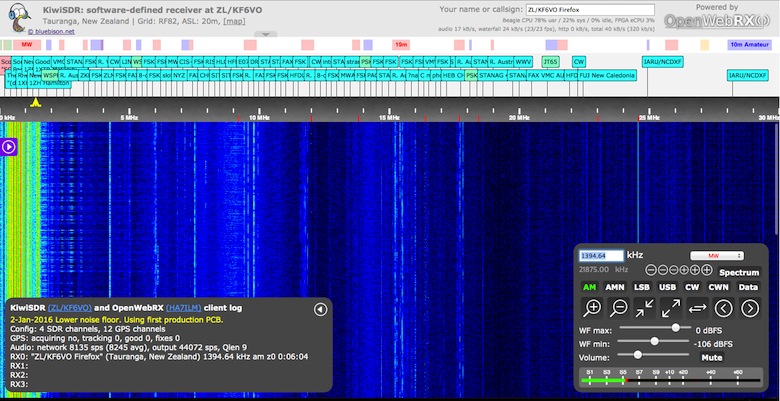
The KiwiSDR is an up and coming VLF/LF/MF/HF capable SDR that has a large 30 MHz of instantaneous bandwidth and coverage from 10 kHz to 30 MHz. It is designed to be low cost and used as an online internet based SDR in a similar way to how WebSDR is used, however KiwiSDR is designed to be used with the OpenWebRX software from András Retzler, HA7ILM. It uses a LTC 14-bit 65 MHz ADC and Xilinx Artix-7 A35 FPGA, and also has an integrated SDR based GPS receiver which is used to automatically compensate for any frequency drift from the main 66.6 MHz oscillator. The features of the KiwiSDR include:
100% Open Source / Open Hardware.
Includes VLF-HF active antenna and associated power injector PCBs.
Browser-based interface allowing multiple simultaneous user web connections (currently 4).
Each connection tunes an independent receiver channel over the entire spectrum.
Waterfall tunes independently of audio and includes zooming and panning.
Multi-channel, parallel DDC design using bit-width optimized CIC filters.
Good performance at VLF/LF since I personally spend time monitoring those frequencies.
Automatic frequency calibration via received GPS timing.
Easy hardware and software setup. Browser-based configuration interface.
The KiwiSDR is currently in beta testing and has released two OpenWebRX beta test sites which can be used at:
A while back we posted about Samy Kamkars popular “RollJam” device, which was a $32 home made device that was able to defeat rolling code based wireless security systems such as those used on modern cars.
Wireless security researcher Andrew Macpherson became interested in RollJam and has now written up a post showing how to create a similar device using the YardStickOne and RFcat wireless tools. In his post Andrew shows how he automates the replay attack side of things using a Python script and two RFcat devices. He also fully explains how rolling codes work and how to attack them using the CodeGrabbing/RollJam technique. Andrew explains the RollJam technique as follows:
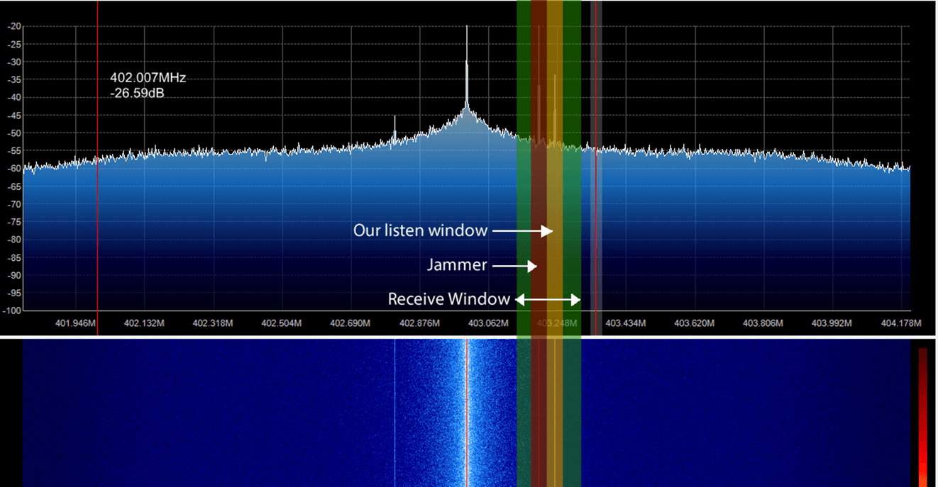
Target parks their car, gets out the carAttacker launches a jammer that prevents the car from receiving the code from the remote
Target presses the remote, car does NOT lock and the attacker obtains the first keypress
Target presses the remote a second time and the attacker obtains the second keypress
Attacker then sends the first key press to lock the car, car locks as per normal
Target assumes all is well and carries on about their day
Attacker then sends the second keypress to the car, unlocking it
Profit.
Target returns to the vehicle and remote works as per normal
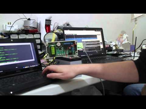
In the video below Andrew uses an SDR to help demonstrate the RollJam attack.
6. jam and replay rolling code rolljam codegrabbing
DSD+ (Digital Speech Decoder+) is a popular Windows tool that can be used together with an RTL-SDR to decode digital speech signals such as P25 and DMR. There is unfortunately no version for OSX.
However, recently on YouTube user Matthew Miller has uploaded a video showing DSD+ running with CubicSDR on OSX. To do this he used a utility called “Wine Skin” which creates a wrapper that allows Windows software to run on a MAC computer running OSX. This means that DSD+ can be run on directly OSX without the need to use a virtual machine with Windows installed on it.
Jupiter and its satellites like Io sometimes interact to create “radio storms” which can be heard from earth at frequencies between 3 to 30 MHz. The radio storms can be predicted and Mario uses the Windows software Radio Jupiter Pro to do this. This helps to predict when are the best times to listen for emissions. On his Raspberry Pi Mario has also written a python script that can do the predictions too.
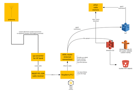
To make the radio emissions measurements, Mario uses an RTL-SDR dongle and upconverter together with rtl_power to gather FFT frequency power results and waterfall plots. To measure the emissions Mario writes that he keeps the frequency scan running for at least several hours a night with a Raspberry Pi as the receiving computer. For his antenna the low Jupiter frequencies necessitate a large 7 meter dipole tuned for receiving at 20.1 MHz.
For the Internet of Things side of the project, Mario envisions that several amateur radio astronomers around the world could run a similar setup, with all sharing the data to an Amazon AWS data storage server. Mario has already written software that will do the scan and automatically upload the results to the server. To participate you just need to write to him to receive the AWS IoT authentication certificate files.
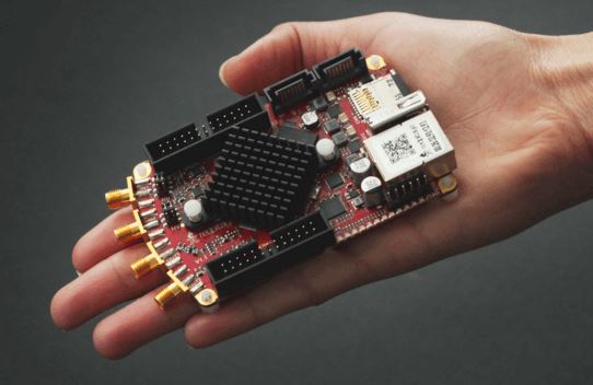
The Red Pitaya is marketed as a type of digital oscilloscope, and is more accurately described as a type of digital measurement and control tool that sells for about $220 USD. However the technology behind its operation (high speed ADCs) is basically the same as what is used in a software defined radio like the RTL-SDR. By using the correct software, and by reconfiguring it’s onboard Xilinx FPGA, the Red Pitya can be turned into an SDR transceiver.
The internet of things is set to become the next big thing in technology. The IoT consists of multiple networked devices such as sensors and computers connected in various ways such as via wireless communication protocols. LoRa is an abbreviation of “Long Range” and is one such wireless protocol that is being used in IoT devices.
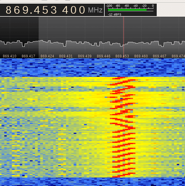
[LoRa] is a radio modulation format that gives longer range than straight FSK modulation. This is achieved by a combination of methods: it uses a spread spectrum technique called Chirp Spread Spectrum (CSS) and it uses forward error coding (in combination with whitening and interleaving).
Over at the RevSpace hackerspace, a hardware hacker called bertrik has been working with his RTL-SDR to try and reverse engineer the LoRa protocol. His goal is to make it so that anyone can receive and decode LoRa signals without needing to purchase specific hardware that supports the modulation. The reverse engineering work is not yet finished, but bertrik has already determined many parts of the protocol by looking at the signals in Audacity. He also writes that there is currently a ready made LoRa decoder available for sdrangelove, a Linux based SDR receiver application similar to GQRX and SDR#.
You might also be interested in this previous article we posted about the Z-Wave wireless networking protocol being hacked with a HackRF.
The two most important things to pay attention to when receiving AERO signals are signal SNR and frequency stability. In order to lock on to the signal, the signal’s frequency must remain relatively stable over a short period of time. For the stability test Jonti writes the following, referencing the image posted below:
You can see the old RTL dongle moves almost 3kHz within a couple minutes after being turned on, this speed is so rapid that JAERO can’t keep up with the frequency changed during this period of time. What’s odd is the old RTL dongle does some fairly crazy stuff around 20 minutes in that lasts for about 15 minutes, JAERO also can’t cope with some of that. The other thing to notice in the old RTL’s spectrograph are vertical lines, these lines I believe are caused by interference entering the dongle between the RTL dongle’s tuner and ADC (analog-to-digital converter).
The frequency stability of the new RTL dongle can only be described as amazing!!! There is not much more than 100 Hz change during the whole test.
The range of frequencies for the SDRPlay is similar to that of the old RTL dongle of about 3kHz. The difference being the transition from the lowest frequency to the highest frequency is slow. Any demodulator should not have any issue tracking this slow and steady change. The only problem you will encounter here is when you are trying to tune into a particular frequency your frequencies will be slightly different depending on the temperature of the SDRPlay.
The results of the frequency stability test on an AERO signal. Left: Standard RTL-SDR; Middle: RTL-SDR Blog Unit; Right: SDRplay.
Jonti also found that in terms of sensitivity the SDRplay was the best at receiving when a non active antenna (an active antenna is an antenna with a built in LNA) was used. The RTL-SDR dongles could not receive well at all when a non active antenna was used. When an active GPS antenna was used the SDRplay was only about 1dB more sensitive than the RTL-SDR dongles.
In his article Jonti expressed concern that the SDRplay did not see much improvement in SNR over the RTL-SDRs when an active antenna was used. Our thoughts on the sensitivity findings are that the SDRplay does not see much improvement with an active antenna because the noise figure of the system is not reduced any further by adding an additional front end LNA (the noise figure in a RF system is almost entirely determined by the first LNA in a RF chain). Adding an extra LNA could even potentially make reception worse by reducing the overall linearity of the system. An external LNA would only be beneficial if a long run of coax was used between the feed and SDR, and in Jonti’s connections he connected the feed and SDRplay with a very short cable. The RTL-SDR only works well with an active antenna because its raw sensitivity at 1.5 GHz isn’t great, and it needs the extra boost from the LNA.