Measuring the return loss of the standard RTL-SDR whip antenna

Most low cost sellers of RTL-SDR dongles bundle them with a cheap fixed length whip antenna. Over on YouTube Adam 9A4QV has measured the return loss of these whip antennas with his vector network analyzer to determine at what frequencies you can expect decent performance. The return loss indicates at what frequencies you can expect a good impedance match, and thus a good standing wave ratio (SWR). The lower the return loss the better the impedance match and thus less power is wasted in the antenna meaning better receive performance.

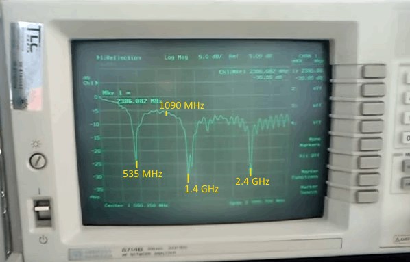
Adams results found that without a ground plane the antenna has a return loss of less than -10dB at around 625 MHz and about 1.40 GHz. With a ground plane (placed on a metal surface) the antenna has good performance at around 535 MHz, 1.4 GHz and 2.4 GHz. This is not surprising as the antenna is designed for DVB-T TV, of which most signals are transmit near 535 MHz. Adam also remarks that the performance at the ADS-B frequency of 1090 MHz with or without ground plane is quite bad.

DVB-T antenna return loss with ground plane
DVB-T dongle whip antenna test

Demonstrating the RTL-SDR based “Etch-A-SDR” Portable SDR

Over on YouTube user devnulling has uploaded a video showing his “Etch-A-SDR” project. This project involved creating an all-in-one SDR device out of an Odroid C1, Teensy 3.1 and an RTL-SDR dongle. The Odroid C1 is an embedded computer, similar to the Raspberry Pi 2 and the Teensy 3.1 is a microcontroller development board. The “Etch-A-SDR” is named as such because of its resemblance to an Etch-A-Sketch toy. It has two knobs that can be used for tuning and several side buttons for changing demodulation modes etc.

Upon boot the Etch-A-SDR opens GQRX and is ready for tuning within seconds of turning it on. In addition to using it as a portable SDR with GQRX the Etch-A-SDR can also be booted into normal Linux mode and into Etch-A-Sketch mode, where it operates as a normal Etch-A-Sketch toy.

The code can be downloaded from https://github.com/devnulling/etch-a-sdr.

The Etch-A-SDR portable SDR

Building and Testing an L-Band Patch antenna for Inmarsat-C Reception

Over on YouTube Adam 9A4QAV (creator of the LNA4ALL and other RTL-SDR related products) has uploaded two videos showing his home made L-band patch antenna in action receiving Inmarsat-C and in the second video describing the construction of the antenna. Inmarsat is a geostationary satellite service that provides services such as satellite phone communications, broadband internet, and short text and data messaging services. Some of the messages on the Inmarsat STD-C NCS EGC channel are marine safety messages that are decodable with an RTL-SDR. This was discussed in our tutorial that we posted back in August. In that tutorial we used a prototype patch antenna that was supplied by Outernet.

Adam’s home made L-band patch antenna consists of two thin sheets of conductive metal, cut to the right dimensions which are described in the second video. We have recorded the dimensions here (though be sure to double check with the video for correctness):

Reflector Size: 170 mm x 170 mm
Patch Size: 98 mm x 98 mm
Corner Trim: 21 mm from top right and bottom left corners
Coax Connection (Probe): 25 mm from bottom edge
Height of patch from reflector: 7 mm

The corners of the patch need to be trimmed to give the patch antenna right hand circular polarization (RHCP), which is the polarization used by Inmarsat Satellites. 

The first video shows the patch in action with Inmarsat-C being received. In this video he also uses a simple downconverter to shift the 1.5 GHz Inmarsat-C frequency down to 300 MHz, which avoids the problem of the RTL-SDR not working very well at 1.5 GHz and above. In the second video Adam explains the dimensions of the antenna.

Inmarsat-C reception - Patch antenna & d/converter conv gain 30db

RHCP L band patch antenna

Building a super cheap dipole antenna for receiving ADS-B with an RTL-SDR

Over on YouTube user Brian Su has uploaded a video showing his super simple dipole antenna that he uses for ADS-B. A dipole is essentially just two pieces of conductive wire, one connected to the centre conductor of the coax, and one connected to the shield. By cutting the dipole to the correct length good reception can be obtained. In the video Brian uses some copper wire for the dipole and also shows the antenna in action with RTL1090 and PlanePlotter.

Building a very cheap and effective 1090Mhz antenna for ADS-B reception

Video showing SMS Texts and Voice Calls being sniffed with an RTL-SDR

Over on YouTube user Osama SH has uploaded a video briefly showing the steps needed to use an RTL-SDR dongle to sniff some SMS text messages and voice calls made from his own phone. This can be done if some encryption data is known about the phone sending the messages, so it cannot be used to listen in on any phone – just ones you have access to. In the video he uses Airprobe and Wireshark to initially sniff the data, and find the information needed to decode the text message. Once through the process he is able to recover the SMS message and some voice audio files.

New Demo of the Upcoming Spyverter Upconverter

The Spyverter is a new high performance upconverter that is being developed by the team behind the Airspy software defined radio and the SDR# software. It is designed to be used together with the Airspy, but it should also be compatible with other SDRs as well. The main claimed advantages over other upconverters will be it’s low loss and high IIP3 performance, which means that the Spyverter will not saturate in the presence of strong signals as easily as other upconverters.

Recently W9RAN, who is involved in the design and testing of the Spyverter uploaded some demo videos of the Spyverter + Airspy combo in action. The first video shows how the Spyverter when used together with the Airspy and SDR# allows for seamless tuning between VLF, HF through to VHF/UHF (no need to set any offsets).

Seamless tuning of SDR# with AIrspy & Spyverter

The next video shows the Spyverter + Airspy combo working during a RTTY contest on 40M with very densely packed signals, some of which were very strong.

W9RAN demo of Spyverter in 40 meter RTTY contest

W9RAN (ranickel on YouTube) also has additional Spyverter + Airspy videos on YouTube for viewing if you are interested.

Reverse Engineering Wireless Mobile Traffic Lights with an RTL-SDR

When roadworks suddenly appeared on Bastian Bloessl’s girlfriends street the workers put up a set of automated wireless traffic lights to control the flow of traffic during the works. Seeing these lights, Bastian quickly grabbed his RTL-SDR dongle and got to work on reverse engineering the status telemetry signals transmitted by these lights.

Wireless traffic lights reverse engineered with an RTL-SDR

Bastian discovered two signals at around 170 MHz which corresponded to two pairs of lights. By analyzing the signal in Baudline and Audacity he discovered that the signal was AFSK1200 modulated between 1200Hz and 2400Hz. He then created a simple GNU Radio program which was able to output the frame bit data. After some analysis he was able to make sense of the structure and create a simple web interface that visualized the data as virtual traffic lights on his PC. The YouTube video below shows the signal and his RTL-SDR decoding software in action.

It seems that the telemetry is unencrypted, however we would assume that the control signals are encrypted.

Traffic Lights + GNU Radio + RTL SDR

Reverse Engineering a Vintage Wireless Keypad with an RTL-SDR

Over on his blog, Veghead has posted about how he was able to reverse engineer a wireless alarm panel keypad from 1986 with an RTL-SDR dongle. The goal of his reverse engineering was to be able to eventually hook it up to a modern alarm system.

By first looking at the old FCC label on the keypad, Veghead discovered that the device transmitted between 319 MHz and 340 MHz. He then used his RTL-SDR dongle to take a recording of the transmitted signals, before opening them up in Audacity – a free audio processing program.

By analyzing the waveform in Audacity, Veghead discovered that the alarm panel uses simple ON-OFF Keying (OOK) modulation. Although the frequency of the signal drifted a lot (probably due to aged components), he was able to write a decoder that he called cletus which converts the recorded complex I/Q signal into a real signal and then uses a state machine to turn the waveform into 1’s and 0’s. Finally the program then outputs the correct button that was pressed to the terminal.

Vintage wireless alarm keypad reverse engineered with an RTL-SDR