Two New SDR# Plugins for Passive Radar and IF Signal Averaging

March 2019 Update: Website appears to be down now. But the DropBox download links are still active.

Passive Radar Plugin: https://www.dropbox.com/sh/tqjycu9nxdfhk0u/AAA9KSE6-mRUwV10s0F9v7Jpa?dl=0

IF Average Plugin: https://www.dropbox.com/sh/tqjycu9nxdfhk0u/AAA9KSE6-mRUwV10s0F9v7Jpa?dl=0

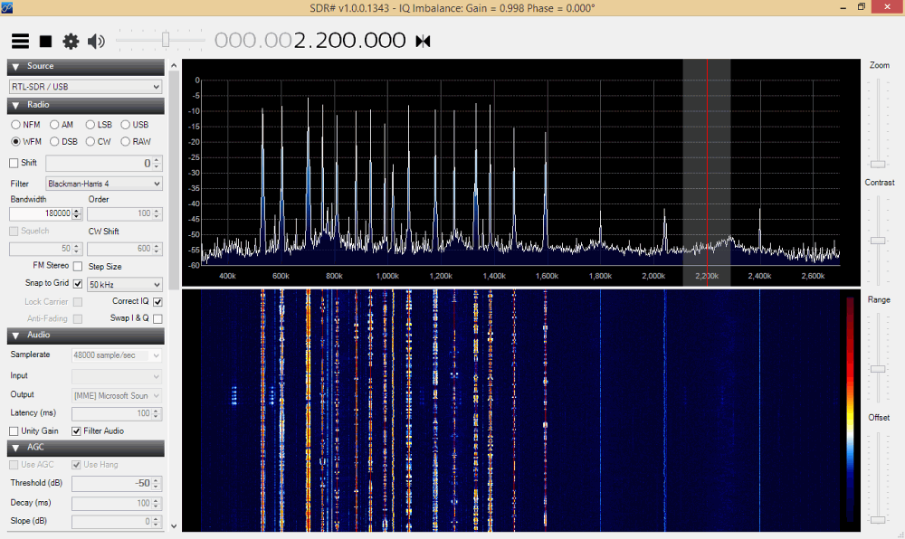
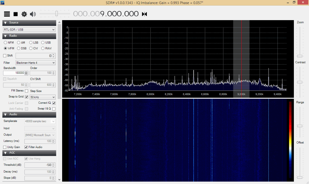
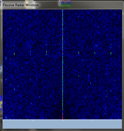
Recently Dr. Daniel Kaminski wrote into RTL-SDR.com to let us know about two very interesting new SDR# plugins that he has developed to use with the RTL-SDR dongle. The first plugin is called "Passive Radar". Passive Radar allows you to use an existing strong transmitter such as an FM station to detect reflections from things like aircraft and meteors. Dr. Kaminski writes about his plugin:

The first one is Passive Radar which bases on the signal from only one dongle. The ambiguity function is the same as in advanced projects with the difference that  I implemented self-correlate function instead of cross-correlate one which is used in 2 dongles projects. Such solution theoretically should works as can be found in internet. It should be noticed that for proper work of such passive radar the direct signal should be comparable in strength to the reflected  one. This plugin is still under development.

In the future he hopes to be able to support two dongle passive radar as well.

The Passive Radar plugin by Dr. Kaminski in SDR#.
The Passive Radar window.

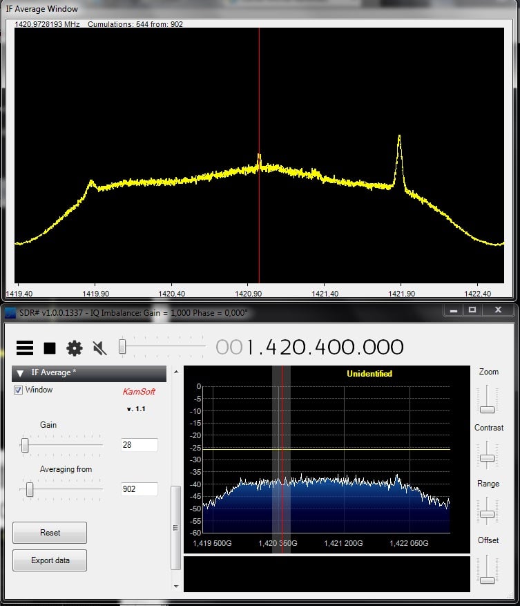
The second plugin is called "IF Average". This plugin allows the IF signal (the entire active bandwidth is what he seems to be referring to) to be averaged which is useful for many applications including radio astronomy projects such as detecting the Hydrogen line. He writes:

The second plugin which is finished is for IF signal averaging. It is important in case of radio-astronomical observations. It allows to cumulate signals (up to 10000 samples in real time), present them in friendly way and save for further work.

The IF Average plugin by Dr. Kaminski.

The plugins require the installation the XNA Framework Redistributable 3.1.

Cooling the RTL-SDR for Improved Sensitivity

Over on his blog, Nobu an RTL-SDR experimenter has made a post about cooling RTL-SDR dongles (post is in Japanese use Google translate if needed). Nobu writes that another RTL-SDR experimenter, Toshi, has previously pointed out that an increase in heat appears to reduce the sensitivity of the RTL-SDR. 

From his measurements, Nobu found that the internal temperature of the RTL-SDR can reach up to 70 degrees Celsius. So in order to cool the RTL-SDR Nobu has tried two methods. One involving using small cooling fans, and the other involving adding heat sinks to all heat producing components. It seems from the translation that he writes that the improved heat dissipation has extended his ADS-B reception slightly.

If you are interested, Nobu also has a previous post where he also mentions cooling of the RTL-SDR.

RTL-SDR Fan Cooling
RTL-SDR Fan Cooling
RTL-SDR Heatsink Cooling

Several PDF Files Related to RTL-SDR’s and HF/MW Reception

Recently RTL-SDR.com reader Dr. Phil wrote in to let us know about some PDF notes that he has created about the RTL-SDR dongle. There is some good information in his documents and the notes mainly focus on using the RTL-SDR with the direct sampling mod to receive HF.

His other documents also explain concepts such as imaging, interference and gain, how to reduce interference, input impedance of the Q sampling pads, intermediate frequency, and sample rate. In addition he has also uploaded some documents where he has calculated for various AM, FM and SW stations at what frequencies images will show up. His final document also discusses the Mirics SDR chipsets which are used in the SDRPlay.

He writes that any corrections are welcome. Dr. Phil’s main website can be found at http://home.comcast.net/~phils_radio_designs/.

Pocket HF SDR: http://home.comcast.net/%7Ephils_radio_designs/Pocket_SDR.pdf

Pocket HF SDR Cookbook: http://home.comcast.net/%7Ephils_radio_designs/SDR_Cookbook.pdf

RTL2832U: http://home.comcast.net/%7Ephils_radio_designs/RTL2832U.pdf

HF Direct Sampling: http://home.comcast.net/%7Ephils_radio_designs/Direct_Sample.pdf

AM Images: http://home.comcast.net/%7Ephils_radio_designs/AM_Images.pdf

FM Images: http://home.comcast.net/%7Ephils_radio_designs/FM_Images.pdf

SW Images: http://home.comcast.net/%7Ephils_radio_designs/SW_Images.pdf

Generic RTL: http://home.comcast.net/%7Ephils_radio_designs/GenericRTL.pdf

Mirics Chipset: http://home.comcast.net/%7Ephils_radio_designs/Mirics.pdf

A photo of the direct sampling mod with a wire antenna.


RTL-SDR Bias Tee Hack

Over on his blog Elias has uploaded a post that shows how he modified his RTL-SDR dongle to provide remote DC power through a bias tee. A bias tee allows you to inject DC voltage into the coax cable to power active antennas, or devices that need to be near the antenna such as LNA’s. The bias tee prevents DC power from entering the RTL-SDR front end (which would fry it) via a blocking capacitor, and also prevents RF energy leaking into the power supply by using a blocking inductor.

In his post he writes how he made a simple hardware hack to the RTL-SDR PCB to enable 3.3V from the USB power supply to be used to power his active GPS antenna. To do this he removes the static protection diode and connects a nearby 3.3V pad to the antenna output through an inductor. The RTL-SDR already has a DC blocking capacitor in place.

He writes that this mod unfortunately requires the static protection diode to be removed, so the RTL-SDR is no longer protected from static discharge. 

Previously in June of last year we posted about a similar bias tee hack by Fabio, where he used the 5V rail to power an inline LNA.

RTL-SDR Bias Tee Hack

Using the RTL-SDR as a Transmitter

Back in July of last year we posted about a video from oh2ftg where he showed how he was able to get his RTL-SDR to act as a crude transmitter by using the RTL-SDR’s leaky oscillator.

Now another RTL-SDR experimenter, Oscar Steila (IK1XPV) has had a similar idea to use the RTL-SDR as a transmitter, and has taken the idea further than OH2FTG did. 

Oscar decided to take a standard RTL-SDR dongle and modify it so that it outputs a signal from the mixer output of the R820T tuner chip. To do this he removes some unneeded components from the PCB, and wires pin 5 of the R820T to the MCX antenna port through a 100pF capacitor. Pin 5 is connected to the mixer output from inside the R820T chip.

TX mod for the RTL-SDR.

After performing the hack the RTL-SDR is able to output a signal anywhere between 500 MHz to 1500 MHz 1.8 GHz to 3 GHz (see why). To control the output frequency you simply need to tune to the frequency you want to transmit at in SDR# (after setting an offset to account for the R820T’s IF offset). This tunes the mixer in the R820T and causes the output frequency to change.

In the future Oscar hopes to take this idea further by creating a specific tuning application for the generator and finding a way to possibly FM modulate the output.

Using SDR# to tune the TX RTL-SDR, and using another instance of SDR# and RTL-SDR to receive the 1GHz signal.
Using SDR# to tune the TX RTL-SDR to 1 GHz, and using another instance of SDR# and another RTL-SDR to receive the transmitted 1 GHz signal.

Update: Oscar has revised the frequency range from 500 – 1500 MHz to 1.8 GHz – 3 GHz. More information about his new tests can be found at http://www.steila.com/SDR/RFgenmod/index.html.

Building a 520 kHz High Pass Filter for the RTL-SDR

Over on YouTube user kugellagers has uploaded a video showing how he designs and builds a 520 kHz high pass filter for his RTL-SDR dongle + upconverter. In the video he explains how to design the filter with the free Elsie software which is an electrical filter design and analysis program. He then shows how he builds and selects the filter inductors and capacitors and how he assembles the components on a PCB. Finally he demonstrates how his 520 kHz high pass filter is useful for filtering out atmospheric noise from lightning strikes.

Previously we posted about kugellagers’s other video in which he demonstrates his FM bandstop filter and 1.8 MHz high pass filter.

520 kHz High Pass Filter Construction

Retesting Nobu’s 14 MHz Low Pass Filter on a Direct Sampling Modified RTL-SDR

Back in May we did a review of Japanese RTL-SDR experimenter Nobu’s products, which were his HF Upconverter, Galvanic Isolator and 14 MHz Low Pass Filter. The low pass filter was designed to be used with a direct sampling modified RTL-SDR receiver, but unfortunately we didn’t have one of those on hand at the time.

Nobu was kind enough to send us one of his direct sampling modified RTL-SDR dongles that he also has on sale on his Japanese Amazon page. This is a nice little unit that has an upgraded 10 ppm oscillator, and an additional MCX port connected to the direct sampling pins of the RTL2832U chip through an impedance transformer. With this unit we were able to give the low pass filter a better test.

The image below shows the AM broadcast band with the filter in place. Mouse over the image to see the effect of removing the low pass filter. (If on mobile click inside the image, and outside the image to toggle the mouse over effect). We can see that there is some insertion loss from the filter, however with the LPF not connected there is severe interference from the broadcast FM band and some AM signals are completely unusable.  

We repeated the same test at 9 MHz. Again, mouse over the image to see the effect of removing the low pass filter. Once more we see that without the LPF there is severe interference from the broadcast FM band, as well as in this case what looks to be a DAB signal.

Similar interference is found all through the 0 – 14 MHz frequencies without the low pass filter in place and most weak signals cannot be listened to without the filter connected. It is clear that without a low pass filter the direct sampling modification is almost useless in the presence of strong interfering signals, such as those from the FM broadcast band. 

Nobu’s products are made in Japan, and at the moment can only be bought from the Japanese Amazon store [Direct Sampling Dongle – $~48 USD] [HF Upconverter – $~56 USD] [Upconverter Case ~$25 USD] [Galvanic Isolator – $23 USD] [Low Pass Filter – $~23 USD].

To purchase from outside of Japan you can use a third party shopping service available at http://agent.jzool.com/, which will buy and ship the product to you from Japan.

RTL-SDR as a Hardware Random Number Generator with rtl_entropy

Over on his blog, Aaron Toponce has posted a tutorial that shows how to use the RTL-SDR app rtl_entropy.  This app uses the RTL-SDR to create random numbers from the atmospheric noise that it receives from the antenna. Aaron writes:

The theory behind the RNG is by taking advantage of atmospheric noise, which is caused by natural occurrences, such as weak galactic radiation from the center of our Milky Way Galaxy to the stronger local and remote lightning strikes. It’s estimated that roughly 40 lightning strikes are hitting the Earth every second, which equates to about 3.5 million strikes per 24 hour period. Interestingly enough, this provides a great deal of entropy for a random number generator.

In the post Aaron also shows how to put the rtl_entropy generated data through some standardized randomness tests, how to visualize the random output and also shows how to use rtl_entropy to generate 80-bit entropy passwords.

Visualizing the random noise output of rtl_entropy.